Page is loading ...

1 2 3 4 5 6
7
8
9
11
10
12
13
14
15
161718192021222324
31
32
33
34
36
37
38
39
40 41
42
43
46
47
48
49 50
51
52
45
44
25
26
27
28
29
30
35
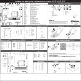
Front Panel Header/ HDD Back Plane Board Header/ 硬盤背板排針
ATX Power/
PMBUS
Installing CPU/ 安装 CPU Memory Populaon Configuraon/ 安装内存
Type
Ranks Per
DIMM and
Data Width
Speed (MT/s);
Slot Per Channel (SPC) and
DIMM Per Channel (DPC)
UDIMM
Unbuffered
DDR4 ECC
UDIMM
Unbuffered
DDR4 non-ECC
SR 1.2V
1.2V
2133 2133
Supported
Voltage
DR 2133 2133
2 Slot Per Channel
1DPC 2DPC
Rear I/O Connector/ 后面板接口
Off
State Description
Yellow On 1Gbps data rate
Green On 100Mbps data rate
10Mbps data rate
SATA Connector/SATA 接口
SATA SGPIO Header/ GPIO
SATA DOM Power Connector
TPM Connector/
COM2 Connector
CPU/System FAN/
USB 3.0 Header
USB 2.0 Header
Front Audio Connector/ 前置音频
S/PDIF In/Out Header Thunderbolt Add-On
Card Header
1 5
No. Pin Define
1 GPIOA
2 GPIOB
3 SLP_S3
4 SLP_S5
5 GND
Case Open Intrusion Header NVidia SLI – System BIOS seng
Open: Normal operaon.
To get best SLI performance, it is recommended
by NVidia to disable VT-d
Please follow below instrucons to disable VT-d
funcon.
1. Press “DEL” to enter BIOS setup menu
2. Select Chipset > VT-d [Enabled] > VT-d
[Disabled]
Closed: Acve chassis intruson alert.
Jumper Sengs/ 跳线设置
1
2
3
4
5
1
4
2 3 3
4 4
6
7
8
912
13
11
10
5
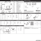
MW31-SP0 Quick Reference Guide/ 快速测试参考指南
1
1
1
1
4
4
5
15
48
1
1
8 2
7 1
7
2423
2
1 2
13 14
1 2
21
109
21
1
1
1
S/PDIF In
S/PDIF Out
1
109
25 26
No. Pin Define
1 3.3V
2 3.3V
3 GND
4 +5V
5 GND
6 +5V
7 GND
8 Power Good
9 5VSB
10 +12V
11 +12V
12 3.3V
No. Pin Define
1 GND
2 GND
3 GND
4 GND
5 +12V
6 +12V
7 +12V
8 +12V No. Pin Define
1 PMBus Clock
2 PMBus Data
3 PMBus Alert
4 GND
5 3.3V Sense
No. Pin Define
1 GND
2 +12V
3 Sense
4 Speed Control
No. Pin Define
1 GND
2 TXP
3 TXN
4 GND
No. Pin Define
1 Clock
2 P_3V3_AUX
3 LPC_RST
4 P3V3
5 LPC_LAD0
6 IRQ_SERIAL
7 LPC_LAD1
8 No Connect
9 LPC_LAD2
10 No Pin
11 LPC_LAD3
12 GND
13 LPC_FRAME_N
14 GND
No. Pin Define
1 MIC2_L
2 GND
3 MC2_R
4 P3V3
5 LINE2_R
6 MIC2_JD
7 F_Audio_Sense
8 No Pin
9 LINE2_L
10 LINE2_JD
No. Pin Define
1 P_5V_AUX
2 SPDIF-IN
3 GND
No. Pin Define
1 SPDIF-OUT
2 GND
No. Pin Define
1 NDCD-
2 NSIN
3 NSOUT
4 NDTR-
5 GND
No. Pin Define
1 5V for SATA DOM
2 GND
3 No Connect
No. Pin Define
1 5V for SATA DOM
2 GND
3 No Connect
No. Pin Define
1 Power (5V)
2 Power (5V)
3 USB DX-
4 USB DY-
5 USB DX+
No. Code Descripon
1 COM1 Serial port
2 HD_AUDIO Audio connectors
3 DP_HDMI Display port port (top) / HDMI port (boom)
4 USB_LAN1 LAN port #1 (top) / USB 3.0 ports (boom)
5 USB_LAN2 LAN port #2 (top) / USB 3.0 ports (boom)
6 PS2_USB2 PS/2 connector (top)/USB 2.0 ports (buom)
7 SYS_FAN0 System fan connector#0
8 P2 8 pin power connector (for CPU)
9 PMBUS PMBus connector
10 CPU0 Intel LGA1151 Socket H4
11 CPU0_FAN CPU fan connector
12 DIMM_P0_A0 Channel 1 slot 0
13 DIMM_P0_A1 Channel 1 slot 1
14 DIMM_P0_B0 Channel 2 slot 0
15 DIMM_P0_B1 Channel 2 slot 1
16 SYS_FAN1 System fan connector#1
17 P1 24 pin main power connector
18 SYS_FAN2 System fan connector#2
19 SYS_FAN3 System fan connector#3
20 SATA_SGP1 SATA SGPIO header
21 SATA4_5 SATA 3 6Gb/s connectors
22 SATA6_7 SATA 3 6Gb/s connectors
23 SATA0/SATA1 SATA 3 6Gb/s connectors (Supports SATA DOM)
24 SATA2/SATA3 SATA 3 6Gb/s connectors
25 SATA_DOM1 SATA port 1 DOM power connector
26 SATA_DOM0 SATA port 0 DOM power connector
No. Pin Define
1 Power LED+
3 No Pin
5 Power LED-
7 HDD LED+
9 HDD LED-
11 Power Buon
13 GND
15 Reset Buon+
17 GND
19 No Connect
21 No Connect
23 NMI Switch-
No. Desripon
1 PS/2 Keyboard/Mouse Port
2 USB 2.0 port
3 USB 3.0 port
4 GbE Eternet LAN port
5 Display port
6 HDMI port
7 Center/Subwoofer Speaker Out Jack (Orange)
No. Desripon
1 Clear CMOS Jumper
1-2 Close: Normal operaon (Default seng)
2-3 Close: Clear CMOS data.
2 ME Update Jumper
1-2 Close: Normal operaon (Default seng)
2-3 Close: ME update mode.
3 BIOS Recovery Jumper
1-2 Close: Normal operaon. (Default seng)
2-3 Close: BIOS recovery mode.
4 ME Recovery Jumper
1-2 Close: Normal operaon. (Default seng)
2-3 Close: ME recovery mode.
5 Clearing Supervisor Password Jumper
1-2 Close: Normal operaon. (Default seng)
2-3 Close: Skip supervisor password.
All channels in system run at the fastest common frequency.
Mixing ECC and non-ECC UDIMMs anywhere on the plaorm is not supported.
1 and 2 DPC is supported at 2133MHz.
所有通道模式以最快的频率速度运行。
此主板不支持ECC与非ECC内存模组混合使用。
1 2 DPC 2133MHz。
The HDMI connector is HDCP compliant and supports Dolby True HD and DTS HD
Master Audio formats. It also supports up to 192KHz/24bit 8-channel LPCM audio
output. You can use this port to connect your HDMI-supported monitor. The
maximum supported resoluon is 4096x2160@24Hz or 2560x1600@60Hz, but the
actual resoluons supported are dependent on the monitor being used.
Speed LED
10/100/1000 LAN LED:
Link/Acvity
LED
13
12
24
No. Code Descripon
27 BIOS_RCVR BIOS recovery jumper
28 CASE_OPEN Case open intrusion alert header
29 ME_RCVR ME recovry jumper
30 USB_A1 Type A USB 2.0 connector
31 BP_1 HDD back plane board header
32 FP_1 Front panel header
33 F_USB3 USB 3.0 header
34 F_USB2 USB 2.0 header
35 BIOS_PWD Clearing Supervisor Password jumper
36 F_USB1 USB 2.0 header
37 TPM TPM module connector
38 COM2 Serial port cable connector
39 F_AUDIO Front audio connector
40 PCI_1 PCI 32/33MHz slot
41 PCI_2 PCI 32/33MHz slot
42 PCIE_1 PCI Express x4 slot
43 BAT Baery socket
44 CLR_CMOS Clear CMOS jumper
45 ME_UPDATE ME update jumper
46 PCIE_2 PCI Express x16 slot
47 M2_MKEY M.2 slot (Dimension: 2280)
48 PCIE_3 PCI Express x16 slot
49 MEZZ_1 Proprietary PCI Express x4 slot for Mezzanine Card
50 SPDIF_IN S/PDIF in header
51 TBT Thunderbolt add-on card connector
52 SPDIF_OUT S/PDIF out header
No. Pin Define
13 3.3V
14 -12V
15 GND
16 PS_ON
17 GND
18 GND
19 GND
20 -5V
21 +5V
22 +5V
23 +5V
24 GND
No. Pin Define
2 5V Standby
4 No Connect
6 No Connect
8 No Connect
10 No Connect
12 LAN1 Acve LED+
14 LAN1 Link LED-
16 SMBus Data
18 SMBus Clock
20 Case Open
22 LAN2 Acve LED
24 LAN2 Link LED-
No. Pin Define
1 No Connect
3 No Connect
5 No Connect
7 Key Pin
9 GND
11 BP_LED_G_N
13 NC
15 GND
17 GND
19 P_3V3_AUX
21 P_3V3_AUX
23 GND
25 BP_PRESENSE
No. Pin Define
2 No Connect
4 FAN_SGP_GLD
6 GND
8 Reset
10 BP_LED_A_N
12 GND
14 NC
16 SMB_BP_DATA
18 SMB_BP_CLK
20 No Connect
22 No Connect
24 Key Pin
26 GND
No. Pin Define
1 No Connect
2 No Pin
3 Data Out
4 GND
No. Pin Define
5 GND
6 Load
7 No Connect
8 Clock
120
109
21
1011
No. Pin Define
1 Power
2 IntA_P1_SSRX-
3 IntA_P1_SSRX+
4 GND
5 IntA_P1_SSTX-
6 IntA_P1_SSTX+
7 GND
8 IntA_P1_D-
9 IntA_P1_D+
10 NC
11 IntA_P2_D+
12 IntA_P2_D-
13 GND
14 IntA_P2_SSTX+
15 IntA_P2_SSTX-
16 GND
17 IntA_P2_SSRX+
18 IntA_P2_SSRX-
19 Power
20 No Pin
No. Desripon
8 Rear Speaker Out Jack (Black)
9 Opcal S/PDIF Out Connector
10 Line In Jack (Blue)
11 Line Out Jack (Green)
12 Mic In Jack (Pink)
13 Serial port
No. Pin Define
5 RXN
6 RXP
7 GND
No. Pin Define
6 USB DY+
7 GND
8 GND
9 No Pin
10 No Connect
No. Pin Define
6 NDSR-
7 NRTS-
8 NCTS-
9 NRI-
10 No Pin
P/N:12QM1-MW31S0-00R

Regulatory Noces
WEEE Symbol Statement
The symbol shown below is on the product or on its packaging, which indicates that this product must not be disposed of with other
waste. Instead, the device should be taken to the waste collecon centers for acvaon of the treatment, collecon, recycling and
disposal procedure. The separate collecon and recycling of your waste equipment at the me of disposal will help to conserve
natural resources and ensure that it is recycled in a manner that protects human health and the environment.
For more informaon about where you can drop off your waste equipment for recycling, please contact your local government
office, your household waste disposal service or where you purchased the product for details of environmentally safe recycling.
When your electrical or electronic equipment is no longer useful to you, "take it back" to your local or regional waste
collecon administraon for recycling.
If you need further assistance in recycling, reusing in your "end of life" product, you may contact us at the Customer Care
number listed in your product's user's manual and we will be glad to help you with your effort.
GIGABYTE产品未故意添加和使用有害物质(Cd、Pb、Hg、Cr+6、PBDE和PBB)。所有部件和元件均经过严格挑选,符合RoHS要求。此
外,我们GIGABYTE一直致力于开发不使用国际上禁止的有毒化学品的产品。
GIGABYTE products have not intended to add and safe from hazardous substances (Cd, Pb, Hg, Cr+6, PBDE and PBB). The parts and components
have been carefully selected to meet RoHS requirement. Moreover, we at GIGABYTE are connuing our efforts to develop products that do not use
internaonally banned toxic chemicals.
Restricon of Hazardous Substances (RoHS) Direcve Statement
限制使用有害物质 (RoHS) 指令声明
California Proposion 65 Warning
WARNING:
This product contains a chemicals , including lead, known to the State of California to cause cancer and birth defects or other reproducve harm.
For more informaon, please visit: hp://www.p65warnings.ca.gov/
Baery Warning:
Incorrectly installing a baery or using incompable baery may increase the risk of ifre explosion. Replace the baery only with
the same or equivalent type.
Do not disassemble, crush, punchture baeries.
Do not store or place your baery pack next to or in a heat source such as a fire, heatgenerang appliance, can or exhaust
vent. Heang baery cells to temperatures above 65oC (149oF) can cause explosion or fire.
Do not aempt to open or service baeries. Do not dispose of baeries in a fire or with household waste.
电池警告:
电池安装不当或使用不兼容的电池会增加火灾爆炸风险。更换电池时,只可使用相同或同等类型的电池。
请勿拆解、挤压、刺破电池。
请勿将电池存放或放置在热源中或旁边,如火源、产生热的设备、罐体或排气口。电池温度升至65oC (149oF)以上
可能导致爆炸或火灾。
请勿尝试打开或维修电池。电池废弃时,请勿投入火中或者作为家庭废弃物进行处理。
依照中华人民共和国的有毒有害物质的限制要求(China RoHS)提供以下的表格:
中华人民共和国电子信息产品中有毒有害物质或元素的名称及含量标识格式
/