Page is loading ...

BREW TIME
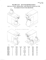
COFFEE BREWERS
OPERATION MANUAL
MODEL # GENERAL SPECIFICATIONS ELECTRICAL DATA
Width Depth Height
Ship wt.
(Ibs.)
Watts Volts Amps
BT2 - 2 Station Pourover 17 ½”
9 ½”
20 ¼” 26
1600
2200
120
220
13.3
10.0
BT2A - 2 Station Automatic 17 ½”
9 ½”
20 ¼” 26
1600
2200
120
220
13.3
10.0
BT3 - 3 Station Pourover 17 ½”
9 ½”
20 3/8” 27
1700
2300
120
220
14.2
10.5
BT3A - 3 Station Automatic 17 ½” 9 ½” 20 3/8” 27
1700
2300
120
220
14.2
10.5
WARNING: MACHINE WARRANTY IS VOID IF MACHINE IS CONNECTED TO ANY VOLTAGE OTHER THAN 120
VOLTS. (EXPORT UNITS SHOULD BE CONNECTED TO 220 VAC VOLTS.)
**INSTALLATION INSTRUCTIONS**
NOTE: A SEPARATE CIRCUIT SHOULD BE SUPPLIED FOR EACH OF THESE BREWERS WITH A 15 AMP.
CIRCUIT BREAKER OR FUSE. CHECK LOCAL CODES FOR COMPLIANCE IN INSTALLATION.
CAUTION: DO NOT CONNECT BREWER TO POWER SOURCE UNTIL AFTER PRIMING. (INSTRUCTION BELOW.)
CECILWARE CORPORATION 43-05 20th Avenue, Long Island City, NY 11105
N203A-5/98
1
CONTENTS
SPECIFICATIONS
INSTALLATION INSTRUCTIONS
BREWING INSTRUCTIONS
CLEANING INSTRUCTIONS
ADJUSTMENT INSTRUCTIONS
TROUBLE SHOOTING GUIDE
REPAIR PARTS LIST
WIRING DIAGRAM
WARRANTY
Every Cecilware product has been carefully inspected before shipment. The finest of materials and
the highest
standards of workmanship have been but into the equipment.
Within 1 year of purchase, should any Cecilware product show defect in factory workmanship or
material, we agree to
Repair, at our option or replace without cost to user such parts which prove upon factory inspection
to have been so
defective. All equipment must be shipped transportation charges prepaid for acceptance. This
warranty covers
replacement parts only, labor charges are covered for 90 days after installation.
This warranty does not apply under the following conditions:
• neglect or abuse of equipment
• excessive lime condition
• Improper installation
• any outside modification to equipment
Every Cecilware urn body is covered for three years. This warranty covers the stainless steel body
and stainless steel liners only.
Portable equipment such as Electric Fryers, Food Warmers, Electric Stoves, Dispensers, Plug-In
Urns, Coffee Brewers and Warmers must be returned to the factory or brought to an authorized
service station for repair.

WARNING: MACHINE WARRANTY IS VOID IF MACHINE IS CONNECTED TO ANY VOLTAGE OTHER
THAN 120 VOLTS. (EXPORT UNITS SHOULD BE CONNECTED TO 220 VAC VOLTS).
**INSTALLATION INSTRUCTIONS**
NOTE: A SEPARATE CIRCUIT SHOULD BE SUPPLIED FOR EACH OF THESE BREWERS WITH A 15 AMP. CIRCUIT
BREAKER OR FUSE. CHECK LOCAL CODES FOR COMPLIANCE IN INSTALLATION.
CAUTION: DO NOT CONNECT TO POWER SOURCE UNTIL AFTER PRIMING (INSTRUCTION BELOW).
WATER HOOK-UP (FOR AUTOMATIC BREWERS ONLY • BT2A, BT3A)
Automatic Brewers should be hooked up by a plumber in compliance with local plumbing codes. The National Sanitation Foundation (NSF) requires the following for NSF approved hook-up:
1. A quick disconnect Water connection or enough extra coiled tubing, (at least two times of the depth of brewer) so that brewer can be moved to clean underneath.
2. An approved ftowback prevention device such as a double check valve to be installed between brewer and water supply. You automatic coffee brewer was shipped with a water hook-
up kit consisting of a strainer, length of ¼” (outside diameter) copper tubing and water valve fitting which connects to valve in rear of brewer. This fitting needs to be finger tightened
only. Connect the open end of the strainer to ¼” O.D. tubing and a shut-off (supplied by others) leading to cold water supply. 20-120 PSI water pressure, required for proper operation.
CAUTION: These brewers are equipped with a rear Toggle Switch which controls the power supply to the Brewer. Toggle Switch must be in the down or "OFF' position until step (3) is
completed.
TO PRIME THESE INSTRUCTIONS ARE FOR INITIAL PRIMING ONLY AND DO NOT HAVE TO BE REPEATED FOR NORMAL OPERATION.
1. Remove sample filter pack from funnel and insert funnel back into machine.
2. Place an empty decanter on warmer plate directly under funnel.
3. Lift cover (69 Fig. 3) and pour 3 decanters of cold water through the top opening at 3 minute intervals. After the third decanter is poured, water will flow through spray head and funnel and
fill decanter beneath.
4. Plug line cord into receptacle and turn on power switch. The power light will light, indicating power is applied to the tank heater. Wait approximately 15 minutes for the water to reach
brewing temperature, at which point the green light will light. You are now ready to brew coffee.
**BREWING INSTRUCTIONS**
AUTOMATIC MODELS BT2A. BT3A
1. Make sure power switch and green ready light are on. (Wait for green ready light to come on if necessary).
2. Place paper filter in brew funnel. Open pack of fine grind coffee (as recommended by your coffee supplier) and spread evenly on filter paper.
3. Insert Brew funnel back into machine and place empty decanter under funnel.
4. Turn on warmer switch and press brew switch. Coffee will be ready in 3 1/2 minutes.
5. Adjust timer (if necessary to fill decanter to just below band on handle)-) refer to instructions for timer adjustment).
6. Remove grounds and filter as soon as coffee has dripped through. Never pour coffee back through spent grounds.
POUR-OVER MODELS (BT2. BT3)
1. Follow steps 1, 2 and 3 above.
2. Fill decanter with cold water to just below band on handle, lift cover (69, Fig.3), and pour water through top of screened opening. Place empty decanter under funnel.
3. Turn on left warmer switch above decanter. Coffee will be ready in 3 1/2 minutes.
4. Remove grounds and filter as soon as coffee has dripped through. Never pour coffee back through spent grounds.
BACK-UP SYSTEM (FOR AUTOMATIC BREWERS)
In case of solenoid or timer malfunction or water supply problems (clogged strainer), automatic models may be used as pourover units simply by lifting cover and pouring decanter through
screened top opening.
**CLEANING INSTRUCTIONS**
1. Wash brew funnel and decanter by hand as needed. Do not use dishwasher, which may cause decanter breakage.
2. For cleaning all metal surfaces, use any reputable stainless steel cleaning compound. Sprayhead should be checked and cleaned regularly. (At least once a week.) Sprayhead holes must
be kept open. To prevent "UMING" problems in the water tube and air tube, remove Sprayhead and insert spring probe all the way into the tank through both tubes. When inserted into tank
property, no more than two inches of the spring should be visible. Push back and forth five or six times. This will keep tubes open and clear of lime. In hard water areas, this should be done
every day; this takes less than a minute.
2

FOR AUTHORIZED SERVICE PERSONNEL ONLY
**SERVICE INSTRUCTIONS** and **TROUBLE SHOOTING GUIDE**
CAUTION: DISCONNECT POWER BEFORE ATTEMPTING ANY ELECTRICAL REPAIRS
THERMOSTAT ADJUSTMENTS:
NOTE: The thermostat adjustment knob (Item 15) is located in back of top box. If water temperature is less than 197°F (92°C) slowly turn thermostat knob clockwise until
ready light goes out. When temperature of water approaches 197° to 203°F (92° to 95°C) slowly turn thermostat knob counter-clockwise until the green ready light
comes on. If water temperature cannot be increased when thermostat knob is turned fully clockwise, then proceed as follows:
Remove Bracket and pull off knob. Place a small screwdriver into the center of thermostat shaft. While observing green ready light and temperature on thermometer, hold
shaft and turn small adjustment screw in center counter-clockwise until green ready light goes out. When temperature of water approaches 197°-203°F (92°-95°C),
slowly turn screw clockwise until ready light comes on. Turning screw clockwise towers temperature; counter-clockwise raises it. After adjusting center screw, place nail
polish or glyptol on screw to set in position.
NOTE: As a final check, measure water temperature at Spray Head (25, Fig 3). Temperature should be 197° to 203°F (92° to 95°C).
TIMER ADJUSTMENTS (Automatic Models BT2A, BT3A)
NOTE: Timer adjustment knob is located in back of top box. To increase volume of water, turn knob of timer clockwise. To decrease, turn knob counter-clockwise. Turn
knob by small increments.
NOTE: Timer must go through a complete cycle before another adjustment can be made. Timer cannot be adjusted once it has been initiated.
PROBLEMS WITH WARMER ELEMENTS & SWITCHES:
If warmer plate fails to heat, first check power source and then check if light on warmer switch (21 Fig 3) is lit when in the "1" position. If warmer switch is lit, replace
warmer plate by unplugging brewer, removing the two hold down screws on plate and withdrawing warmer plate from brewer. Replace the new warmer plate. If warmer
switch does not light, replace it. To remove switch press each tab behind front plate of brewer down with screwdriver in turn. As each tab is pressed, pop that corner of
warmer switch out of the front of brewer. New switch snaps in from the front.
IF WATER FAILS TO HEAT:
1. If Red power light (20 Fig 3) and warmer switches do not come on, check power source. Replace fuse or reset circuit breaker if necessary. If power is good, check rear
power switch for continuity and replace if switch stays open.
2. If water still fails to heat, disconnect line cord and check out tank heater (31 Fig 3), thermostat (14 Fig 3) and high temperature safety shutoff (54 Fig 3). Replace
needed parts.
MAINTENANCE ON AUTOMATIC MODELS BT2A. BT3A
IF NO WATER COMES FROM SPRAY HEAD AND POWER TO BREWER IS PRESENT CHECK:
1. Water Supply Line 2. Strainer/Filter
3. Solenoid 4. Timer
TESTING SOLENOID AND TIMER
Make sure brewer is property primed. Turn on power switch and then warmer switch above funnel. Press brew switch and hold for one minute. If solenoid buzzes and water flows through
spray head when brew switch is pressed and held, but slops when switch is released, timer is defective. Replace it. If no water flows from spray head, and solenoid is inactive, first check brew
switch and wiring to solenoid and replace as necessary. If brew switch and wiring are okay, solenoid is at fault.
REPLACING SOLENOID, TIMER, HI-UMIT, THERMOSTAT AND TANK HEATER (See III. 3)
Unplug power cord, shut off water supply (for automatic brewers) and remove top cover.
Solenoid (Item 1)- Remove electrical connections. (2) screws, water inlet fitting and silicone tubing. Replace with new solenoid.
Timer (Item 13) - Loosen and remove (2) screws in back of top box. Lift out timer and disconnect the color coded wires one by one and connect same to replacement timer. Place
pointer of knob to center and dial range.
Hi-Umit Switch (Item 54)- Disconnect the (2) push-on leads, loosen large nut on heating element terminal and pull out hi-limit bracket (Item 53). Replace switch (Hem 54).
Thermostat (Item 16)- Remove water tank insert (Hem 40), thermostat bulb clip (Item 48), hex nut (Item 42) from capillary tank fitting, thermostat knob guard (Hem 14), and (2) screws
securing thermostat to housing. Disconnect the push-on leads and remove thermostat. Replace with new one in reverse order. When installing new control, do
not over tighten small packing nut on compression fitting.
Tank Heater (Item 32)- Remove tank insert (Item 40), bulb clip (Hem 48), (2) hex nuts and washers. Disconnect push-on leads. Replace in reverse order.
3

Fig.1
REPLACEMENT PARTS UST FOR BT SERIES BREWERS
Item # Description Part # Where Used
1 Solenoid Valve L298A All Automat
2
Mounting Screen
#10
x ½” "A"
P050A
All Automat
Cad Prt'd.
3
Solenoid Fitting Gasket
M192A
All Automat
4
Solenoid Fi
tting
K178A
All Automat
5
Solenoid Tinnerman
P228A
All Automat
6
Switch Guard
U565V
9
Heater on/off switch
L069A
10
Filling Hose
M222J
All Automat
11
Hose Clamp
P216A
All Automat
12
#6
-
32
x
¼
Screw
P183A
13
Solid State Timer
L265A
All Automat
15
Thermostat Knob
M008A
16
Thermostat
L002A
17
#8
-
32
x
¼
Screw
P012A
19
3/8”
Grommet
M218A
20
Red Power Light
C260A
21
Wanner Switch
L155A
22
Brew Switch
L291A
All Automat
Brew Ready Light
L289A
BT2, 3
24
Spray Head Adapter
E007
25
Spray Head
E026A
26
Funnel Runner (Left) w/V000A
U550A
funnel
26
Funnel Runner (Left) W/V004A
U584A
funnel
27
Funnel Runner (Right)
W/V004A
U585A
funnel
27
Funnel Runner (Right) w/V000A
U562A
funnel
28
Bottom C
over
R393A
20
Rubber Foot
M134A
30
Mounting Screw
#6
-
32
x ½
P271A
31
318
x ¼ Brass FTG
K038A
32
Tank Heater
1
400W @
1
20V
G231A
33
Overlow Tube
H164A
34
Hose Clamp
P223A
36
Spray Tub
-
2
PC
H176Q
38
Top Cover
R396V
BT2
Top Cover
R
402V
BT
3,
3A
4
Item # Description Part# Where Used
40
Water Tank Insert
01410
BT2A, BT3A
40 Water Tank Insert 01340 BT2,BT3
41 Tank Cover Gasket M215A
42 ¼ x 18 ¾ Hexnut-BT K207A
47 Water Inlet Tub H168V
48 Thermostat Bulb Clip P143A All Automatic
44 Thermostat Guard U623A
49 Water Tank Q133A BT2, BT3
49
Water Tank
Q140A
BT2A, 3A
50
Stainless Steel Washer
P175A
51
Spray Head Gasket
M121A
52
#6
-
32
Tinnerman
P088A
53
Hi
-
Limit Bracket
U556E
54
Hi
-
Limit
L267A
61
Heyco Bushing
B012A
62
Line Cord
C998Q
63
Warmer Element Assembly
G095A
64
#6
-
32
x
¾”
Screw
P139A
65
Warmer Reflector
U485A
BT
3, 3A
66
Warmer Spacer
P205A
BT
3, 3A
67
5/8"
Grommet
M090A
68
Pour
-
Over Dish
U587Q
69
Cover Asse
mbly
U588Q
70
Knob
M010A
71
Chain
P291A
*NOT SHOWN
Cecilware Funnel (Standard)
V000A
Black
Brewmatic Funnel (Small)
V004A
Filter Paper for A
-
1
2
Filter Paper for A
-
10
Clean Out Spring (Small)
V161A

5

(J114) ELECTRICAL SCHEMATIC FOR BT BREWERS
SYM. Part Description P/N
DS1 Power Light C260A
K1 Solenoid L298A
K2 Timer Relay L265A
R1 Tank Heater G231A
W1 Left Warmer G097A
W2 Right Warmer G097A
W3 Top Warmer BT3, BT3A G097A
S1 Main Power Switch L069A
S3 Brew Cycle Control &
Left Warmer Switch
L155A
S4 Right Warmer Switch L155A
S5 Brew Switch BT2A,
BT3A
L291A
S6 Hi-Limit Switch L267A
S7 Thermostat 100-203
Degree F
L266A
BL Black Wire
WH White Wire
BR Brown Wire
Red Red Wire
Blue Blue Wire
Omit the following parts on BT2 and BT3 Units:
K1. K2.S5(Pins #1 and #2)
ELECTRICAL SCHEMATIC FOR BT BREWERS
6
/