Page is loading ...

2 Introduction
There are many applications where
it can be a benefit to operate the
Actuators using pressurised water
instead of compressed air. This
can be particularly useful in remote
areas where compressed air is
not available.
The most common situation is when
using mains water supply which is
normally in the pressure range from
60-100psi (4 - 7 bar).
Standard XL Actuators have been
used successfully in many water
applications but HYTORK
recommends that XLW Actuators are
used in this application to assure
smooth and reliable operation.
HYTORK XLW Actuators are
specifically prepared for operating by
water. This preparation is concerned
with corrosion protection, bearings
and the preventing the ingress of
particles with the water.
Contaminated water can cause
damage to the Actuator Seals and
bearing areas and reduce the
operating efficiency and Actuator life.
3 Corrosion
Protection
3.1 Aluminium Components.
Aluminium body components on
HYTORK’S standard XL Actuators are
treated with CERAMIGARD, a unique
Di-Aluminium Tri-Oxide (AL
2
O
3
) surface
treatment, which provides a hard,
corrosion resistant, ceramic-like
coating protecting all body parts
against wear and corrosion.
This CERAMIGARD finish is particularly
efficient in water applications and
many years of site experience with
Hytork
Dossier
Installation,
Operating and
Maintenance
Instructions
1
MAC099813
1
2
3
4
5
6
7
8
9
10
11
12
XLW Series
Water Operated
Actuators
Types: EDNW
EIAW
EDFW
Contents
Important Safety Procedures
Introduction
Corrosion Protection
DURASTRIP ‘W’ Bearings
Operating Media
Piping Instructions
Mounting and
Operating Instructions
Speed of Operation
Maintenance Requirements
Testing and Cycling of
Infrequently Used or
Stored Actuators
Spares Kits
Service
1 Important Safety
Procedures
When carrying out maintenance
on XLW Actuators follow the
specific XLW instructions given in
this Dossier (MACxxxxx1) and the
general XL instructions given in
Hytork I, O & M Dossier
MACxxxxx1.
Qualified maintenance personnel
should read and follow these
straightforward instructions.
Always disconnect the Air or
alternative Operating Pressure and
Electrical Supplies before carrying
out any form of maintenance on
an Actuator.
On Spring Return models always
contain the Spring Tension with
HYTORK Retractor Rods as explained
in HYTORK Dossier MACxxxxx1.
Follow instructions for using the
Retractor Rod carefully.
Never attempt to remove the pistons
from the Actuator body by using air
or other pressure mediums when the
End Caps have been removed.
Do not shorten or distort the
SAFEKEYS; correct length SAFEKEYS
are supplied with the Spares Kit.
When replacing items use only
HYTORK authorised components.
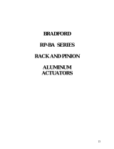
Numbers in brackets (#) refer to parts
on the exploded XLW diagram (Fig. 1).
Read the relevant sections
carefully before continuing.
Installation, Operating and Maintenance Instructions XLW Series Water Operated Actuators MAC099813
Quality
Assured
registered
management
systems
to ISO 9001

1
2
bm
bm
bm
bobpbq
bobp
br
bs
bt
bt
bk
9
9
7
8
7
6
3
4
2
2
2
bl
bn
bn
5
bs
Fig. 1
Double
Acting
Spring
Return
water operation and water in air lines
has shown excellent protection
against corrosion.
3.2 Pinion. (4)
The finish on the Pinion will, in most
cases, be the standard XL treatment.
There are certain applications (as with
high chlorine concentrations, for
example) where one of the HYTORK
CORROGARD Fluropolymer
treatments may be more suitable.
HYTORK will be pleased to give exact
details of the finish required once the
specification of the water is known.
3.3 Spring Return Actuators.
The Springs are protected by an
Electro Phoretic finish as standard.
3.4 External Surface Finish.
The externals of all XLW Actuators
are treated with a long cure, two part
epoxy coating to provide extra
protection against aggressive
environments.
Differences between
Part the Standard XL
No. Component Quantity and XLW Models
1 Travel stops & Seals 2 Standard XL
2 End Caps 2 Standard XL
3 Pistons 2 Standard XL
4 Pinion 1 Standard XL or
CORROGARD Finish
5 Body 1 Standard XL
6 SAFEKEY & ‘O’ Rings 2 Standard XL
Differences between Standard XL and XLW Actuators
Differences between
Part the Standard XL
No. Component Quantity and XLW Models
7 Springs* 2, 3 or 4 Standard XL
8 Retractor Caps* 2 Standard XL
9 Pinion Radial Bearings 2 DURASTRIP ‘W’
bk Piston Bearings 2 DURASTRIP ‘W’
bl Piston ‘O’ Rings 2 Standard XL
bm End Cap ‘O’ Rings 2 Standard XL
bn Pinion ‘O’ Rings 2 Standard XL
bo Thrust Bearings 2 DURASTRIP ‘W’
bp Steel Thrust Washers 2 Standard XL
bq Snap Ring (Circlip) 1 Standard XL
br Position Indicator 1 Standard XL
bs Sealing ‘O’ Ring* 2 Standard XL
bt Sealing Bolts* 2 Standard XL
*Spring Return models only
2

4 DURASTRIP
‘W’ Bearings
Continuous immersion in water will
cause the standard XL Bearing to
wear prematurely. To maximise
Actuator Bearing life DURASTRIP
‘W’ Bearings are used.
5 Operating Media
5.1 Operating Media.
XLW Actuators can be operated by
clean air or filtered water. The water
must be clean and free from any
particles that could damage the Seals
or score the Actuator cylinders.
Solenoid directional control Valves
require a clean operating media and
any form of contamination may cause
the spool to stick.
5.2 Water Filtration.
It is recommended that a filter of
10 microns be used on all water
supplies. Failure to use clean water
will reduce Actuator life and may
cause malfunction of both the
Actuator and directional control Valve.
5.3 Maximum
Operating Pressure.
XL models 45 to 2585
Do not exceed 8.3 bar (120 psi).
XL models 4580
Do not exceed 7 bar (100 psi).
The normal XL operating pressures
should be adhered to unless HYTORK
has given specific authorisation in
writing that this may be increased.
The fact that water is virtually
incompressible means that it may be
possible to utilise higher pressures in
certain applications. If you have an
application where higher operating
pressures are required please consult
HYTORK with full details for an
assessment to be made.
Fig. 2a
Fig. 2b
6 Piping
Instructions (Fig. 2a & 2b)
All Actuators can be either piped with
solid or flexible tubing with the
Solenoid Valve mounted remotely
from the Actuator or by mounting the
Solenoid DIRECTLY onto the NAMUR
mounting pad on the side of the
Actuator. (ONLY Solenoids made to
the NAMUR standard can be mounted
in this way.)
6.1 Solenoid Valves.
Care must be taken to ensure that
Solenoid directional control Valves
used on water applications are
designed for this purpose. For the
best possible performance it is
recommended that the internal
porting of Solenoid Valves is as
large as possible.
6.2 Direct Acting Low Cv
Solenoid Valves.
Low Cv (direct acting) Solenoid Valves
must not be used even on small
Actuators as the small port sizes and
low spring forces used in this design
of Valve will cause problems.
6.3 HYTORK CATS
Solenoid valves.
The CATS Solenoid Valve MUST NOT
BE used on water applications with
Spring Return Actuators. The Spring
chamber must be allowed to vent to
atmosphere.
7 Mounting
and Operating
Instructions (Refer to Fig. 1)
7.1 Actuator to Valve Installation.
The mounting hole sizes and bolt hole
circle of the holes are to ISO 5211.
These holes are ISO METRIC COARSE
on metric models (UNC COARSE on
USA models) as standard. When
mounting the Actuator to a Valve
using a Mounting Kit, the Pinion drive,
coupling device and Valve stem
should be centred and concentric
to prevent any side loading to the
bottom Pinion Radial Bearing.
Ensure that the square shaft or drive
adaptor to be operated is a close, but
free sliding fit, to the female drive in
the Actuator shaft (4).
8 Speed
of Operation
Water used as the operating medium
reduces the operating speed
considerably. The actual time will
depend on the Cv of the Solenoid
Valve used and the friction losses
along the pipe. Small diameter and/or
long pipes will increase these losses
and reduce operating speeds
significantly.
8.1 Speed control.
Water is virtually incompressible
which makes it ideal for accurate
speed control. Always ensure that
any speed adjustment is of the
exhaust water.
3

MAC099813
9 Maintenance
Requirements
It is recommended that XLW
Actuators that have been operated by
water be overhauled after 250,000
cycles. Follow the instructions in
HYTORK DOSSIER MACxxxxx1 and
ask for the XLW Spares Kit.
9.1 Spares Recommendations.
When disassembling and carrying out
maintenance work on an XLW
Actuator, HYTORK recommends that
a HYTORK XLW Spares Kit is used
replacing all ‘O’ Rings, DURASTRIP
Bearings, washers etc. This kit is only
available from HYTORK or its
Stocking Distributors.
10 Testing and
Cycling of
Infrequently
Used or Stored
Actuators
Actuators not in current use (ie:
Actuators in stores or stock and/or
not operated for at least a 3 month
period), should be cycled a minimum
of ten times and tested against the
possible ‘pre-set’ of the seals.
11 Spares Kits
XLW Actuators
Contents List:
1 x I, O & M (XL) Instructions
1 x I, O & M (XLW) Instructions
2 x SAFEKEY Assemblies (6)
2 x SAFEKEY Seal ‘O’ Rings (6)
2 x Piston DURASTRIP ‘W’ Bearing
Strips (10)
2 x Steel Thrust Washers (15)
1 x Pinion top ‘O’ Ring (13)
1 x Pinion top DURASTRIP ‘W’
Radial Bearing Strip (9)
2 x DURASTRIP ‘W’ Thrust
Bearing (14)
1 x Pinion bottom ‘O’ Ring (13)
1 x Pinion bottom Radial
DURASTRIP ‘W’ Bearing (9)
2 x Stop Seals (1)
2 x Piston ‘O’ Rings (11)
2 x End Cap ‘O’ Rings (12)
1 x Pinion Snap Ring
(Circlip) (16)
12 Service
It is the policy of HYTORK to give
the best possible service to our
customers. We are happy to assist
you in any way we can and if you
have any questions about HYTORK
Actuators or other HYTORK Products
please do not hesitate to contact one
of HYTORK’S VALVE AUTOMATION
CENTERS or your local HYTORK
Stocking Distributor.
4
UK Patents:
GB 2 102 887 B;
GB 2 123 517 B;
GB 2 138 505 B;
GB 2 216 229 B;
GB 2 225 079 B;
GB 2 229 254 B;
GB 2 253 459 B;
GB 2 268 574 B.
US Patents:
4,496,071;
4,651,627;
4,716,815.
Warranties:
Unauthorised
modification to
any Hytork
Product totally
invalidates all
warranties.
Important:
We have endeavoured
in this publication to
make the contents as
accurate as possible,
but being given as
general information, it
is not to be taken as
binding unless
specifically confirmed
in writing. Due to
Hytork's continuing
commitment to
engineered product
advancement, the
product specifications
and data presented in
this publication are
subject to change
without notice.
Hytork Controls Inc.
Valve Automation Center Tel: [+1] (813) 630 2255
9009 King Palm Drive Fax: [+1] (813) 630 9449
Tampa, Florida 33619 Email: [email protected]
USA http://www.hytork.com
Hytork Controls Australian Operations
25 South Street Tel: [+61] (2) 9841 2414
Rydalmere Fax: [+61] (2) 9684 6439
NSW 2116 Email: [email protected]
Austalia http://www.hytork.com
Hytork Controls Europe
Valve Automation Center
6 Bracken Hill
Southwest Industrial Estate Tel: [+44] (0191) 5180020
Peterlee Fax: [+44] (0191) 5180032
County Durham Email: [email protected]
SR8 2LS UK http://www.hytork.com
Hytork Controls Europe
Ryeford Road South
Kings Stanley Tel: [+44] (01453) 827710
Stonehouse Fax: [+44] (01453) 827714
Gloucestershire Email: [email protected]
GL10 3HG UK http://www.hytork.com
Part of the Hytork International plc Group
Quality
Assured
registered
management
systems
to ISO 9001
/