General Monitors 2602A Zero Two Series Control Module for H2S Applications Owner's manual
- Category
- Carbon monoxide (CO) detectors
- Type
- Owner's manual

Model 2602A
Zero Two Series Control for
Hydrogen Sulfide Gas
App
lications
The information and technical data disclosed in
this document may be used and disseminated
only for the purposes and to the extent
specifically authorized in writing by General
Monitors.
Instruction Manual 12-05
General Monitors reserves the right to change
published specifications and designs without
prior notice.
MAN2602A
Part No. MAN2602A
Revision F/12-05

2602A
ii
This page intentionally left blank

2602A
Table of Contents
TABLE OF FIGURES...................................................................................................................V
TABLE OF TABLES....................................................................................................................VI
INTRODUCTION ..........................................................................................................................1
Protection for Life....................................................................................................................................1
Special Warnings....................................................................................................................................1
Customer Support...................................................................................................................................1
Commissioning Safety Systems .............................................................................................................2
1.0 BEFORE INSTALLATION......................................................................................................3
1.1 General Description ...................................................................................................................3
1.2 Features & Benefits....................................................................................................................4
1.3 Applications................................................................................................................................4
2.0 INSTALLATION......................................................................................................................5
2.1 Upon Receipt of Equipment.......................................................................................................5
2.2 Control Module Installation ........................................................................................................5
2.3 Rear Terminal Connections .......................................................................................................6
2.3.1 A2 Alarm .......................................................................................................................6
2.3.2 A1 Alarm .......................................................................................................................7
2.3.3 Fault Alarm....................................................................................................................8
2.4 Sensor Location Considerations..............................................................................................11
2.5 Sensor Poisons........................................................................................................................12
2.6 Applying Power........................................................................................................................12
3.0 OPERATION.........................................................................................................................14
3.1 General Maintenance...............................................................................................................14
3.2 Electrical Inputs........................................................................................................................14
3.3 Electrical Outputs.....................................................................................................................14
3.4 Accepting Alarm Conditions.....................................................................................................15
3.5 Resetting Latched Alarms........................................................................................................16
3.5.1 LED Test.....................................................................................................................16
3.6 CAL/INH Open Collector..........................................................................................................17
3.7 4.7Card Test Feature...............................................................................................................17
3.8 Fault Diagnostics......................................................................................................................17
4.0 USER INTERFACES............................................................................................................19
4.1 Types of User Interfaces..........................................................................................................19
4.2 Calibration Check Mode...........................................................................................................20
4.3 Calibration Mode......................................................................................................................21
4.4 Setup & Setup Check Modes...................................................................................................25
4.5 Inhibit Mode..............................................................................................................................35
5.0 CUSTOMER SUPPORT.......................................................................................................37 T
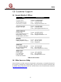
5.1 General Monitors’ Offices.........................................................................................................37
5.2 Other Sources of Help..............................................................................................................37
iii

2602A
iv
6.0 APPENDIX A........................................................................................................................38
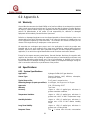
6.1 Warranty...................................................................................................................................38
6.2 Specifications...........................................................................................................................38
6.2.1 System Specifications.................................................................................................38
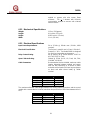
6.2.2 Mechanical Specifications...........................................................................................39
6.2.3 Electrical Specifications..............................................................................................39
6.2.4 Environment Specifications.........................................................................................40
6.3 Engineering Specifications.......................................................................................................40
6.3.1 Zero Two System........................................................................................................40
6.3.2 2602A Control Module................................................................................................40
6.4 Sensor Assembly/Accessories.................................................................................................41
6.4.1 Sensing Elements.......................................................................................................41
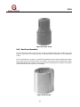
6.4.2 Sensor Housing...........................................................................................................43
6.4.3 Splash Guard..............................................................................................................43
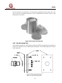
6.4.4 Dust Guard Assembly.................................................................................................44
6.4.5 Duct Mounting Plate....................................................................................................45
6.4.6 Calibration Equipment.................................................................................................46
7.0 APPENDIX B........................................................................................................................48
7.1 Glossary of Terms....................................................................................................................48
8.0 APPENDIX C........................................................................................................................50
8.1 Engineering & Technical Drawings..........................................................................................50
8.1.1 Reference Drawing # 11141.......................................................................................50
8.1.2 Reference Drawing # 11140-1....................................................................................51
9.0 APPENDIX D........................................................................................................................52
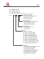
9.1.1 Ordering Information...................................................................................................52
10.0 APPENDIX D ............................................................................................................53
10.1 Zero Two Series Modules........................................................................................................53
INDEX.........................................................................................................................................55

2602A
v
Figure 27: A1 Latching/Non-Latching Alarm Option.............................................................................................31
Table of Figures
Figure 1: Model 2602A...........................................................................................................................................3
Figure 2: Control Module Coding Strip...................................................................................................................5
Figure 3: Wire Strip Length.....................................................................................................................................6
Figure 4: Rear Terminal Designations....................................................................................................................6
Figure 5: Protection Circuit for Relay Contacts......................................................................................................8
Figure 6: Typical External Circuits for Open Collectors..........................................................................................9
Figure 7: Sensor/Controller Connections .............................................................................................................10
Figure 8: Card Test Switch Wiring........................................................................................................................10
Figure 9: Analog Signal Connections...................................................................................................................11
Figure 10: Power Connections for Rear Chassis.................................................................................................13
Figure 11: Front Panel Display.............................................................................................................................19
Figure 12: Breaker Bottle Operation.....................................................................................................................20
Figure 13: Entering the CAL Check Mode............................................................................................................20
Figure 14: Breaker Bottle Operation.....................................................................................................................22
Figure 15: Entering the CAL Mode.......................................................................................................................22
Figure 16: AC Display During CAL Mode.............................................................................................................23
Figure 17: CP Display during CAL Mode..............................................................................................................24
Figure 18: CC Display During CAL Mode.............................................................................................................24
Figure 19: F7 Display During Cal Mode...............................................................................................................25
Figure 20: Entering the Setup & Setup Check Modes..........................................................................................26
Figure 21: Entering the Password........................................................................................................................27
Figure 22: Entering Inhibit Mode ..........................................................................................................................28
Figure 23: A2 Energized/De-Energized Alarm Option..........................................................................................29
Figure 24: A2 Latching/Non-Latching Alarm Options...........................................................................................29
Figure 25: A2 Alarm Set Point Option ..................................................................................................................30
Figure 26: A1 Energized/De-Energized Alarm Option..........................................................................................30
Figure 28: A1 Alarm Set Point Option ..................................................................................................................31
Figure 29: Fault/Inhibit Mode................................................................................................................................32
Figure 30: Entering Card test Options..................................................................................................................33
Figure 31: Card Test Ramp Time, 3/10 Seconds.................................................................................................33
Figure 32: Alarm Output Option During a Card Test, AC/nA ...............................................................................34
Figure 33: Password Enabled/Disabled Option....................................................................................................34
Figure 34: Entering a New Password...................................................................................................................35
Figure 35: MOS Sensor Diagram, Top View........................................................................................................41
Figure 36: MOS Sensor Cut-Away, Side View.....................................................................................................42
Figure 37: Universal Sensor Housing...................................................................................................................43
Figure 38: Splash Guard ......................................................................................................................................44
Figure 39: Dust Guard..........................................................................................................................................44
Figure 40: Dust Guard Assembly Kit....................................................................................................................45
Figure 41: Duct Mounting Plate............................................................................................................................45
Figure 42: Outline & Terminal Connections .........................................................................................................50
Figure 43: Final Assembly....................................................................................................................................51

2602A
Table of Tables
Table 1: A2 Terminal Designations ........................................................................................................................7
Table 2: A2 Alarm Relay Contacts .........................................................................................................................7
Table 3: A1 Alarm Terminal Designations..............................................................................................................7
Table 4: Fault Terminal Designations.....................................................................................................................8
Table 5: Unaccept and Calibration/Inhibit Terminal Designations .........................................................................9
Table 6: Sensor Wire Terminal Designations.........................................................................................................9
Table 7: Card Test Terminal Designations...........................................................................................................10
Table 8: Analog Output Terminal Designations....................................................................................................11
Table 9: Set Up Options.......................................................................................................................................36
Table 10: GM Locations .......................................................................................................................................37
vi

2602A
Introduction
Protection for Life
General Monitors’ mission is to benefit society by providing solutions through industry leading
safety products, services, and systems that save lives and protect capital resources from the
dangers of hazardous flames, gases, and vapors.
This manual provides instruction for installing and operating the General Monitors’ Model
2602A for Hydrogen Sulfide Gas Applications. While the 2602A system is easy to install and
operate, this manual should be read in full and the information contained herein understood
before attempting to place the system in service.
The safety products you have purchased should be handled carefully and installed, calibrated,
and maintained in accordance with the respective product instruction manual. Remember these
products are for your safety.
Special Warnings
Hydrogen Sulfide (H
2
S) is an extremely toxic gas, and exposure may result in a loss of
consciousness or death.
All Zero Two Series Modules contain components that can be damaged by static electricity.
Special care must be taken when wiring the system to ensure that only the connection points
are touched.
Only MOS (Metal Oxide Semiconductor) sensors designed by General Monitors will work with
the Model 2602A. Any attempt to use a sensor that has not been designed by General Monitors
will void the warranty.
Installation and Maintenance must be carried out by suitably skilled and competent personnel
only.
The display range must be selected at the factory and cannot be changed in the field. If the
display range on the Model 2602A needs to be changed, it will be necessary to return the
module to the factory.
Full backwards compatibility can be specified at the time of order. If this configuration is
specified, the rear terminal output designations will be identical to the previous generation of
Zero Two Series Modules.
Customer Support
For additional product information not contained in this manual, please contact General
Monitors Customer Support (Section
5.0).
1

2602A
NOTE: Each H
2
S sensor is shipped with a red plastic cap fitted over the sensor head. Inside
the cap is a desiccant. DO NOT remove this cap until you are ready to power the
system. SAVE the cap and RE-CAP the sensor anytime the system power is off for
more than one hour.
Commissioning Safety Systems
Before power up, verify wiring, terminal connections and stability of mounting for all integral
safety equipment including, but not limited to:
• Power supplies
• Control modules
• Field detection devices
• Signaling / output devices
• Accessories connected to field and signaling devices
After the initial application of power (and any factory specifies warm-up period) to the safety
system, verify that all signal outputs, to and from devices and modules, are within the
manufacturers’ specifications. Initial calibration / calibration checking / testing should be
performed per the manufacturers’ recommendations and instructions.
Proper system operation should be verified by performing a full, functional test of all component
devices of the safety system, ensuring that the proper levels of alarming occur.
Fault/Malfunction circuit operation should be verified.
2

2602A
1.0 Before Installation
This chapter provides a brief description of the Model 2602A, its features & benefits and a list of
some of its applications. More detailed information on the features and benefits in Section 1.2
will be presented in later chapters.
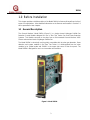
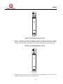
1.1 General Description
The General Monitors’ Model 2602A (Figure 1) is a single channel Hydrogen Sulfide Gas
Detection Control Module designed for use in Zero Two Series Gas and Flame Detection
Systems. This Module connects to the wires from a field mounted General Monitors’ MOS
Sensor and monitors levels of Hydrogen Sulfide Gas.
The Model 2602A is electrically and physically compatible with the other gas detection, flame
detection and system modules in the Zero Two Series. It is distinguished from the other
modules by its yellow border and “2602A" in the upper right corner of the front panel. The
Model 2602A is designed for use in non-hazardous environments.
Figure 1: Model 2602A
3

2602A
1.2 Features & Benefits
Single Point Auto calibrate: The unit’s display indicates simple automated calibration prompts
to the operator. Microprocessor Based Electronics: monitors fault conditions, sensor inputs, and
provides outputs in the form of display codes, analog signal, relay contact, and open collector
activations.
Calibration Check Mode: Verifies the integrity of the sensor by allowing the operator to apply
a test gas and view the response on the display.
Setup Mode: Allows the user to set parameters, such as, alarm output options, test options,
etc. These parameters are viewed on the display during the Setup Mode.
Password Option: Prevents unauthorized alteration of the setup parameters (can be
disabled).
Setup Check Mode: Allows the user to view the parameters that have been set by the factory
and/or an operator.
LED Test: Tests the integrity of each backlit LED and each segment of the digital display on
the front panel.
Card Test: Tests the functionality of the card through the microprocessor ramping up the signal
from 0 to full-scale.
Live Insertion/Removal: Allows the user to insert or remove a module while power is applied
to the system without damage to any of the components in the system.
1.3 Applications
The General Monitors Model 2602A is a Hydrogen Sulfide Gas Control Module designed for
Zero Two Series Applications. Below is a partial list of applications:
• Refineries
• Drilling platforms and rigs
• Gas and oil production platforms
• Gas collection facilities
• Mud-logging operations
• Sulfur recovery plants
• De-Sulfurization facilities
• Sewage disposal/treatment plants
• Chemical plants
4

2602A
2.0 Installation
This chapter discusses what to do when a Model 2602A is received, the terminal connections &
designations, sensor location considerations and what to be aware of when applying power.
2.1 Upon Receipt of Equipment
All equipment shipped by General Monitors is packaged in shock absorbing containers, which
provide considerable protection against physical damage. The contents should be carefully
removed and checked against the packing slip. If any damage has occurred, or if there is any
discrepancy in the order, notify General Monitors as soon as possible. All subsequent
correspondence with General Monitors must specify the equipment part and serial numbers.
Each Model 2602A is completely checked at the factory; however, a complete checkout is
necessary upon initial installation and start-up to ensure system integrity.
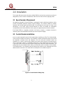
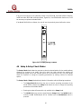
2.2 Control Module Installation
A rack or panel mounted chassis will be required when installing any Zero Two Series Module.
These chassis should be mounted in non-hazardous, weather-protected locations and should
be subjected to minimal shock and vibrations. The rack and panel mounted chassis are
available in 4, 8, and 16 channel sizes. Multiple 16-channel chassis may be connected to each
other to form larger systems. In installations where two or more module types are to be mixed
in the same chassis, ensure that the individual coding strips match the channel application. The
coding strips are pre-configured at the factory and the male portion is already on each module.
The female portion, if un-mounted, must be fastened into position on the mounting strip of the
desired chassis channel so as to mate with its counterpart on the module (
Figure 2).
Figure 2: Control Module Coding Strip
5

2602A
Zero Two series modules require air circulation to avoid excessive heat build-up. If chassis are
stacked vertically within an enclosure, forced air circulation may be required. The Control
Modules are, to a great extent, immune to electromagnetic interference (EMI). However, they
should not be mounted in close proximity to radio transmitters or similar equipment.
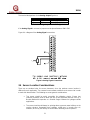
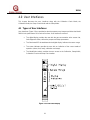
2.3 Rear Terminal Connections
All wire connections to the Model 2602A are made to the terminal block located at the rear of
the chassis. The terminal block accepts 16 AWG to 20 AWG, stranded or solid core wire. 14
AWG wire may be used if it is properly stripped according to
Figure 3.
Contact with PC Board components should be avoided in order to prevent damage by static
electricity.
Figure 3: Wire Strip Length
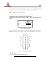
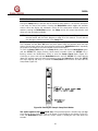
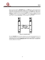
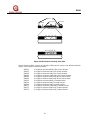
To connect wires to the terminal block on the Model 2602A, loosen the desired screw, insert
the stripped end of the wire and tighten. For the rear terminal designations refer to
Figure 4
below:
A2-C1
A1-C1
A2-1 A1-1
A2-2 A1-2
A2-3
A1-3
A2-4 A1-4
A2-C2 A1-C2
A2-OC
A1-OC
CT
F-C
UA-OC
F-1
AO+
F-2
AO-
LA1
RED
WHT
N/C
FUA/+24Vdc
F-OC
LA2
GRN
BLK
N/C
CAL-INH/COM
Figure 4: Rear Terminal Designations
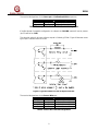
2.3.1 A2 Alarm
The terminal designations for the A2 alarm outputs are:
Label Term Description
6

2602A
7
A2-C1 2d Relay Common (1 & 2)
A2-1 4d Relay Contact
A2-2 6d Relay Contact
A2-3 8d Relay Contact
A2-4 10d Relay Contact
A2-C2 12d Relay Common (3 & 4)
A2-OC 14d Open Collector (OC)
LA2 24z OC Logic for A2 LED
Table 1: A2 Terminal Designations
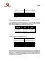
The A2 alarm outputs are DPDT relays, 1 open collector output (A2-OC) that follows the logic
of the relays and 1 open collector output (LA2) that follows the blinking pattern of the front
panel LED. The A2-C1 designation is common for A2-1 & A2-2.
The A2-C2 designation is common for A2-3 & A2-4. The normally open (NO) and normally
closed (NC) contacts depend on a user selectable option (Section
4.0). Table 2 refers to the
proper open and closed A2 alarm relay contacts while the unit is on power:
User Selected
Relay State
Normally
Open
Normally
Closed
Normally
Energized
A2-C1 & A2-1,
A2-C2 & A2-4
A2-C1 & A2-2,
A2-C2 & A2-3
Normally
De-Energized
A2-C1 & A2-2,
A2-C2 & A2-3
A2-C1 & A2-1,
A2-C2 & A2-4
Table 2: A2 Alarm Relay Contacts
2.3.2 A1 Alarm
The terminal designations for the A1 Alarm outputs are:
Label Term Description
A1-C1 2z Relay Common (1 & 2)
A1-1 4z Relay Contact
A1-2 6z Relay Contact
A1-3 8z Relay Contact
A1-4 10z Relay Contact
A1-C2 12z Relay Common (3 & 4)
A1-OC 14z Open Collector (OC)
LA1 24d OC Logic for A1 LED
Table 3: A1 Alarm Terminal Designations
The A1 Alarm outputs are DPDT relays, 1 open collector output (A1-OC) that follows the logic
of the relays and 1 open collector output (LA1) that follows the blinking pattern of the front
panel LED. The A1-C1 designation is common for A1-1 & A1-2. The A1-C2 designation is
common for A1-3 & A1-4. The normally open (NO) and normally closed (NC) contacts depend
on a user selectable option (Section
4.0).

2602A
8
Table 3 refers to the proper open and closed A1 alarm relay contacts while the unit is on
power.
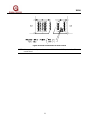
2.3.3 Fault Alarm
The terminal designations for the Fault outputs are:
Label Term Description
F-C 16z Relay Common
F-1 18z Relay Contact (NO)
F-2 20z Relay Contact (NC)
F-OC 22z Open Collector (OC)
FUA 32d Open Collector (OC)
Table 4: Fault Terminal Designations
The Fault outputs are SPDT relays, 1 open collector output (F-OC) that follows the logic of the
relays and 1 open collector output (FUA) dedicated to new fault indications. If the Backwards
Compatible configuration is ordered, the FUA will not be present (pin 32d will be for +24Vdc).
The Fault outputs are always normally energized when power is applied to the module.
The contact ratings for the A2 & A1 alarm and Fault relays are 4A @ 250Vac, 3A @ 30 Vdc,
Resistive, maximum.
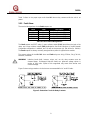
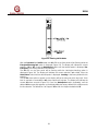
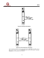
WARNING: Inductive loads (bells, buzzers, relays, etc.) on dry relay contacts must be
clamped down. Unclamped inductive loads can generate voltage spikes in
excess of 1000 volts. Spikes of this magnitude may cause false alarms and
contact damage.
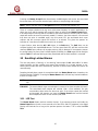
Figure 5 shows relay protection circuits that are recommended for AC and DC loads.
Figure 5: Protection Circuit for Relay Contacts

2602A
The terminal designations for the Unaccept and Calibration/Inhibit outputs are:
Label Term Description
UA 18d Open Collector Output
CAL/INH 32z Open Collector Output
Table 5: Unaccept and Calibration/Inhibit Terminal Designations
If the Backwards Compatible configuration is ordered, the CAL/INH output will not be present
(pin 32z will be for COM).
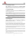
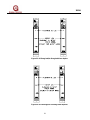
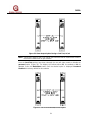
The electrical rating for all open collector outputs is 100mA @ 35Vdc.
Figure 6 illustrates some
typical open collector external circuits.
Figure 6: Typical External Circuits for Open Collectors
The terminal designations for the Sensor Wires are:
Label Term Description
RED 26d Red Sensor Wire
GRN 26z Green Sensor Wire
WHT 28d White Sensor Wire
BLK 28z Black Sensor Wire
Table 6: Sensor Wire Terminal Designations
9

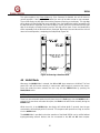
2602A
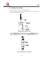
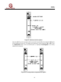
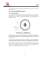
Figure 7 illustrates the Sensor/Controller connections.
Figure 7: Sensor/Controller Connections
The terminal designation for the Card Test Input is:
Label Term Description
CT 16d Switch Connection
Table 7: Card Test Terminal Designations
The Card Test Input is provided so that the user can access the Card Test feature remotely.
One end of a normally open SPST switch is connected to this termination and the other end is
connected to system common. To activate the feature, simply press and hold the switch for as
long as the test time is to be run.
Figure 8 is a block diagram that shows the switch connections
for the Card Test feature.
Figure 8: Card Test Switch Wiring
10

2602A
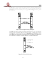
The terminal designations for the Analog Output Signal are:
Label Term Description
AO+ 20d Analog Signal (plus)
AO- 22d Analog Signal (minus)
Table 8: Analog Output Terminal Designations
If the Analog Signal is not used, a jumper must be placed between 20d & 22d.
Figure 9 is a diagram of the Analog Signal connections.
Figure 9: Analog Signal Connections
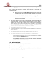
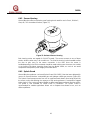
2.4 Sensor Location Considerations
There are no standard rules for sensor placement, since the optimum sensor location is
different for each application. The customer must evaluate conditions at the sensor site in order
to make this determination. The following are some general considerations:
• The sensor should be easily accessible for calibration checks. Ensure that
sufficient clearance exists to allow the use of field calibration devices such as a
Breaker Bottle with Ampoules or a Portable Purge Calibrator for hydrogen sulfide
applications.
• The sensor head should always be pointing down to prevent water build up on the
sensing element. Remember that hydrogen sulfide gas is heavier than air;
however, do not rely too heavily on this fact when selecting a sensor position.
11

2602A
12
• The sensor should be located in areas where leaks are suspected (i.e. near valves
& pipe connections, etc.).
• The sensor should not be placed where contaminating substances may coat it.
2.5 Sensor Poisons
Sensors may be adversely affected by prolonged exposure to certain atmospheres. The more
important poisons are:
• Halides (F
2
, Cl
2
, Br
2
, I
2
)
• Glycol
• Heavy Metals (e.g. Tetraethyl lead)
• Silicones contained in greases or aerosols are the most common “coating” agents,
which are not true sensor poisons, but reduce sensor response.
Other damaging materials, which attack the sensor physically, include mineral acids and
caustic vapors. The presence of such poisons and vapors does not exclude the use of MOS
sensors, however, a careful analysis of ambient conditions should be undertaken and the
customer should be aware that sensor calibration might need to occur at more frequent
intervals.
NOTE: Each H
2
S sensor is shipped with a red plastic cap fitted over the sensor head. Inside
the cap is a desiccant. DO NOT remove this cap until you are ready to power the
system. SAVE this cap and RE-CAP the sensor, anytime system power is off for more
than one hour.
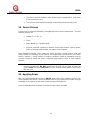
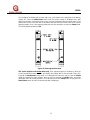
2.6 Applying Power
Zero Two Series Modules do not have an ON/OFF power switch. Each module in the Zero Two
Series operates from 24Vdc. Current requirements will vary according to the number and type
of modules in the system, as well as the number and type of field devices.
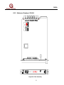
Figure 10 indicates where the power connections for the chassis are made.

2602A
Figure 10: Power Connections for Rear Chassis
NOTE: If the application of power does not turn ON the Model 2602A, check fuse F1 on the
control board.
13

2602A
3.0 Operation
This chapter discusses what general maintenance to perform, describes the electrical inputs,
outputs, accepting & resetting alarm & fault conditions and fault diagnostics.
3.1 General Maintenance
Once the Model 2602A has been installed, very little maintenance is required other than
periodic checks to verify the integrity of the system.
The user should evaluate conditions at the sensor site to determine how frequent calibration
checks should be performed.
A functional test of the system should be performed at least once each year. This test should
include full operation of stand-by systems or back up power for the prescribed period.
The power, sensor and output wiring should be checked for tightness, verifying that all of the
components and devices are connected correctly.
If the “Password” is disabled, periodic checks of the setup parameters should be performed.
3.2 Electrical Inputs
There are two electrical inputs to the Model 2602A. They are, the General Monitors’ MOS
Sensor (field device) and the Card Test input. Both of these input connections (sensor and
card test) are made to the rear terminal block (see Section
2.0 for more detailed installation
information).
The MOS Sensor input consists of the standard four lead connections used with General
Monitors MOS Sensors. The Black and White leads are dedicated to the heater circuit while the
Red and Green leads are dedicated to the sensing electrodes.
The Card Test input consists of a single termination for remote testing of the Model 2602A’s
functions. For detailed information on the Card Test, refer to
Figure 8.
3.3 Electrical Outputs
The electrical outputs on the Model 2602A consist of relay contacts, open collectors and an
analog current signal.
The following outputs have rear terminal relay contacts:
• A1 Alarm - DPDT relay contacts
• A2 Alarm - DPDT relay contacts
• Fault - SPDT relay contacts
14
Page is loading ...
Page is loading ...
Page is loading ...
Page is loading ...
Page is loading ...
Page is loading ...
Page is loading ...
Page is loading ...
Page is loading ...
Page is loading ...
Page is loading ...
Page is loading ...
Page is loading ...
Page is loading ...
Page is loading ...
Page is loading ...
Page is loading ...
Page is loading ...
Page is loading ...
Page is loading ...
Page is loading ...
Page is loading ...
Page is loading ...
Page is loading ...
Page is loading ...
Page is loading ...
Page is loading ...
Page is loading ...
Page is loading ...
Page is loading ...
Page is loading ...
Page is loading ...
Page is loading ...
Page is loading ...
Page is loading ...
Page is loading ...
Page is loading ...
Page is loading ...
Page is loading ...
Page is loading ...
Page is loading ...
-
 1
1
-
 2
2
-
 3
3
-
 4
4
-
 5
5
-
 6
6
-
 7
7
-
 8
8
-
 9
9
-
 10
10
-
 11
11
-
 12
12
-
 13
13
-
 14
14
-
 15
15
-
 16
16
-
 17
17
-
 18
18
-
 19
19
-
 20
20
-
 21
21
-
 22
22
-
 23
23
-
 24
24
-
 25
25
-
 26
26
-
 27
27
-
 28
28
-
 29
29
-
 30
30
-
 31
31
-
 32
32
-
 33
33
-
 34
34
-
 35
35
-
 36
36
-
 37
37
-
 38
38
-
 39
39
-
 40
40
-
 41
41
-
 42
42
-
 43
43
-
 44
44
-
 45
45
-
 46
46
-
 47
47
-
 48
48
-
 49
49
-
 50
50
-
 51
51
-
 52
52
-
 53
53
-
 54
54
-
 55
55
-
 56
56
-
 57
57
-
 58
58
-
 59
59
-
 60
60
-
 61
61


General Monitors 2602A Zero Two Series Control Module for H2S Applications Owner's manual
- Category
- Carbon monoxide (CO) detectors
- Type
- Owner's manual
Ask a question and I''ll find the answer in the document
Finding information in a document is now easier with AI
Related papers
-
General Monitors 2602A Zero Two Series Control Module for H2S Applications Owner's manual
-
-
-
-
-
-
-
-
-
Other documents
-
NetSafety UNI-TROL UNIS1G-24VDC-Display Module Owner's manual
-
-
NetSafety UNI-TROL Rack-Mount-Gas Controller Owner's manual
-
Apollo Stainless Steel Push Button Switches and Selector Switch User manual
-
FSR K-10D Owner's manual
-
Plymovent FUA-1800 Installation and User Manual
-
-
Eaton D85 Series Operating instructions
-
Sierra Monitor Corporation 2-Wire Series User manual
-
Sentry Industries 5000 User manual