KYORITSU KEW 6305 User manual
- Category
- Measuring, testing & control
- Type
- User manual

INSTRUCTION MANUAL
DIGITAL POWER METER
KEW 6305
Kyoritsu Electrical Instruments Works, Ltd.

1 KEW6305
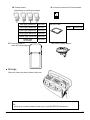
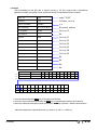
● Unpacking procedure
We thank you for purchasing our digital Power Meter KEW6305. Please check the contents and
instrument before us
e.
● Items listed below are included with the standard set:
1 Main unit KEW6305: 1 unit
2
Voltage test lead
MODEL7141B:1 set
(RED, GREEN, BLUE, BLACK: 1 pce
for each)
3 Power cord MODEL7170: 1 pce
4 USB cord MODEL7148: 1 pce
5 Quick manual 1 pce
6 CD-ROM 1 pce
7 Battery Alkaline size AA battery (LR6): 6pcs
8 SD Card 1 pce
9 Carrying case MODEL9125: 1 pce
Optional parts
10 Clamp sensor Depending on model purchased
11
Instruction manual for
Clamp sensor
1 pce
12 SD Card 2GB
13 Carrying case for Main unit MODEL9132
14 Power supply adapter MODEL8312
1. Main unit 2. Voltage test lead 3. Power cord 4. USB cord
5.
Quick 6.CD-ROM 7. Battery 8. SD Card 9. Carrying case
manual

KEW6305
2
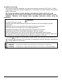
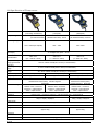
10. Clamp sensor 11. Instruction manual for Clamp sensor
(depending on model purchased)
50A type (Φ24mm) M-8128
12. SD Card
100A type (Φ24mm) M-8127
2GB M-8326-02
200A type (Φ40mm) M-8126
500A type (Φ40mm) M-8125
1000A type (Φ68mm) M-8124
3000A type
(Φ150mm)
M-8129
13. Carrying case for 14. Power supply adapter
main unit (with magnet)
● Storage
Store the items as shown below after use.
● In case any of the items listed above are found to be damaged or missing or if
the
printing is unclear, please contact your local KYORITSU distributor.

3 KEW6305
● Safety warnings
This instrument has been designed, manufactured and tested according to IEC 61010-1: Safety
requirements for Electronic Measuring apparatus, and delivered in the best condition after passing
quality control tests.
This instruction manual contains warnings and safety procedures which have to be
observed by the user to ensure safe operation of the instrument and to maintain it in safe
condition. Therefore, read through these operating instructions before using the
instrument.
WARNING
- For about Instruction manual -
● Read through and understand the instructions contained in this manual before using the
instrument.
● Keep the manual at hand to enable quick reference whenever necessary.
● The instrument is to be used only in its intended applications.
● Understand and follow all the safety instructions contained in the manual.
● Read the enclosed Quick manual after reading this instruction manual.
● As to the Clamp sensor use, refer to the instruction manual supplied with the sensor.
It is essential that the above instructions are adhered to. Failure to follow the above instructions
may cause injury, instrument damage and/or damage to equipment under test.
The symbol indicated on the instrument, means that the user must refer to the related parts in
the manual for safe operation of the instrument. It is essential to read the instructions wherever the
symbol appears in the manual.
DANGER : is reserved for conditions and actions that are likely to cause serious or fatal injury.
WARNING : is reserved for conditions and actions that can cause serious or fatal injury.
CAUTION
: is reserved for conditions and actions that can cause injury or instrument damage.

KEW6305
4
O Measurement Category
To ensure safe operation of measuring instruments, IEC 61010 establishes safety standards for
various electrical environments, categorized as O to CAT.IV, and called measurement categories.
Higher-numbered categories correspond to electrical environments with greater momentary
energy,
so a measuring instrument designed for CAT.III environments can endure greater momentary
energy
than one designed for CAT.II.
O : Circuits which are not directly connected to the mains power supply.
CAT.II : Electrical circuits of equipment connected to an AC electrical outlet by a power cord.
CAT.III : Primary electrical circuits of the equipment connected directly to the distribution panel,
and feeders from the distribution panel to outlets.
CAT.IV : The circuit from the service drop to the service entrance, and to the power meter and
primary overcurrent protection device (distribution panel).

5 KEW6305
DANGER
● Verify proper operation on a known source before use.
● Verify proper operation on a known source before taking action as a result of the indication of
the instrument.
● Never make measurement on a circuit in which the electrical potential exceeds 600VAC.
● Do not attempt to make measurement in the presence of flammable gasses. Otherwise, the use
of the instrument may cause sparking, which can lead to an explosion.
● Never attempt to use the instrument if its surface or your hand is wet.
- Measurement -
● Do not exceed the maximum allowable input of any measuring range.
● Never open the Battery cover during a measurement.
- Battery -
● Do not try to replace batteries during a measurement.
● Brand and type of the batteries to be used should be harmonized.
- Power cord -
● Connect the Power cord mains plug to a mains socket outlet.
● Use only the Power cord supplied with this instrument.
- Power supply connector -
● Never touch the Power supply connector although it is insulated while the instrument is
operating
with batteries.
- Voltage test leads -
● Use only the ones supplied with this instrument.
● Confirm that the measured voltage rating of the test lead is not exceeded.
● Do not connect a Voltage test lead unless required for measuring the parameters desired.
● Connect Voltage test leads to the instrument first, and only then connect them to the circuit
under
test.
● Never disconnect Voltage test leads while the instrument is in use.
● Connect to the downstream side of a circuit breaker since a current capacity at the upstream
side
is large.
● Do not touch two lines under test with the metal tips of the test leads.
● Never touch the metal tips of the test leads.
- Clamp sensor -
● Use only the ones dedicated for this instrument.
● Confirm that the measured current rating of the test lead is not exceeded.
● Do not connect a Camp sensor unless required for measuring the parameters desired.
● Connect sensors to the instrument first, and only then connect them to the circuit under test.
● Never disconnect sensors while the instrument is in use.
● Connect to the downstream side of a circuit breaker since a current capacity at the upstream
side
is large.
● Do not touch two lines under test with the metal tips of the test leads.

KEW6305
6
WARNING
- Connection -
● Confirm that the instrument is off, and then connect the Power cord.
● Connect the Power cord, Voltage test leads and Clamp sensors to the instrument first. Cord to
be firmly inserted.
● Never attempt to make any measurement if any abnormal conditions, such as a broken cover
or exposed metal parts are present on the Instrument, Voltage test leads, Power cord and
Clamp
sensor.
- Measurement –
● Ensure that the Current input terminal cover, USB connector cover and SD card connector cover
are closed when not in use during a measurement.
- Not in use for a long period -
● Remove the Power cord from the outlet if the instrument will not be in use for a long period.
- Repair/ Calibration -
● Do not install substitute parts or make any modification to the instrument. Return the instrument
to your local KYORITSU distributor for repair or re-calibration in case of suspected faulty
operation.
- Battery -
● Do not try to replace the batteries if the surface of the instrument is wet.
● Ensure that the Power cord, Voltage test leads and Clamp sensor are removed from the
instrument, and that the instrument is switched off when opening the Battery cover for battery
replacement.
● Never mix new and old batteries.
● Install batteries in correct polarity as marked inside the Battery compartment area.
- Power cord -
● Do not use the damaged cord.
● Don’t put heavy things on, step on or pinch the cord, moreover, not to touch any heating
material.
● When unplugging the cord from the mains socket outlet, do so by removing the plug first and not
by pulling the Power cord.
- Measures against abnormal symptoms -
● If the instrument begins to emit smoke, becomes too hot, or gives off an unusual smell,
immediately power it off and disconnect the power cord from the outlet. Also power off the power
to the object under test. If any anomalies as noted, contact your local KYORITSU distributor.
- Use of protective gears -
● Use insulated gloves, boots or head gears at measurements to ensure user’s safety.

7 KEW6305
CAUTION
● Caution should be taken since conductors under test may be hot.
● Never apply currents or voltages exceeding the maximum allowable input for the instrument for a
long time.
● Do not apply currents or voltages for the Voltage test leads or Clamp sensors while the instrument
is off.
● Don’t use the instrument at dusty places or to be spattered.
● Don’t use the instrument under a strong electric storm or in the vicinity of energized object.
● Never give strong vibrations or drop shocks.
● While using a SD card, do not replace or remove the card. ( symbol blinks while accessing
SD card.)
Otherwise, the saved data in the card may be lost or the instrument may be damaged.
- Clamp sensor -
● Do not bend or pull the cable of the Clamp sensor.
- Treatment after use -
● Power off the instrument and disconnect the Power cord, Voltage test leads and Clamp sensors
from the
instrument.
● Remove the batteries if the instrument is to be stored and will not be in use for a long period.
● Remove the SD card when carrying the instrument.
● Never give strong vibrations or drop shocks when carrying the instrument.
● Do not expose the instrument to direct sunlight, high temperatures, humidity or dew.
● Use a damp cloth with neutral detergent or water for cleaning the instrument. Do not use
abrasives or solvents.
● Do not store the instrument if it is wet.
Carefully read and follow the instructions: DANGER, WARNING, CAUTION and
NOTE ( )
described in each section.
The following symbols are used in this manual:
User must refer to the explanations in the instruction manual.
Instrument with double or reinforced insulation
AC
(Functional) Earth terminal
~

KEW6305
8

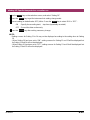
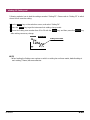
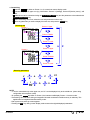
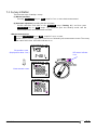
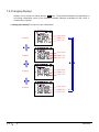
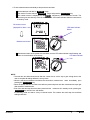
1.1 KEW6305
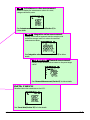
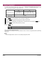
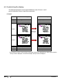
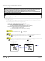
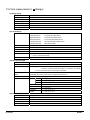
1. Instrument Overview
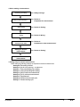
1.1 Functional Overview
SET UP
Make settings for KEW6305 or for
measurements.
See “Setting (Section 4)” for further details.
WIRING CHEC
K
Check the connections and display the
results.
See “Wiring check (Section 10)” for further
details.

KEW6305
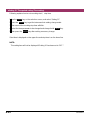
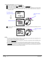
1.2
_
W
_
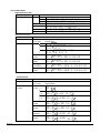
Instantane
o
us value measurement
Measure/ display the instantaneous values of current,
voltage and electric power.
See “Instantaneous value Measurement (Section 6)” for
further details.
_
Wh
_
Integration value me
a
surement
Display/ record active/ apparent/ reactive energies, and
record the average/ max/ min values of measured
instantaneous values.
See “Integration value Measurement (Section 7)” for further
details.
_
DEMAND
_
Demand measurement
Display/ record demand values based on the preset target
values.
See “Demand Measurement (Section 8)” for further details.
DATA CHEC
K
Recall and show the saved data on the LCD.
See “Saved data (Section 10)” for further details.

1.3 KEW6305
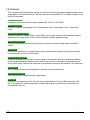
1.2 Features
This is a digital Power Clamp Meter that can be used for various wiring systems. Measured data can be
saved either in the internal memory or SD card, and can be transmitted to PC via USB connection or by
using SD card reader.
Safety Construction
Designed to meet the international safety standard IEC 61010-1 CAT.III 600V.
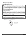
Wiring configuration
KEW6305 supports: Single-phase 2-wire, Single-phase 3-wire, Three-phase 3-wire, Three-phase
4-wire.
Measurement and calculation
KEW6305 measures voltage (RMS), current (RMS), active power, frequency and calculates reactive/
apparent power, power factor, neutral current and active/ reactive/ apparent energy.
Demand measurement
Electricity consumption can be easily monitored so as not to exceed the target maximum demand
values.
Saving data
KEW6305 is endowed with a logging function with a preset recording interval. Data can be saved by
manual operation or at pre-set time & date.
Dual power supply system
KEW6305 operates either with an AC power supply or with batteries. Both dry-cell batteries (alkaline)
and rechargeable batteries (Ni-MH) can be used. In the event of an interruption, while operating with
an AC power supply, power to the instrument is automatically restored by the batteries in the instrument.
Large display
Up to 3 measured items can be displayed on the large screen simultaneously.
Light & compact design
Clamp sensor type, compact and light weight design
Application
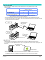
Data in the internal memory and in SD card can be transmitted to PC using USB connection or SD
slot. The supplied PC software application enables easy settings of the instrument and analysis of
the saved data from PC.

KEW6305
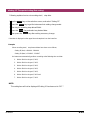
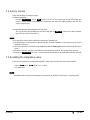
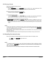
1.4
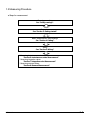
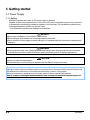
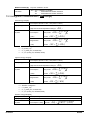
1.3 Measuring Procedure
● Steps for measurement
Ensuring your safety
See “Safety warnings”.
Preparation
See “Section 3: Getting started”.
Basic / Measurement / Save Settings
See “Section 4: Setting”.
Wiring
See “Section 5: Wiring”.
* Measuring instantaneous values :
“Section 6: Instantaneous value Measurement”
* Measuring integration values:
“Section 7: Integration value Measurement”
* Measuring demand values:
“Section 8: Demand Measurement”

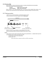
1.5 KEW6305
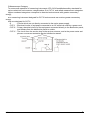
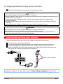
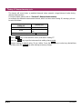
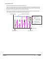
1.4 Outline of max demand measurement concept
In some countries, large consumers of electricity will usually have a maximum demand contract with
the power company. Such contract varies from country to country. The following is an explanation of
a typical Japanese maximum demand contract.
● Maximum Demand contract
In such a contract the electricity tariff rates (i.e. for kWhr units) are based upon the consumer’s
maximum power demand. The maximum demand is the maximum of average powers recorded
over a 30min intervals.
This is measured by the maximum demand meter belonging to the power company. Let’s assume
that a power company has the following applicable rates.
$2 per KWhr unit for a recorded max demand 300KW during a year
$4 per KWhr unit for a recorded max demand 500KW during a year
$5 per KWhr unit for a recorded max demand 600KW during a year
Assuming that the consumer is on the 500kW/year rate (ie. $4), and the recorded max demand
during a particular day(say 15th January) is 600kW . Then the new applicable rate from 1st
February onwards will be the 600kW/year rate (ie. $5) for the next 365 days. If a year later, on
February 1st the recorded maximum demand is 300kW, then the new applicable rates will be
changed to 300kW/year rate (i.e. $2) for the subsequent 365 days. However if during this period,
the max demand goes up again, and say 600kW is recorded on 15th March, the applicable rates
change again to the 600kW/year rate (i.e.$5) for the subsequent 365 days.
● Benefits of maximum demand control
It is thus important for consumers with such contracts to monitor closely fluctuations in their power
demand to ensure that their max demand limits are not exceeded and thus incur higher tariffs.
Maximum Demand control is more effective in countries with higher electricity tariffs.
● Status of maximum demand contract
In the past, in Japan, only consumers whose electricity supply was rated at 600kW or more used to
enter into a demand contract. However, nowadays power companies install maximum demand
meters at all consumers whose supply is rated 70kW or more.
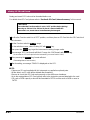
● Maximum Demand measurement limitations
N.B. The readings from power company maximum demand meter and from the 6300 will not match
completely due to an obvious time-lag difference in the start of the integration period (eg.30mins)
over which the max demand is taken.

KEW6305
1.6

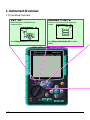
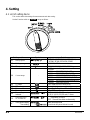
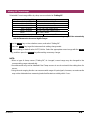
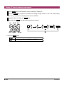
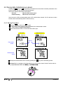
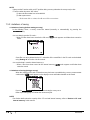
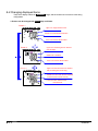
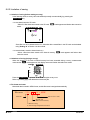
2.1 KEW6305
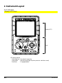
Display (LCD)
Keys
LED status indicator
Green lights up : Recording & measuring
Green blinks : Stand-by mode (lights up when preset rec. start time comes)
Red blinks : Charging batteries
2. Instrument Layout
2.1 Front view
Display (LCD) / Keys

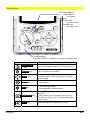
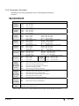
KEW6305 2.2
Function switch:
Power on KEW6305. (Rotate to any position other than “OFF”.)
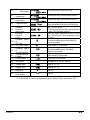
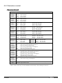
Key functions
Keys Details
START/STOP
Key
Start/ stop integration and demand measurement.
Backlight Key Turn on/ off the LCD backlight.
Cursor Key
On measurement screen: switch screens, and
on setting screen: select setting items or change
values or digits
ENTER Key Confirm entries.
ESC Key
* Cancel setting changes,
* Clear integration / demand values.
DATA HOLD Key
* Data hold
* Key lock
A long press (2 sec or longer) locks Keys and
another long press (2 sec or longer) unlocks the
locked Keys.
SAVE Key Save the measured instantaneous values.
LED status indicator
Green lights up :
Recording &
measuring
Green blinks :
Stand-by mode
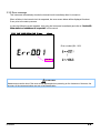
Red lights up :
Recording error

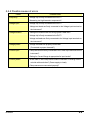
2.3 KEW6305
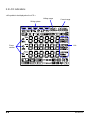
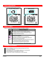
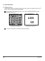
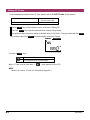
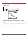
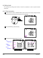
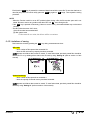
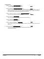
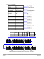
2.2 LCD indications
< All symbols to be displayed on the LCD >
Unit
Phase
number
Wiring system
Current range
Voltage range

KEW6305 2.4
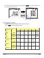
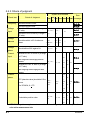
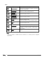
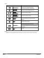
< Symbols indicate the functions or status during measurement >
Symbols Functions and status during measurement
Lights up when the keys are locked.
Lights up when voltage exceeds a certain condition.
Lights up when current exceeds a certain condition.
Lights up when instruments is working by AC power supply.
Lights up when instruments is working by batteries.
Lights up when data hold function is activated.
Lights up when selecting SET UP Range.
Lights up when selecting WIRING CHECK Range.
Blinks while instantaneous values are being displayed on the LCD.
Blinks while integration values are being displayed on the LCD.
Blinks while demand values are being displayed on the LCD.
When the capacity of SD card or internal memory is exceeded.
Lights up when selecting DATA CHECK Range.
Lights up while data can be saved in the SD card, and blinks while
saving data.
Lights up while a USB cord is connected to the terminal, and blinks
during data communication.
Lights up while using Bluetooth communication.
Lights up while data can be saved in the internal memory, and blinks
while accessing to the memory.
Lights up when VT ratio is set to other than “1”.
Lights up when CT ratio is set to other than “1”.

2.5 KEW6305
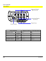
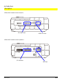
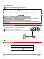
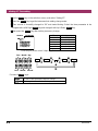
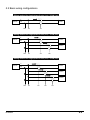
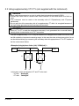
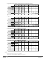
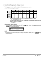
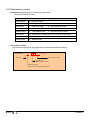
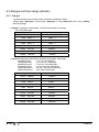
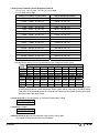
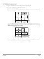
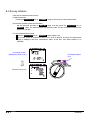
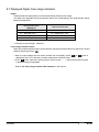
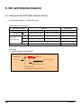
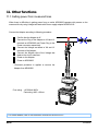
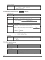
2.3 Connector
Descriptions
Wiring configuration Voltage Input Terminal Current Input Terminal
Single-phase 2-wire
1P2W(1ch)
VN, 1 A1
Single-phase 2-wire (2ch)
1P2W(2ch)
VN, 1 A1, 2
Single-phase 2-wire (3ch)
1P2W(3ch)
VN, 1 A1, 2, 3
Single-phase 3-wire
1P3W
VN, 1, 2 A1, 2
Three-phase 3-wire
3P3W
VN, 1, 2 A1, 2
Three-phase 3-wire 3A
3P3W3A
V1, 2, 3 A1, 2, 3
Three-phase 4-wire
3P4W
VN, 1, 2, 3 A1, 2, 3
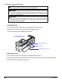
Voltage Input Terminal
(VN, V1, V2, V3)
Power Connector
Current Input Terminal
(A1, A2, A3,)
Terminal Cover
Page is loading ...
Page is loading ...
Page is loading ...
Page is loading ...
Page is loading ...
Page is loading ...
Page is loading ...
Page is loading ...
Page is loading ...
Page is loading ...
Page is loading ...
Page is loading ...
Page is loading ...
Page is loading ...
Page is loading ...
Page is loading ...
Page is loading ...
Page is loading ...
Page is loading ...
Page is loading ...
Page is loading ...
Page is loading ...
Page is loading ...
Page is loading ...
Page is loading ...
Page is loading ...
Page is loading ...
Page is loading ...
Page is loading ...
Page is loading ...
Page is loading ...
Page is loading ...
Page is loading ...
Page is loading ...
Page is loading ...
Page is loading ...
Page is loading ...
Page is loading ...
Page is loading ...
Page is loading ...
Page is loading ...
Page is loading ...
Page is loading ...
Page is loading ...
Page is loading ...
Page is loading ...
Page is loading ...
Page is loading ...
Page is loading ...
Page is loading ...
Page is loading ...
Page is loading ...
Page is loading ...
Page is loading ...
Page is loading ...
Page is loading ...
Page is loading ...
Page is loading ...
Page is loading ...
Page is loading ...
Page is loading ...
Page is loading ...
Page is loading ...
Page is loading ...
Page is loading ...
Page is loading ...
Page is loading ...
Page is loading ...
Page is loading ...
Page is loading ...
Page is loading ...
Page is loading ...
Page is loading ...
Page is loading ...
Page is loading ...
Page is loading ...
Page is loading ...
Page is loading ...
Page is loading ...
Page is loading ...
Page is loading ...
Page is loading ...
Page is loading ...
Page is loading ...
Page is loading ...
Page is loading ...
Page is loading ...
Page is loading ...
Page is loading ...
Page is loading ...
Page is loading ...
Page is loading ...
Page is loading ...
Page is loading ...
Page is loading ...
Page is loading ...
Page is loading ...
Page is loading ...
Page is loading ...
Page is loading ...
Page is loading ...
Page is loading ...
Page is loading ...
Page is loading ...
Page is loading ...
Page is loading ...
Page is loading ...
Page is loading ...
Page is loading ...
Page is loading ...
Page is loading ...
Page is loading ...
Page is loading ...
Page is loading ...
Page is loading ...
Page is loading ...
Page is loading ...
Page is loading ...
-
 1
1
-
 2
2
-
 3
3
-
 4
4
-
 5
5
-
 6
6
-
 7
7
-
 8
8
-
 9
9
-
 10
10
-
 11
11
-
 12
12
-
 13
13
-
 14
14
-
 15
15
-
 16
16
-
 17
17
-
 18
18
-
 19
19
-
 20
20
-
 21
21
-
 22
22
-
 23
23
-
 24
24
-
 25
25
-
 26
26
-
 27
27
-
 28
28
-
 29
29
-
 30
30
-
 31
31
-
 32
32
-
 33
33
-
 34
34
-
 35
35
-
 36
36
-
 37
37
-
 38
38
-
 39
39
-
 40
40
-
 41
41
-
 42
42
-
 43
43
-
 44
44
-
 45
45
-
 46
46
-
 47
47
-
 48
48
-
 49
49
-
 50
50
-
 51
51
-
 52
52
-
 53
53
-
 54
54
-
 55
55
-
 56
56
-
 57
57
-
 58
58
-
 59
59
-
 60
60
-
 61
61
-
 62
62
-
 63
63
-
 64
64
-
 65
65
-
 66
66
-
 67
67
-
 68
68
-
 69
69
-
 70
70
-
 71
71
-
 72
72
-
 73
73
-
 74
74
-
 75
75
-
 76
76
-
 77
77
-
 78
78
-
 79
79
-
 80
80
-
 81
81
-
 82
82
-
 83
83
-
 84
84
-
 85
85
-
 86
86
-
 87
87
-
 88
88
-
 89
89
-
 90
90
-
 91
91
-
 92
92
-
 93
93
-
 94
94
-
 95
95
-
 96
96
-
 97
97
-
 98
98
-
 99
99
-
 100
100
-
 101
101
-
 102
102
-
 103
103
-
 104
104
-
 105
105
-
 106
106
-
 107
107
-
 108
108
-
 109
109
-
 110
110
-
 111
111
-
 112
112
-
 113
113
-
 114
114
-
 115
115
-
 116
116
-
 117
117
-
 118
118
-
 119
119
-
 120
120
-
 121
121
-
 122
122
-
 123
123
-
 124
124
-
 125
125
-
 126
126
-
 127
127
-
 128
128
-
 129
129
-
 130
130
-
 131
131
-
 132
132
-
 133
133
-
 134
134
-
 135
135
-
 136
136
-
 137
137
-
 138
138


KYORITSU KEW 6305 User manual
- Category
- Measuring, testing & control
- Type
- User manual
Ask a question and I''ll find the answer in the document
Finding information in a document is now easier with AI
Related papers
-
KYORITSU KEW8140 Series Leakage Clamp Sensor User manual
-
-
-
-
KYORITSU 3551 Owner's manual
-
KYORITSU KEW SNAP 2432 User manual
-
KYORITSU 1110 User manual
-
-
Other documents
-
 Sperry instruments 6300 Owner's manual
-
 Entes MPR-26S-21-PM User manual
-
Mastech MS8360G User manual
-
 Uni-Trend UT232 Specification
-
T&D TR-77Ui User manual
-
Klein Tools CL150 Installation guide
-
 Aichi Tokei Denki NH***-4 Series User manual
-
UNI-T UT231 Specification
-
Anritsu HD-1500 Series User manual
-
Amprobe DM-5 User manual


