Page is loading ...

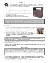
Propane CO2 Generator
LP5 / LP10
Repair & Maintenance
Guide
Version 1.2
May 2012

LP5 / LP10 Maintenance Guide Version 1.2
2
CONTENT
SECTION
TITLE
PAGE
A
IMPORTANT WARNINGS
2
B
Tool Kit and Replacement Parts
2
C
Illustrated Glossary
3
D
Lifting and collapsing the enclosure top part (flame shield)
4
E
Troubleshooting steps and contact information
5
F
Basic functional Test WITHOUT gas
6
G
Basic functional Test WITH gas
7
H
Connecting the hose / regulator assembly
9
I
Bleeding the gas line
10
J
Replacing a fuse
11
K
Cleaning the burners orifices and slotted caps
12
L
Removing the enclosure top part (flame shield) for maintenance
14
M
Closing the enclosure top part (flame shield) after maintenance
15
A- IMPORTANT WARNINGS
Unit works with PROPANE ONLY. Connectors and fittings will not connect to
NATURAL GAS line.
RAISE the FLAME SHIELD before using the burner, see Section D
It is NOT SAFE to use the generator WITHOUT the FLAME SHIELD. However, it is
possible to use the burner without the shield for maintenance purpose, in a SAFE
AND VENTILATED LOCATION. In this case, use the generator away from
combustible or explosive material.
B- TOOL KIT AND REPLACEMENT PARTS
TOOL KIT
# Ref.
Qty
Tool
1
1
0.020 Orifice Cleaning Drill
2
1 tube
White Grease “Gimme the White Stuff”
3
1
Burner and Cap Cleaning Brush
4
1
1/2 inch Key to screw/unscrew slotted cap burner on manifold
5
1
3/4 inch Key to screw/unscrew hose on gas intake
6
1
Robertson (Square or socket head) Screwdriver (#2 or Red)
7
1 roll
Teflon Tape Roll
REPLACEMENT PARTS
# Ref.
Qty
Tool
A
10
3000 BTU/hr Slotted Cap Burner
B
12
Rubber Feet
C
2
10-ft Hose / Regulator Assembly
D
10
1A SLOW BLOW Fuse (do not use Fast Blow Type)

LP5 / LP10 Maintenance Guide Version 1.2
3
C- ILLUSTRATED GLOSSARY
The FLAME SHIELD is made from the enclosure's BLACK PARTS.
The Flame Shield can be raised or collapsed over the
REPLACEABLE BASE. Bases are available separately. They are
made from the enclosure's GREY part, where the electrical and gas
components are mounted.
PILOT ASSEMBLY: mounted next to the
manifold inside.
GP – Glow Plug
TS – Temperature Sensor (Rod Shape)
GFG – Gas Flow Guide
---------------------------------------------------
MANIFOLD / BURNER ASSEMBLY:
MF – Manifold (Single LP5, Dual LP10)
SCB – Slotted Cap Burners (5 or 10)
TS: the sensor is a thermo-
electrical device: once
heated by the pilot flame, it
allows the main valve to let
gas flow through the
manifold/ /burner assembly.
GP: do not bend, it is made of ceramic-like
metal that breaks easily (not covered by
warranty). Glow Plug will turn red and hot
in attempt to ignite the pilot flame.
HONEYWELL SMART VALVE::
PC – Pilot Connector and Wiring (Blue)
PS – Power Switch, must be ON
PSC – Power Supply Connector
PS
PC
PSC
The POWER CORD
and FUSE HOLDER
are located on this side
of the unit.
The GAZ CONNECTOR
is located on this opposite
side of the unit.
GFG: gas will be guided
toward the Glow Plug to
ignite.
SCB: gas flows from the
tiny orifice at the bottom
and up to the slotted cap at
top. Caps are removable.
MF: gas is fed to the
manifold (round tubing)
before flowing through the
5 burners per manifold.

LP5 / LP10 Maintenance Guide Version 1.2
4
D- LIFTING AND COLLAPSING THE ENCLOSURE TOP PART (FLAME
SHIELD)
Step #
Description
Photos or comments
1
Before RAISING: the 4 Wing Screws (2 on each side) must be
loosened (from tight position) about 4 to 5 half-turns.
2
Before RAISING: holding the flame shield in open (up) position, the
wing screw should fit into the L-Notch at the bottom of the SLIDE
SLOTS.
In this example, a wing screw has been unscrewed many turns to
show the L-Notch at the bottom of the slide slot.
Slide L-Notch
3
To RAISE and HOLD the Flame Shield in OPEN POSITION:
Unscrew wing nuts 4 to 5 half turns
Lift the cover placing your hands inside the openings on the
top sides of unit. Wing screws will be guided to the bottom of
the slide slots while lifting the part.
Once lifted, twist the whole shield clockwise to lock the 4
wing screws into the Slide L-Notch.
Tighten the 4 wing screws by hand (no tool required).
4
To COLLAPSE and HOLD the Flame Shield in CLOSE POSITION:
Unscrew wing nuts 4 to 5 half turns
Place your hands inside openings towards the top of the unit.
Twist the whole shield counter clockwise to take the 4 wing
screws out of the Slide L-Notch.
Lower the cover. The wing screws will be guided towards the
top of the slide slots.
Once fully collapsed, tighten the 4 wing screws by hand (no
tool required).
5
Once the wing screws are tightened, you can manipulate the unit using
the large opening on top.

LP5 / LP10 Maintenance Guide Version 1.2
5
E- TROUBLESHOOTING STEPS AND CONTACT INFORMATION
Step #
Description
1
Basic Functional Test WITHOUT gas (Section F)
2
Basic Functional Test WITH gas (Section G)
NOTE:
Repair Tips and Suggestions are provided while performing the tests. If problems persist, the base
may need to be replace: in this case refer to Sections L and M.
CONTACT:
All email inquiries can be sent to service@grozonecontrol.com or by phone at 418-308-0940
/ 1-855-262-1800 Monday to Friday, 8am to 5pm EST

LP5 / LP10 Maintenance Guide Version 1.2
6
F- Basic Functional Test WITHOUT gas
Step #
Description
Photos or comments
1
Raise top part of FLAME SHIELD to check up the
Pilot Glow Plug through one of the large openings on
the top.
2
Connect the Power Cord into 120V outlet. After 3-4
seconds, a clicking sound will indicate that the
PILOT VALVE and GLOW PLUG have been
activated.
3
Verifying the Pilot Glow Plug: the PILOTE VALVE
and GLOW PLUG turn red and become hot after only
a few second once they are activated.
If successful, it means the fuse is good and the whole
unit is likely to work properly when connected to the
gas tank.
4
If this test fails:
4a
Verifying the fuse : see Section J
4b
Verifying the Valve ON/OFF Switch : see the Power
Switch in Definition of Terms. The Switch must be
ON at all times.
ON Position is RIGHT
4c
Verifying the Pilot Wiring : blue wires run from the
Valve to the Pilot Assembly, mounted next to the 5-
burner or 10-burner manifold. The Insulation may
have melted causing the copper to touch, creating a
short circuit. In this case, the fuse is likely to blow
up each time the power cord is connected! If pilot
needs to be changed: change replaceable Base.

LP5 / LP10 Maintenance Guide Version 1.2
7
G- Basic functional Test WITH gas
Step #
Description
Photos or comments
1
Raise the FLAME Shield top part. Note: using the
generator with the flame shield in collapsed position is
UNSAFE.
2
Connect the Hose / Regulator Assembly into the gas
intake fitting. See Section H
3
Screw in the Regulator Quick Connect into the Tank
connector. OPEN the tank valve.
4
Connect Power cord in 120V outlet.
Has the gas line been bleeded (purged from air) ?? If
not See Section I.
5
Verifying the Pilot Glow Plug: the PILOTE VALVE
and GLOW PLUG turn red and become hot after only
a few second once they are activated.
6
The gas flowing on the Glow Plug should ignite.
THEN the Temperature Sensor (bent rod) will turn red
and send a thermo-electric signal to the smart valve, it
will then activate its MAIN GAS VALVE to let gas
flow through the manifold(s).
The first burner next to the pilot will ignite quickly.
If burners does not lit up, unplug the power cord and
return to Step 4. If ONLY the pilot ignites, the VALVE
may be damaged. The base needs to be changed.
7
In normal AIR CIRCULATION conditions, the other
burners will ignite in just seconds. It may be longer
when using the unit for the first time (the manifold
need to fill up with propane before flowing through the
burners).

LP5 / LP10 Maintenance Guide Version 1.2
8
8
The other burners will ignite quickly once the first
burner is lit. It may take up to 10 seconds for the
burners located at the ends of the manifold to turn on.
It is normal and is not dangerous.
At the next power up, all burners should lit in just
seconds.
One burner among 5 or 10 is not lighting up ? Soot or
dirt may obstruct the burner's tiny orifice. See section
K.
9
Flames are BLUE when burning condition and valve
setting have been optimized. BLUE flames means
GOOD COMBUSTION, generating CO2 and WATER
VAPOR (causing humidity in the room), and VERY
FEW CO (Dangerous Carbon Monoxide).
ORANGE flames are observed when a lot of air
circulates across the unit (room fan being too close to
the unit).
It is normal to observe ORANGE flames around the
pilot near the center of the manifold)
When flames are mainly ORANGE, you may need to
clean up the burners: see Section K.
Air quality in your environment is also likely to
influence the flame color.
If the flames are “dancing” (going up and down every
2-3 seconds), the gas tank pressure or level is probably
too low: fill up the tank with propane.

LP5 / LP10 Maintenance Guide Version 1.2
9
H- CONNECTING THE HOSE / REGULATOR ASSEMBLY
Step #
Description
Photos or comments
1
In order to prevent gas leaks, it is good practice to add a 2-inch
Teflon tape to the gas intake fitting before connecting the
hose.
2
Place the Teflon tape CLOCKWISE around the MALE fitting.
Stretch and apply the tape once or twice around the fitting.
3
Tighten the hose female connector by hand then complete
with 1/8 turn using a 3/4 inch key. DO NOT apply excessive
strength, assure a tight connection.
SOAP WATER SOLUTION can be used to check gas leak.
Bubbles are formed where gas is leaking.

LP5 / LP10 Maintenance Guide Version 1.2
10
I- BLEEDING THE GAS LINE
Step #
Description
Photos or comments
1
When connecting the Hose and Tank to the Generator
for the first time, bleeding the gas line may be
required.
BLEEDING the line means purging the air in the hose
and filling it up with enough propane to maintain gas
combustion once the unit is ignited.
2
After connecting the hose / regulator assembly to the
tank, plug the power cord: the Glow Plug will turn
RED with NO gas ignition.
Wait about 30 seconds until the Glow Plug turns OFF
automatically (the Smart valve does it for safety
purpose, when no ignition has occurred after a delay).
Then, unplug the power cord again and connect it
back right away. The Pilot will go through a new 30-
seconds ignition cycle.
It may take up to 2or 3 cycles to bleed the line, before
the pilot finally ignites.
If it take more than 3 cycles to bleed the line, check the
tank valve level or pressure.

LP5 / LP10 Maintenance Guide Version 1.2
11
J- REPLACING A FUSE
Step #
Description
Photos or comments
1
The Fuse Holder is located next to the power cord strain relief.
Unscrew Fuse Holder CAP.
2
Pull CAP from holder.
3
Remove fuse from CAP and place a new fuse. Fuse has no polarity: any end
can be placed in the Holder CAP.
Verifying that the fuse is good: the tiny filament inside the glass
compartment shall not be melted or cut !

LP5 / LP10 Maintenance Guide Version 1.2
12
K- CLEANING THE BURNERS ORIFICES AND SLOTTED CAP
Step #
Description
Photos or comments
1
The burners slotted cap will cumulate soot, dirt and carbon burning
residues with time. Such residues will degrade the combustion
quality and is likely to generate ORANGE flames (less CO2, more
CO).
Cleaning a burner requires 2 steps:
Cleaning the SLOTTED CAP
Cleaning the BODY
DIRT in Slotted Cap
2
Cleaning the SLOTTED CAP:
Caps must be removed to clean. Unscrew by hand or with a tool :
avoid using excessive strength that could distort the part.
2b
Use the metal brush included in the tool kit to remove dirt from cap
slots.
3
If dirt is present at the bottom of the burner's body, blow the dirt
away (with or without an air compressor) from TOP or BOTTOM
SIDE HOLES.
SIDE HOLES are important for combustion quality and need to be
free of dirt at all times.
If the dirt cannot be removed, REMOVE THE BURNER FROM
THE MANIFOLD USING THE ½ INCH KEY.

LP5 / LP10 Maintenance Guide Version 1.2
13
4
Shake the burner head down (thread up) to remove dirt or
combustion residues (carbon particles).
5
If necessary, use the HAND DRILL.
Warning: this tool is VERY fragile, any strength applied laterally
will break the drill (1/50 inch diameter): keep the drill parallel to the
hole direction.
Dirt is normally easy to drill out.
5b
6
IMPORTANT NOTICE :
USE OF WHITE GREASE (GAS SEALANT)
If a burner needs to be replaced, use WHITE GREASE (see white
tube in tool kit) around the MANIFOLD HOLE THREAD before
screwing the new burner into place.
Using too much grease (sealant) may obstruct the burner orifice.
DO NOT use excessive strength when screwing the burner back into
place. Use ½ inch key.

LP5 / LP10 Maintenance Guide Version 1.2
14
L- REMOVING THE ENCLOSURE TOP PART (FLAME SHIELD) FOR
MAINTENANCE
Step #
Description
Photos or comments
1
Use the Robertson Screwdriver (#2, Red, Square or Socket head) to remove
the 4 screws on both sides of the units. The FLAME SHIELD can now be
removed.
2
Place both hands into the openings on top sides of enclosure. Lift the
FLAME SHILED evenly.
3
Once removed all gas and electrical components are accessible. Gas hose
doesn’t need to be disconnected before removing the flame shield.
IMPORTANT WARNING:
It is NOT SAFE to use the generator WITHOUT the
FLAME SHIELD. However, it is possible to use the
burner without the shield for maintenance purpose,
in a SAFE AND VENTILATED LOCATION. In this
case, use the generator away from combustible or
explosive material.

LP5 / LP10 Maintenance Guide Version 1.2
15
M- CLOSING THE ENCLOSURE TOP PART (FLAME SHIELD) AFTER
MAINTENANCE
Step #
Description
Photos or comments
1
Valve wiring (blue wires to pilot, red wires to transformer) may need to be
pushed back inside the enclosure to avoid stripping them off while sliding
the flame shield back into place.
1a
2
Keep each BASE LIP inside the flame shield. Base have two right angle
LIPS, one at the front, one at the back.
BASE LIP
3
TIP: Lifting the flame shield slightly may be needed (with a flat
screwdriver) to align the 4 screws holes on flame shield with the 4 threaded
holes on base.
End of document
/