Page is loading ...

ares
™
4 Burner Series LP/NG
Instruction Manual
www.titancontrols.net
®
VANCOUVER, WASHINGTON U.S.A.
1 Square = ____ Foot/Feet
www.titancontrols.net
VANCOUVER, WASHINGTON U.S.A.
Revision HG – 1/21/2013 © Titan Controls®

112
Ares™ Series - 4 Burner
• Warnings
• Ares™ Series - CO
2
Generator Overview
• Installation
• Start Up Procedure
• Troubleshooting Notes
• What to do if you smell gas?
• CO
2
Generator Specications
• Warranty Information
• Service and Repair Program
Warnings
• Read all instructions before operating your Ares™ Series – CO
2
Generator
• Do not put your CO
2
generator in an area where it can get wet or sprayed
• Mount your CO
2
generator SECURELY to the ceiling using hardware provided
• LP/NG gases can be dangerous – check all connections with soapy water before ring
• If you smell gas, unplug CO
2
generator and do NOT re-light until connections are tightened
• When using “bug bombs” in area, cover CO
2
generator completely to avoid corrosion
• There are no serviceable parts in CO
2
generator. Do not attempt to repair the unit
• Breaking “warranty” seal will void your warranty
• When CO
2
generator is NOT in use, place in sealed bag (i.e. garbage bag, etc)
• Do not put paper clips, tools, etc. into unit. Possible electrocution may occur
• Make sure to verify your power source prior to plugging CO
2
generator into outlet
• Check that all equipment that will activate this CO
2
generator is the proper voltage
• Avoid touching or handling CO
2
generator chassis while operating. You may get burned
• Use caution when operating CO
2
generator in extremely humid environments
• Operate CO
2
generator in well ventilated area
• Do NOT use Teon tape on gas connections. All gas ttings are self sealing
• Do not use CO
2
generator for purposes other than the unit was designed to function
• Use CO
2
generator within dened environmental specications
• Ask your Dealer for tips and techniques regarding the use of this CO
2
generator
• Be conscientious when disposing of any products
Include the following if returning directly to Titan Controls
®
• Proof of purchase • This completed form • RMA # on the outside of the box
Return Merchandise Authorization Number (Required
Company Name: ____________________________________________________________________________________
Contact Name: _____________________________________________________________________________________
Address: __________________________________________________________________________________________
____________________________________________________________________________________________________
Phone #: ___________________________________________________________________________________________
Email address: _______________________________________________________________________________
What is the nature of the problem?
______________________________________
___________________________________________________________
___________________________________________________________
___________________________________________________________
___________________________________________________________
___________________________________________________________
Shipping address will be given when the RMA # is issued.
www.titancontrols.net
For technical assistance call us at 1-888-80-Titan or 1-888-808-4826.
®
FOR WARRANTY SERVICE: Please read warranty information first.
If after reviewing the troubleshooting tips the unit will still not work, you should return it to the
Dealer where you purchased the controller. They will be able to further evaluate the unit and
test its various components and quite possibly will be able to identify and/or x any problems.
If the Dealer is unable to x the unit, they will return it to us for factory repair.
If there are no Dealers in your area, you may contact us directly for technical support. If we
can¬not help you resolve the problem over the phone, we will issue you a RMA # (return
merchandise¬authorization) authorizing you to return the unit to us for factory reconditioning
(if the unit is under warranty). Contact the number below for a RMA and shipping address.
Complete the form below and include it with your unit. Also please write the RMA # on the
outside of the box.
Please package the unit in its original packaging. If it is damaged in shipment we cannot be
responsible.
Once we receive the unit back, we will repair the controller within 48 hours (business) and
return it to you freight prepaid via UPS ground shipment.

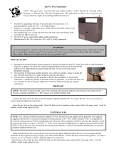
Ares™ Series – CO
2
Generator Overview
The Ares™ Series – CO
2
Generator is used to create and maintain the CO
2
in your growing
environment. CO
2
has been proven to considerably increase the growth of plants. The
normal level of CO
2
in the environment is between 300 parts per million (ppm) to 600 ppm.
The recommended level of CO
2
in the grow area should be between 1000 ppm and 1500
ppm. Your plants uptake CO
2
only during day light hours, so by utilizing a CO
2
controller
(Atlas
®
Series CO
2
Monitor/ Controller) or short cycle timer (Apollo™ Series timer) or a multi-
functional controller (Kronus
®
Series Environmental controller) will allow you to effectively
monitor and dose CO
2
in a safe and efcient method. The Ares™ Series – CO
2
Generator
is easy to set up and operate (See Installation Examples). Products created for our
industry, by our industry. Ares™ Series – CO
2
Generators are built with the highest quality
components to provide the operator with years of trouble free service.
Installation
Determine the best location for the generator. It must be hung level, in an open area that is
adequately ventilated.
WARNING: In spaces without proper ventilation CO
2
levels can accumulate and become
toxic (levels above 5,000 PPM). Plants benet from levels up to 1,500 PPM. Levels above
2,500 PPM can cause headaches and/or feelings of being ill.
The generator requires on unrestricted ow of air through the bottom and must be hung.
Select an overhead support, such as a ceiling joist, to hang the generator. The unit must
have a minimum clearance of 20” of space between it and any other obstructions. Use the
included hardware (20” chain, screw hook, and carabiners) to securely hang the generator.
1. Install the screw hook into the overhead support. Use the carabiners to secure the chain
to the unit and the screw hook.
2. Verify that the generator is hanging level. The generator has a safety feature (the tip over
switch) that will turn off the burners if the unit tips over or falls down. The switch is like a
pendulum and will turn off the unit if it is not level.
3. Verify that the gas supply and the regulator being used match the type of CO
2
generator
you’re using (LP or NG).
4. Securely tighten the gas connection with 2 wrenches using the included gas supply
hose. Connect one end to the are tting and the other end to the provided gas regulator.
Verify the connection is secured safe.
5. Pressurize the gas line after connections are veried. Use soapy water and a spray bottle
to check for leaks by spraying it onto the gas connection ttings and watch for bubbles. If
bubbles appear, re-secure the connection and repeat the process.
6. Using the included power supply, connect the unit to a controller or timer that will
determine the amount of time and how frequently the generator will operate.
Note: This generator requires 120 VAC to 24VDC power. Use only power supply included
with the CO
2
generator.
7. The ignition module and ring sequence are activated by the main power switch located
on the side of the generator. The generator has power and is in operation if the green
‘Power On’ indicator light is on.
Notes:
________________________________________________
________________________________________________
________________________________________________
________________________________________________
________________________________________________
________________________________________________
________________________________________________
________________________________________________
________________________________________________
________________________________________________
________________________________________________
________________________________________________
_______________________________________________
________________________________________________
________________________________________________
________________________________________________
________________________________________________
________________________________________________
________________________________________________
________________________________________________
________________________________________________
________________________________________________
_______________________________________________
________________________________________________
________________________________________________
________________________________________________
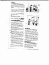
310

Atlas® series or
Apollo
™ series
Atlas
® series or
Apollo
™ series
To natural
gas source
CO
2
Generator using LP Tank
CO
2
Generator Using NG Supply Line
Atlas® series or
Apollo
™ series
Atlas
® series or
Apollo
™ series
To natural
gas source
Note: DO NOT TURN ON THE GENERATOR. After the unit has been successfully installed,
read the ‘Start-Up Procedure’ to ensure safe and proper use of the generator.
WARNING: A spark is produced from a pair of electrodes near the tip of the brass burners
to ignite the gas. Keep foreign objects away from the electrodes.
Warranty Information
Titan Controls
®
warrants the original purchase of this product against defects in material
and workmanship under normal use for three (3) years from the date of purchase.
• During the warranty period, Titan Controls
®
will, at our option, and without charge, repair
or replace this product if the controller or any of its components fail or malfunction.
• All returns or repairs must be accompanied by a Return Merchandise Authorization (RMA)
number prior to any service of the product.
• This warranty is expressly in lieu of all other warranties, expressed or implied, including
the warranties of merchantability and tness for use and of all other obligations or
liabilities on the part of the seller.
• This warranty shall not apply to this product or any part thereof which had been damaged
by accident, abuse, misuse, modication, negligence, alteration or misapplication.
• Controllers with serial numbers or date tags that have been removed, altered or
obliterated; broken seals or that show evidence of tampering; mismatched serial numbers
or nonconforming parts; are excluded from coverage.
• Titan Controls
®
makes no warranty whatsoever in respect to accessories or parts not
supplied by Titan Controls
®
.
• Monetary refunds of the warranty will not be given.
• The Buyer assumes all responsibility regarding the use & installation of this controller.
• All warranty service is provided through the factory or an authorized service
representative.
• This warranty shall apply only to the United States, including Alaska, Hawaii and territories
of the United States and Canada.
• Defective controllers need to be returned with the “proof of purchase” receipt.
• For additional warranty information, contact a Titan Controls
®
Technical Service
Representative or your Dealer.
• NOTE: Titan Controls
®
is a controller manufacturer. All sales offerings to the public are
done through a nationwide group of Dealers. No sales offerings will be made directly to
the general public.
Service and Repair Program
• For all service and repairs please contact our Technical Service Representative at
888-808-4826 for a Return Merchandise Authorization (RMA) number.
• All factory service & repairs will be completed within 48 hours of receipt of controller and
after authorization by customer for repairs.
• Titan Controls
®
will, at its discretion, repair or replace the controller.
• Factory calibration services are available for all Titan Controls
®
.
• Returning Units: Please contact your retail store for returns.
94

Start Up Procedure
After successfully completing the installation, follow these steps...
1. Make sure the power switch is OFF and the unit is NOT plugged in.
2. Look to see that there are no foreign objects or loose packaging materials on the inside
of the unit.
3. Make sure nothing appears to be damaged or out of place.
4. Check and conrm the gas connections are properly connected.
5. Pressurize the gas lines by opening any of the shut off valves on the gas supply. Test for
gas leaks and verify that there are none.
6. Make sure there are no objects within 20” of the surface of the unit.
7. Plug the power supply into a 120V power source. Then connect the small power cable to
the power inlet jack on the generator.
8. Turn the power switch ‘ON’. The green ‘Power On’ LED light should be illuminated.
9. The ignition module will attempt to ignite the burners. The yellow ‘Pilot Valve On’ LED
indicator light should illuminate.
10. If the burners re, continue to the next step. If this is the rst time using this unit or the
LP tank has been replaced recently, the burners may not re on the rst attempt. After a 30
second pause, the generator will attempt to re-re the burners again for 15 seconds. This
cycle will repeat a maximum of 5 times.
Note: The generator should re before the 5th attempt. However if it does not, the
generator will activate the ‘Lock Out’ procedure and the ‘Lock Out Error’ LED will illuminate.
If this happens, turn off the generator and wait for 5 minutes for the gas to dissipate. After
the gas has dissipated, turn the generator back on to try again.
Note: If starting the generator for the rst time or after recently replacing the LP tank, make
sure to purge the gas line of any air to ensure gas is owing to the burners.
11. Once the burners re, look into the unit and conrm the ame is blue and consistent,
and resembles a 6 point star.
WARNING: Power the unit off IMMEDIATELY if the ame appears yellow, excessively large,
or blue but small. If the ame appears yellow or too Iarge, verify the correct gas supply is
being used and that the supplied gas regulator is being used. High pressure or incorrect
gas type may increase ames to dangerous heights.
If the ame is blue but appears small, verify the correct gas supply is being used (if LP,
verify the tank level is not low) and that the supplied gas regulator is being used. Low
pressure or low LP tank may cause small or “lazy” blue ames.
12. After the generator has been tested at full capacity, connect it to a compatible Titan
Controls CO
2
controller or timer.
WARNING: The 4 Burner Generator produces over 11,00 BTU’s of heat at full capacity.
Verify that the generator is not getting too hot for the surrounding area.
What To Do If You Smell Gas
• Do not try to light any appliances.
• Do not touch any electrical switches and do not use any phones within the building.
• Open doors or windows to ventilate the area.
• Immediately call your gas supplier from outdoors.
• If you cannot reach your gas supplier, call the fire department.
CO
2
Generator Specifications
• Power Requirements: 120 VAC - 24VDC Power Adaptor
• Number of Burners: 4
• Burner Material: Brass
• Propane Rating: 9,052 BTU’s
• Natural Gas Rating: 11,068 BTU’s
• Cubic Ft. CO
2
per Hour: 11
• Pressure Propane: 11” WC/2.8 kpa
• Natural Gas: 4.5” WC/1.15 kpa
Natural Gas
NG supply to the generator must be regulated to a very low pressure of 4.5” WC or 1/4
PSI. Because the incoming gas pressure from these pipelines can vary from less than 1/4
PSI to more than 5 PSI, the provided regulator MUST be used to ensure proper pressure
regulation.
Please Note: WC = inches of water column, a standard measuring unit for low pressures.
WARNING: Installation and connection of gas lines must be in compliance with local and
national building codes.
Liquid Propane
Liquid Propane (LP) is stored in various sized pressurized tanks. The supplied LP
regulator is designed to connect directly to portable LP tanks and MUST be used.
The propane gas supplied to the generator must be regulated to a very low pressure
of 11” WC (water columns). Large outdoor propane tanks may be used, as long as the
gas pressure is 11” WC.
58

WARNING: Always verify that the burners are operating correctly. Burners burning very
yellow indicate a rich condition, or possibly low oxygen levels. Burners that do not
consistently ignite could be dogged or may not be receiving enough gas pressure. A burner
that burns almost invisibly with a clean blue-white ame is operating correctly.
ELECTRONIC IGNITION CONTROL MODULE:
For safer operation; this generator has an Electronic Ignition Control Module which
eliminates the “open” pilot ame. The module creates a spark that lights the burners;
providing consistent and controlled starts. The dual redundant solenoid valves are
controlled by the ignition controller.
LED INDICATORS:
There are 3 LED indicator lights located on the side of the generator near the power switch.
Main Power On- When lit this LED indicates the 24V power supply is connected and the
generator is powered on.
Lock Out Error- When ashing this LED indicates that the ignition controller shut off the
solenoid valve and the generator is locked out and will not operate until power has been
shut off and then turned back on. For more information on why this occurs review the
Start-Up Procedure on page 5.
Pilot Valve On- When power is applied the electronic ignition module will begin to provide a
spark for 15 seconds while the pilot solenoid is energized. The LED will remain lit while the
solenoid is activated and should be lit during operation.
Troubleshooting Notes
Should there be a gas smell in the area?
NO. Turn off the gas supply immediately. Do not turn on any electrical devices. Ventilate the
area by opening vents, doors or windows. Leave the area until the gas smell is no longer
present. Once ventilated and the gas smell is gone, determine where the leak is by using
soapy water. Spray the soapy solution on the gas connections and watch for bubbles.
Bubbles will appear if the connection(s) are leaking. Seal the leaks. If this does not correct
the problem, consult your Dealer.
The power is connected but the generator is not working and no indicator lights
are on.
The “tip over” switch may have been activated. Tilt the unit to one side and listen for a
clicking noise. The switch is like a pendulum and will turn off the unit if it is not level.
The burners are not lighting but the unit is trying.
If the burners do not re during the rst attempt, the CO
2
generator will try again. After a
30 second pause the unit will attempt to re-re the burner(s) for 15 seconds. This cycle will
repeat a maximum of 5 times. After 5 unsuccessful attempts, the module will lock itself. The
LED light next to ‘Lock Out Error’ will be illuminated. Verify that the spark is being generated
and the position of the sparking electrodes is close enough to the burner to be lit. Review
the Start-Up Procedure on page 5 for other possible explanations.
One or more of the burners is not lighting.
Make sure the gas line is not kinked or twisted and the gas supply is adequate. Do not
operate if yellow or large ames are present. If using propane, turn off the gas source for 30
seconds and then try again.
The CO
2
level is not increasing to my desired PPM level.
If all burners are operating, check for air leakage in the grow area and conrm that exhaust
fans are not operating when CO
2
is being produced. Verify that your CO
2
generator is the
correct size for your area.
Should the generator be buzzing and or sparking?
Yes. When the unit is ring you will hear “sparking” sounds. It will attempt this up to 5 times
before going into ‘Lock Out Error’ mode.
The indicator light beside the ‘Lock Out Error’ is flashing.
The unit may be out of propane or the gas supply may have been interrupted. The or
‘Lock Out Error’ mode is an automatic built-in feature that will activate if the pilot does not
re after 5 attempts. Once the problem has been corrected, turning the power off for 30
seconds and then back on will reset this function. It will also reset itself after 20 minutes
and attempt to ignite the burners.
If the information in this manual is not followed exactly, a re or explosion may result
causing property damage, personal injury, or loss of life.
Do not store or use gasoline or other ammable vapors and liquids in the vicinity of this or
any other appliance.
Installation and service must be performed by a qualied installer, service agency, or the
gas supplier.
Using the included power supply, connect the unit to a controller or timer that will
determine the amount of time, and how frequently the generator will operate. The Ares™
Series requires 24 volts DC. The unit should be operated only with appropriate controls
and/or timers.
76
/