Page is loading ...

Version 09/2018
EPT-2745-33
INSTRUCTION HANDBOOK
Electric Pallet Truck
EPT-2745-33
WARNING
Do not use the pallet truck before reading and
understanding these operating instructions.
NOTE:
• Please check the designation of your
present type at the last page of this
document as well as on the ID-
plate.
• Keep for future reference.

1
FOREWORD
Before operating the truck, read this ORIGINAL INSTRUCTION HANDBOOK carefully and understand
the usage of the truck completely. Improper operation could create danger.
This handbook describes the usage of different electric pallet trucks. When operating and servicing the
truck, make sure, that it applies to your type.
Chapter 13 describes specialized stipulations and regulations for the American
market. Follow these instructions and stipulations if you operate the truck within
the American market!
Keep this handbook for future reference. If this or the warning/ caution labels are damaged or got lost,
please contact your local dealer for replacement.
This truck complies with the requirements according to EN 3691-1; -5 (Industrial trucks- safety
requirements and verification, part 1; part 5), EN 12895 (Industrial trucks- electromagnetic compatibility),
EN 12053 (Safety of industrial trucks- test methods for measuring noise emissions), EN 1175-1
(Industrial truck safety – electrical requirements), assumed the truck is used according to the described
purpose.
The noise level for this machine is
69 dB(A) according to EN 12053.
ATTENTION:
• Environmentally hazardous waste, such as batteries, oil and electronics, will have a
negative effect on the environment, or health, if handled incorrectly.
• The waste packages should be sorted and put into solid dustbins according to the
materials and be collected disposal by local special environment protection bureau. To
avoid pollution, it’s forbidden to throw away the wastes randomly.
• To avoid leaking during the use of the products, the user should prepare some
absorbable materials (scraps of wooden or dry duster cloth) to absorb the leaking oil in
time. To avoid second pollution to the environment, the used absorbable materials
should be handed in to special departments in terms of local authorities.
• Our products are subject to ongoing developments. Because this handbook is only for
the purpose of operating /servicing the pallet truck, therefore please have
understanding, that there is no guarantee out of particular features out of this handbook.
NOTE: On this manual, the left sign means warning and danger, which can lead to
death or serious injury if not followed.
Copyright
The copyright remains with the company, mentioned on the CE- certificate at the end of this document or,
if sold within the USA, with the company, mentioned on the company sticker.

2
TABLE OF CONTENTS
1. C
ORRECT APPLICATION
................................
................................................................................. 3
2.
DE
SCRIPTION OF THE PALLET TRUCK
................................
......................................................... 4
a.
O
verview of the main components
................................
................................................................. 4
b.
M
ain technical data
................................
......................................................................................... 8
c.
Des
cription of the safety devices and warning labels (Europe and other, excepting USA)
.........
10
d.
I
dentification plate
................................
.......................................................................................... 11
3.
W
ARNINGS, RESIDUAL RISK AND SAFETY INSTRUCTIONS
................................
..................... 11
4.
C
OMMISSIONING, TRANSPORTING, DECOMMISSIONING
................................
........................ 12
a.
C
ommissioning
................................
............................................................................................. 12
b.
Li
fting/ transportation
................................
.................................................................................... 12
c.
D
ecommissioning
................................
.......................................................................................... 13
5.
D
AILY INSPECTION
................................
......................................................................................... 13
6.
OP
ERATING INSTRUCTIONS
................................
........................................................................ 14
a.
P
arking
................................
......................................................................................................... 14
b.
L
ifting
................................
............................................................................................................. 15
c.
Low
ering
................................
........................................................................................................ 15
d.
T
ravelling
................................
....................................................................................................... 15
e.
S
teering
................................
......................................................................................................... 16
f.
B
raking
................................
.......................................................................................................... 16
g.
Malfunctions .................................................................................................................................. 16
h. Emergency .................................................................................................................................... 16
7. PIN-CODE PANEL ........................................................................................................................... 17
a. Introduction ................................................................................................................................... 17
b. Main parameters ........................................................................................................................... 17
c. Main functions ............................................................................................................................... 17
8. BATTERY CHARGING AND REPLACEMENT ................................................................................ 17
a. Replacement ................................................................................................................................. 18
b. Battery indicator ............................................................................................................................ 18
c. Charging ........................................................................................................................................ 19
9. REGULAR MAINTENANCE ............................................................................................................. 20
a. Maintenance checklist................................................................................................................... 20
b. Lubricating points .......................................................................................................................... 22
c. Check and refill hydraulic oil ......................................................................................................... 22
d. Checking electrical fuses .............................................................................................................. 23
10. TROUBLE SHOOTING .................................................................................................................... 23
11. WIRING/ CIRCUIT DIAGRAM .......................................................................................................... 24
a. Electrical circuit diagram ............................................................................................................... 24
b. Hydraulic circuit
............................................................................................................................. 28
12. SPECIALIZED STIPULATIONS FOR THE US- AMERICAN MARKET ........................................... 29
a. Foreword/ Compliance .................................................................................................................. 29
b. Description warning labels (only US- market) .............................................................................. 30
c. Technical data for US market ........................................................................................................ 32
13. DECLARATION OF CONFORMITY (valid, if sold within the EU) ...................................................... 0

3
1. CORRECT APPLICATION
It is only allowed to use this electric pallet truck according to this instruction handbook.
The trucks described in this handbook are self propelled electric power pallet trucks. The trucks are
designed to lift, lower and transport palletized loads.
A wrong usage can cause human injuries or can damage equipment.
The operator/ the operating company has to ensure the correct usage and has to ensure, that this pallet
truck is used only by staff, which is trained and authorized to use this truck.
The pallet truck has to be used on substantially firm, smooth, prepared, level and adequate surfaces.
The truck is intended to be used for indoor applications with ambient temperatures between +5°C and +
40°C and for various transportation applications without crossing permanent obstacles or potholes.
Operating on ramps is not allowed. While operating, the load must be placed approximately on the
longitudinal centre plane of the truck.
Lifting or transporting people is forbidden.
If used on tail lifts or loading ramps, please ensure that these are used correctly according to the
operating instructions.
T
he capacity is marked on capacity sticker as well on the Identification plate. The operator has to
consider the warnings and safety instructions.
Operating lighting must be minimum 50 Lux.
N
o modifications or alterations to this pallet truck which may affect, for example, capacity, stability or
safety requirements of the truck, shall be made without the prior written approval of the original truck
manufacturer, its authorized representative, or a successor thereof. This includes changes affecting, for
example braking, steering, visibility and the addition of removable attachments. When the manufacturer
or its successor approve a modification or alteration, they shall also make and approve appropriate
changes to capacity plate, decals, tags and operation and maintenance handbooks.
Modification
Only in the event that the truck manufacturer is no longer in business and there is no successor in the interest to the business, may the
user arrange for a modification or alteration to a powered industrial truck, provided, however, that the user:
a) arranges for the modification or alteration to be designed, tested and implemented by an engineer(s) expert in industrial trucks and
their safety,
b) maintains a permanent record of the design, test(s) and implementation of the modification or alteration,
c) approves and makes appropriate changes to the capacity plate(s), decals, tags and instruction handbook, and
d) affixes a permanent and readily visible label to the truck stating the manner in which the truck has been modified or altered, together
with the date of the modification or alteration and the name and address of the organization that accomplished those tasks.
B
y not observing these instructions, the warranty becomes void.

4
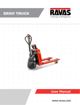
2. DESCRIPTION OF THE PALLET TRUCK
a. Overview of the main components
1. Safety (belly) button
2. Tiller
3. Pin-code panel
4. Discharge indicator and charging indicating
LED
5. Emergency button
6. Hydraulic unit cover
7. Chassis
8. Leg
9. Load roller
10. Battery
11. Apr
on
12. Dr
iving unit
Fig. 1: Overview main components

8
b. Main technical data
Fig. 2: Technical data

9
Table 1:
Type sheet for industrial truck acc. to VDI 2198
Main technical data for standard version
Distinguishing mark
1.2 Manufacturer`s type designation EPT-2745-33
1.3
Power(battery,diesel,petrol gas,manual)
Battery
1.4
Operator type Pedestrian/Stand
1.5
Load Capacity / rated load Q (t) 1.5
1.6
Load centre distance c (mm) 600
1.8
Load distance, centre of drive axle to fork x(mm) 947
1.9
Wheelbase y (mm) 1185
Weight
2.1
Service weight kg 123 126
2.2
Axle loading, laden front/rear kg 500 / 1123 626 / 1000
2.3
Axle loading, unladen front/ rear kg 96 / 27 99 / 27
Tires, chassis
3.1 Tires Polyurethane (PU)
3.2 Tire size, front ∅ x w (mm) ∅ 210×70
3.3 Tire size, rear ∅ x w (mm) ∅ 80×93(∅ 80×70)
3.4 Additional wheels (dimensions) ∅ x w (mm) -/∅ 80×30
3.5 Wheels, number front/ rear(x=driven wheels) 1x/ 2(1x/ 4) or 1x +2/ 2(1x +2/ 4)
3.6 Tread, front b
10
-/420 (mm)
3.7 Tread, rear b
11
380 (mm) 525
Dimensions
4.4 Lift height h
3
115 (mm)
4.9 Height of tiller in drive position min. / max. h
14
700 / 1160 (mm)
4.15 Height, lowered h
13
80 (mm)
4.19 Overall length l
1
1530 (mm)
4.20 Length to face of forks l
2
380 (mm)
4.21 Overall width b
1
540 (mm) 540
4.22 Fork dimensions s/e/l (mm) 47 / 160 / 1150
4.25 Distance between fork-arms b
5
540 (mm) 540
4.32 Ground clearance, centre of wheelbase m
2
33 (mm)
4.34 Aisle width for pallets 800X1200 lengthways Ast(mm) 2000
4.35 Turning radius Wa (mm) 1330
Performance
5.1 Travel speed, laden/ unladen km/h 4.6/ 4.8
5.2 Lift speed, laden/ unladen m/s 0.020 / 0.025
5.3 Lowering speed, laden / unladen m/s 0.05 / 0.04
5.8 Gradeability, laden/ unladen % 4 / 16
5.10 Service brake Electromagnetic
Motors
6.1 Drive motor rating S2 60min kW 0.65
6.2 Lift motor rating at S3 10% kW 0.50
6.3 Battery acc. to DIN 43531 /35 / 36 A, B, C, no
/
6.4 Battery voltage, nominal capacity K5 V/Ah 24 / 20(24 / 30;24 / 36)
6.5 Battery weight (minimum) kg 4.6
6.6 Energy consumption acc. to VDI cycle KWh/h 0.18
8.1 Type of drive control AC -Speed Control
8.4 Sound level at driver`s ear acc. to EN 12053 dB(A) 69

10
c. Description of the safety devices and warning labels
(Europe and other, excepting USA)
For the USA –market, the
description of the safety and
warning labels is mentioned in
chapter 11.
A “No passengers” decal
B Crane hook label
C Identification plate (ID-plate)
D Sticker to read and follow
this instruction
E Sign oil filling point
F Capacity sticker
The truck is equipped with an emergency
switch (5) which stops all lifting-, lowering-,
driving- functions and engages the failsafe
electromagnetic brake when it is pressed. By turn this button clockwise, the truck can be operated after
the controller checked the functions. Before operating, type the password on pin-code panel and press
the √ button.
To prevent against unauthorized access, press emergency switch (5) or press the X button of pin-code
panel.
The truck is equipped with a safety (belly) button (1) which switches the driving function away from the
operator, if the truck travels towards the operator and the tiller is activated in the tillers operating zone.
Follow also the instructions given on the decals. Replace the decals if they are damaged or missing.
Fig. 3: Safety and warning labels

11
d. Identification plate
1 Designation, type
2 Serial number
3 Rated capacity in kg
4 Supply voltage in V
5 Own mass (self weight) in kg without battery
6 Name and address of manufacturer)
7 Battery weight minimum/ maximum
8 Nominal power in kW
9 Load center distance
10 Manufacturing date
11 Option
3. WARNINGS, RESIDUAL RISK AND SAFETY INSTRUCTIONS
DO NOT
• Put foot or hand under or into the lifting mechanism.
• Allow other person than the operator to stand in front of or behind the truck when it is
moving or lifting/lowering.
• Overload the truck.
• Put foot in front of the wheels, injury could result.
• Lift people. People could fall down and suffer severe injury.
• Push or pull loads
• Use this truck on ramps
• Side or end load. Load must be distributed evenly on the forks.
• Use the truck with unstable, unbalanced not stable load.
• Use truck without manufacturer
’
• Lifted loads could become unstable at wind forces. In the case of wind forces do not
lift the load if there is any influence to the stability
s written consent.
Fig. 4: Identification plate
1
2
4
5
3
7
If sold to the EU, here the
place of the CE marking
6
8
9
10
11

12
Watch difference in floor levels when driving. Load could fall down or the truck could get uncontrollable.
Keep watching the condition of load. Stop operating the truck if load becomes unstable.
Brake the truck and activate the emergency button (5) by pushing when sliding load on or off the truck. If
the truck has any malfunctions, follow chapter 10.
Practice maintenance work according to regular inspection. This truck is not designed to be water
resistant. Use the truck under dry condition. Prolonged continuous operation might cause damage of the
power pack. Stop operation if temperature of hydraulic oil is too high.
• When operating the electric pallet truck, the operator has to wear safety shoes.
• The truck is intended to be used for indoor applications with ambient temperatures
between +5°C and + 40°C.
• The operating lighting must be minimum 50 Lux.
• It is not allowed to use the truck on ramps.
• To prevent unintended sudden movements when not operating the truck (i.e. from
another person, etc.), switch off the truck and remove the key.
• Avoid any crashes of the foldable platform against surrounding objects, especially
moving in Fw direction as it may lead to crushing and shearing hazards. Always
maintain safe speed according to the working environment.
4. COMMISSIONING, TRANSPORTING, DECOMMISSIONING
a. Commissioning
Table 2:
Type
Commissioning data
EPT-2045-33(540X1150)
EPT-2745-33(685X1150)
Commissioning
weight [kg]
123kg 126kg
Dimensions [mm]
1530x540x1250 1530x685x1250
After receiving our new pallet truck or for re-commissioning you have to do following before (firstly)
operating the truck:
• Check if are all parts included and not damaged
• Eventually installation of the multifunction tiller
• Eventually installation and charging the batteries (follow chapter 8)
• Do the work according to the daily inspections as well as functional checks.
b. Lifting/ transportation
For transporting, remove the load, lower the forks to the lowest position and fix the truck safe with
dedicated lifting gear according to the following figures.
Lifting
USE DEDICATED CRANE AND LIFTING EQUIPMENT
DO NOT STAND UNDER THE SWAYING LOAD
DO NOT WALK INTO THE HAZARDOUS AREA DURING LIFTING

13
Park the truck securely and lash the truck according to the points identified in Fig. 5. Lift the truck to its
destination and place the truck securely before removing the lifting gear. The lashing points are
according to the Fig. 5.
Transportation
DURING TRANSPORTATION ON A LORRY OR TRUCK ALWAYS FASTEN THE
TRUCK SECURELY
Lower the forks and park the truck securely.
Fasten the truck according to Fig. 6 by fixing dedicated lashing belts to each side of the trucks crane
hook holes and fasten the other side at the transporting truck.
c. Decommissioning
For storage, remove the load, lower the truck to the lowest position, grease all in this handbook
mentioned greasing points (regular inspection), and eventually protect the truck against corrosion and
dust. Remove the batteries and jack the truck safely, so that there will be no flattening after storage.
For final decommissioning hand the truck to a designated recycling company. Oil, batteries and electric
components must be recycled due to legal regulations.
5. DAILY INSPECTION
This chapter describes pre-shift checks before putting the truck into operation.
Daily inspection is effective to find the malfunction or fault on this truck. Check the truck on the following
points before operation.
Remove load from truck and lower the forks.
Fig. 5: Lifting with a crane
Fig. 6: fixing points

14
DO NOT USE THE TRUCK IF ANY MALFUNCTION IS FOUND.
• Check for scratches, deformation or cracks.
• Check if there is any oil leakage from the cylinder.
• Check the vertical creep of the truck.
• Check the smooth movement of the wheels.
• Check the function of the emergency brake by activating the emergency button.
• Check, the tiller arm- switch braking function
• Check the lifting and lowering functions by operating the buttons.
• Check if all bolts and nuts are tightened firmly.
• Visual check if there are any broken electric wires.
• If supplied with a backrest extension, check it for damages and correct assembling.
6. OPERATING INSTRUCTIONS
BEFORE OPERATING THIS TRUCK, PLEASE FOLLOW THE WARNINGS AND
SAFETY INSTRUCTIONS (CHAPTER 3).
M
ake sure, that the load is palletized and stable and that the daily inspection is carried out.
Type the password on pin-code panel and press √ button to start the truck.
Press the horn button (Fig.7,14) to activate the audible warning signal.
a. Parking
DO NOT PARK THE TRUCK ON INCLINED SURFACES
The truck is equipped with an electromagnetic failsafe stopping and parking brake.
Always lower the forks fully. Press the emergency switch (5).
Fig.7: Tiller operating controls

15
b. Lifting
DO NOT OVERLOAD THE TRUCK! THE MAXIMUM CAPACITY IS 1500 kg.
Travel with the lowered forks fully underneath the pallet and press the lifting button (Fig.
7, 15) until you reached the desired lifting height.
c. Lowering
Press the lowering button (22) carefully.
Lower the load until the forks are clear of the pallet, then
drive the truck carefully out of the load unit.
d. Travelling
TRAVEL ON INCLINES ONLY WITH THE LOAD FACING UPHILL.
DO NOT TRAVEL ON INCLINES MORE THAN SPECIFIED WITH THE TECHNICAL
DATA.
After starting the truck by activation from Pin-code panel, move the tiller to the operating zone (‘F’,
Fig.9).
Turn the accelerator button to the desired direction forward ‘Fw.’ or backwards Bw.’(Fig. 9).
Control the travelling speed by moving the accelerator button (Fig.7,13) carefully until you reached the
desired speed. If you move the accelerator button back to the neutral position, the controller decelerates
the truck until the truck stops. If the truck stopped, the parking brake will be engaged.
Drive carefully the truck to the destination. Watch the route conditions and adjust the travelling speed
with the accelerator-button.
Fig. 9: Operating direction
Fig. 8: Load facing uphill

16
Press turtle button (Fig.7,17) to enter into slow speed mode, travel slowly by moving the accelerator
button (Fig.7,13) , press turtle button again to return back to regular mode.
Press turtle button and hold for 2 seconds to realize driving with tiller vertically when in confined area.
e. Steering
You steer the truck by moving the tiller to the left or right side.
f. Braking
THE BRAKING PERFORMANCE DEPENDS ON THE TRACK CONDITONS AND
TRHE LOAD CONDITONS OF THE TRUCK
The braking function can be activated on several ways:
• By moving the accelerator button (13) back to the initial ‘0’ position or by releasing the button, the
regenerative braking is activated. The truck brakes until it stops.
• By moving the accelerator button (13) from one driving direction directly to the opposite direction,
the truck brakes regenerative until it starts travelling into the opposite direction.
• The truck brakes, if the tiller is moved up or down to the braking zones (‘B’). If the tiller is released,
the tiller moves automatically up to the upper baking zone (‘B’).The truck brakes until it stops.
• The safety (belly) button (1) prevents the operator from being crushed. If this button is activated, the
truck decelerates and/ or starts travelling into the backwards direction (‘Bw.’) for a short distance
and stops. Please consider, that this button also operates, if the truck is not travelling and the tiller is
in the operating zone.
g. Malfunctions
If there are any malfunctions or the truck is inoperative, please stop using the truck and activate the
emergency button (5) by pushing it. If possible, park the truck on a safe area and press the X button of
pin-code panel. Inform immediately the manager and, or call your service. If necessary, tow the truck out
of the operating area by using dedicated towing/ lifting equipment.
h. Emergency
In emergencies or in the event of tip over (or off dock), keep safe distance immediately. If possible push
the emergency button (5). All electrical functions will be stopped.

17
7. PIN-CODE PANEL
The truck is equipped optional with a pin-code panel (3).
a. Introduction
Pin-code panel is an electronic system which is similar with an electronic alarm system. Truck will not
able to operate before typing a correct password, the main function is to prevent unauthorized operation.
b. Main parameters
Working voltage:12V-60V
Ambient temperature:-40℃ to +90℃
IP grade:IP65
c. Main functions
Truck can be operated only when correct password is typed.
There are two passwords of pin-code panel, one is the default user password 1234, and you can use it
immediately. The other one is the administrator password 3131; with this you can set a new user
password according to the following steps:
Type “3232”, click “√”.
Type previous user password.
Type new password, and click “√”, previous password will be replaced.
In case you need to reset the password, please follow the procedure under:
Type “123”, click
“√”.
Type “123” again, click “√”. Password will be “1234”.
8. BATTERY CHARGING AND REPLACEMENT
• Only qualified personnel are allowed to service or charge the batteries. The
instructions of this handbook and from the battery- manufacturer must be observed.
• The batteries are lithium batteries.
• Recycling of batteries undergoes national regulations. Please follow these
regulations.
• By handling batteries, open fire is prohibited!
• In the area of battery charging neither burning materials nor burning liquids are
allowed. Smoking is prohibited and the area must be ventilated.
• Park the truck securely before starting charging or installing/changing the batteries
• Before finishing the maintenance work, make sure, that all cables are connected
correctly and that there are no disturbing towards other components of the truck.

18
The truck is equipped with following lithium traction battery- type:
24V
20Ah lithium battery, 4.5kg; 24V30Ah lithium battery, 6kg; 24V36Ah lithium battery, 7kg
IT IS ONLY ALLOWED TO USE LITHIUM
BATTERIES.
PLEASE CONSIDER THE MAXIMUM OPERATING
TEMPERATURE OF THE BATTERIES.
a. Replacement
Park the truck securely and press emergency switch (5). Hold the
battery grip with one finger pull out the lock, and then take out the
battery vertically. The installation is in the reverse order.
b. Battery indicator
Hour meter
An alpha-numeric liquid crystal display is fitted in the centre of the unit that shows the hours worked. The
display is backlight (the backlight is normally lighted).
A
larms
The same display can also indicate the alarm state, showing a code corresponding to the type of alarm.
Battery State of charge
The battery's state of charge indication is integrated in the LCD display; it is shown by ten notches. Each
notch represent the 10% of the battery charge. As the battery becomes discharged, the notches turn off
progressively, one after the other, in proportion to the value of the residual battery charge. This value,
sent to the MDI-CAN by the controller via CAN-BUS. When BATTERY LOW alarm appears on the
Fig. 10: Battery replacement
Fig. 11: Battery discharge indicator
Battery discharged
Battery charged

19
controller, the battery symbol which is under the notches blinks.
T
urtle Symbol:
It is normally off, when it appears (fixed) it shows activation of the “soft” mode of the truck, in which
maximum speed and acceleration are reduced.
M
onkey Wrench Symbol:
It is normally off, when it appears (fixed) it shows the request of programmed maintenance or the alarm
state. In this case the relative code will be displayed. The information supplied by the MDI-CAN can be
extremely useful. Failures can be quickly identified by the operator or service technician thereby finding
the fastest solution to the problem.
Hourglass Symbol:
It blinks when the hour meter is working.
c. Charging
• Before charging ensure that you are using an appropriate charger for charging the
installed battery!
• Before using the charger, please fully understand the instructions of the charger
instructions.
• Always follow these instructions!
• The room, where you are charging must be ventilated.
• The exactly charge status can be only checked from the discharge indicator. To
control the status, the charging must be interrupted and the truck must be started.
Park the truck at a dedicated secured area with a
dedicated power supply.
Lower the forks and remove the load;
Switch the truck off and connect the charger plug (19) to
the charging port (20) on the battery. The charger starts
charging the battery if the charger plug (18) is connected
to the main power supply.
Disconnect the charger plug from the battery and close
the cap after the charger finished charging.
When charging is finished, disconnect the plug (18) from
the socket and place it in the designated pocket.
I
t’s also allowed to remove the battery out and charge in
dedicated area.
Table 3:
LED- signal
LED-Status
Function
Fig.12: Battery charging

20
Red
Charging
Green
Fully charged
Table 4: Charger
9. REGULAR MAINTENANCE
• Only qualified and trained personnel are allowed to do maintenance on this truck.
• Before maintaining, remove the load from the forks and lower the forks to the
lowest position.
• If you need to lift the truck, follow chapter 4b by using designated lashing or jacking
equipment. Before working, put safety devices (for instance designated lift jacks,
wedges or wooden blocks) under the truck to protect against accidental lowering,
movement or slipping.
• Please pay attention by maintain the tiller arm. The gas pressure spring is
pre-loaded by compression, carelessness can cause injury.
• Use approved and from your dealer released original spare parts.
• Please consider that oil leakage of hydraulic fluid can cause failures and accidents.
• It is allowed to adjust the pressure valve only from trained service technicians.
If you need to change the wheels, please follow the instructions above. The castors must
be round and they should have no abnormal abrasion.
Check the items emphasized maintenance checklist.
a. Maintenance checklist
Table 5: Maintenance checklist
Interval(Month)
1 3 6 12
Hydraulic
1 Check the hydraulic cylinder(s), piston for damage noise and leakage
•
2 Check the hydraulic joints for damage and leakage
•
3 Inspect the hydraulic oil level, refill if necessary
•
4 Refill the hydraulic oil ( 12 month or 1500 working hours )
•
5 Check and adjust function of the pressure valve (1500kg+0/+10%)
•
Mechanical system
6 Inspect the forks for deformation and cracks
•
7 Check the chassis for deformation and cracks
•
8 Check if all screws are fixed
•
Model Specification
BZ5731J3
29.4V5A(China)
DZL300SS02
29.4V8A(China)
SSLC300V29
29.4V8A(EU)
SSLC300V29
29.4V8A(US)

21
9 Check the push rods for deformation and damages
•
10 Check the gearbox for noise and leakage
•
11 Inspect the wheels for deformation and damages
•
12 Inspect and lubricate the steering bearing
•
13 Inspect and lubricate the pivot points
•
14 Lubricate the grease nipples
•
Electrical system
15 Inspect the electric wiring for damage
•
16 Check the electric connections and terminals
•
17 Test the Emergency switch function
•
18 Check the electric drive motor for noise and damages
•
19 Test the display
•
20 Check, if correct fuses are used
•
21 Test the warning signal
•
22 Check the contactor(s)
•
23 Check the frame leakage (insulation test)
•
24 Check function and mechanical wear of the accelerator
•
25 Check the electrical system of the drive motor
•
Braking system
26 Check brake performance, if necessary replace the brake disc or adjust the air gap
•
Battery
27 Check the battery voltage
•
28 Clean and grease the terminals and check for corrosion and damage
•
29 Check the battery housing for damages
•
Charger
30 Check the main power cable for damages
•
31 Check the start-up protection during charging
•
Function
32 Check the horn function
•
33 Check the air gap of the electromagnetic brake
•
34 Test the emergency braking
•
35 Test the reverse and regenerative braking
•
36 Test the safety (belly) button function
•
37 Check the steering function
•
38 Check the lifting and lowering function
•
39 Check the tiller arm switch function
•
General
40 Check if all decals are legible and complete
•
41 Inspect the castors, adjust the height or replace these if worn out.
•
42 Carry out a test run
•

22
b. Lubricating points
Lubricate the marked points according to the maintenance checklist. The required grease specification is:
DIN 51825, standard grease.
c. Check and refill hydraulic oil
It is recommended to use hydraulic oil in connection with average temperature:
Environment temperature
–5℃~25℃ >25℃
Type
HVLP 32,
DIN 51524
HLP 46,
DIN 51524
Viscosity
28.8-35.2 41.4 - 47
Amount
0.4L
W
aste material like oil, used batteries or other must be probably disposed and recycled according to the
national regulations and if necessary brought to a recycling company.
The oil level height shall be in the not lifted position min. 0.3L to 0.5L.
If necessary add oil at the filling point.
1. Load roller bearing
2. Cylinder
3. Axle
4. Bearing
5. Gear box
6. Side roller bearing
7. Connection point
Fig. 13: Lubricating points
/