
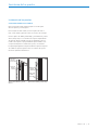
Designer Series
Undercounter Refrigeration
Installation Guide
SPECIFICATIONS, INSTALLATION,
AND MORE

2 | Sub-Zero Customer Care 800.222.7820
Designer Series Undercounter Refrigeration
Contents
3 Designer Series Undercounter Refrigeration
4 Opening Dimensions
5 Electrical Requirements
6 Plumbing Requirements
6 Preparation
7 Anti-Tip Bracket
7 90° Door Stop
8 Placement
8 Alignment
9 Water Line
10 Door Panel
12 Panel Installation
14 Completion
Features and specifications are subject to change at any
time without notice. Visit subzero.com/specs for the most
up-to-date information.
Important Note
To ensure this product is installed and operated as safely
and eciently as possible, take note of the following types
of highlighted information throughout this guide:
IMPORTANT NOTE highlights information that is especially
important.
CAUTION indicates a situation where minor injury or prod-
uct damage may occur if instructions are not followed.
WARNING states a hazard that may cause serious injury or
death if precautions are not followed.
IMPORTANT NOTE: Throughout this guide, dimensions in
parentheses are millimeters unless otherwise specified.
IMPORTANT NOTE: Save these instructions for the local
electrical inspector.

subzero.com | 3
Designer Series Undercounter Refrigeration
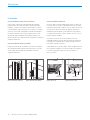
Product Information
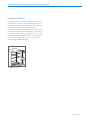
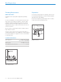
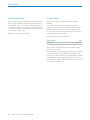
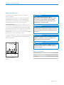
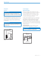
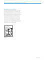
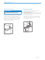
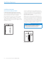
Important product information, including the model and
serial number, are listed on the product rating plate. The
rating plate is located inside the cabinet, in the upper left
area of the unit. Refer to the illustration below.
If service is necessary, contact Sub-Zero Factory Certified
Service with the model and serial number. For the name of
the nearest Sub-Zero Factory Certified Service or for ques-
tions regarding the installation, visit the Product Support
section of our website, subzero.com, or call Sub-Zero
Customer Care at 800-222-7820.
RATING PLATE
Rating plate location

4 | Sub-Zero Customer Care 800.222.7820
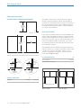
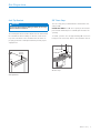
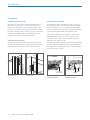
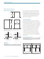
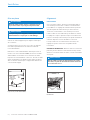
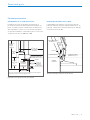
The depth of each model is 23⁄" (587). Allow for panel
thickness when planning the finished opening depth. A
minimum 3⁄"
(89) finished return is required on all sides of
the opening. Framed cabinets require additional finished
filler material behind the face frame for a proper installa-
tion. Refer to the illustration.
DUAL INSTALLATION
If two units are installed side by side, a dual installation kit
may be required. Installations without a custom filler strip
require a dual installation kit. If a dual installation kit is not
specified, a 2"
(51) filler strip is recommended between the
units. Dual installations without a filler strip can only be
accomplished using two units with opposite hinges. Refer
to the illustrations below.
Dual installation kits are available through an authorized
Sub-Zero dealer. For local dealer information, visit the find
a showroom section of our website, subzero.com. For
questions regarding the installation, call Sub-Zero Cus-
tomer Care at 800-222-7820.
DUAL OPENING WIDTH W
Two 24" Models 48" (1219)
Dual installation kit required.
Site Preparation
Opening Dimensions
DESIGNER SERIES UNDERCOUNTER MODELS
W
OPENING WIDTH
H
OPENING
HEIGHT
TOP VIEW
SIDE
VIEW FRONT VIEW
NOTE:
3
1
/2" (89) finished returns will be visible and should be finished to match cabinetry.
3
/4" (19)
TYPICAL
FRAMED
CABINETRY
W
FILLER
3
1
/2" (89)
FINISHED
RETURN
FRAMELESS
CABINETRY
W
3
/4" (19)
TYPICAL
3
1
/2" (89)
FINISHED
RETURN
24" (610)
OPENING
DEPTH
WITHOUT FILLER STRIP
FILLER STRIP
Opposite hinges
Same side hinges
OPENING DIMENSIONS W H
24" Model 24" (610) 34⁄" (876)

subzero.com | 5
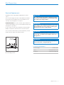
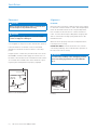
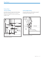
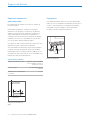
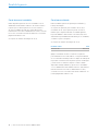
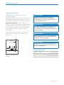
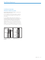
Electrical Requirements
Installation must comply with all applicable electrical
codes.
The electrical supply must be located within the shaded
area shown in the illustration below. A separate circuit
servicing only this appliance is required.
IMPORTANT NOTE: For indoor models, a ground fault cir-
cuit interrupter (GFCI) is not recommended and may cause
interruption of operation.
For the outdoor model, a ground fault circuit interrupter
(GFCI) is required to reduce the risk of electrical shock.
The electrical outlet must be positioned with the ground-
ing prong to the right of the thinner blades.
1
/4" (6)
4"
(102)
3"
(76)
9"
(229)
FLOOR
RIGHT SIDE
OF OPENING
Electrical supply location
CAUTION
The outlet must be checked by a qualified electrician
to be sure it is wired with the correct polarity. Verify
the outlet is properly grounded.
WARNING
If the supply cord is damaged, it must be replaced by
the manufacturer, its service agent or similarly quali-
fied persons in order to avoid a hazard.
WARNING
Do not locate multiple portable socket-outlets,
power strip, or portable power supplies at the rear of
the appliance.
WARNING
Do not use an extension cord, two-prong adapter, or
remove the power cord ground prong.
ELECTRICAL REQUIREMENTS
Electrical Supply 115 VAC, 60 Hz
Service 15 amp dedicated circuit
Receptacle 3-prong grounding-type
Site Preparation

6 | Sub-Zero Customer Care 800.222.7820
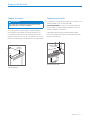
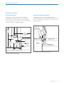
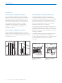
Plumbing Requirements
MODEL DEU2450CI
Installation must comply with all applicable plumbing
codes.
For ease of installation, recess the water shut o into the
wall or place it in an adjacent cabinet. Locate the water
supply line within the shaded area shown in the illustra-
tion below. Connect the water supply line to the house
supply with an easily accessible shut-o valve. Do not use
self-piercing valves.
An in-line filter is required when water conditions have a
high sediment content.
A reverse osmosis system can be used provided there is
constant water pressure of 35–120 psi
(2.4–8.3 bar) supplied
to the unit at all times. A copper line is not recommended
for this application.
PLUMBING REQUIREMENTS
Water Supply Line ⁄" OD copper, braided
stainless steel, or PEX tubing
Water Pressure 35–120 psi (2.4–8.3 bar)
Excess Water Line for Connection 5' (1.5 m)
Preparation
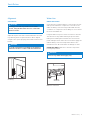
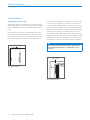
Uncrate the unit and inspect for damage. Remove and
recycle packing materials. Do not discard the kickplate,
anti-tip bracket, and hardware.
Remove the kickplate by extracting the two mounting
screws. Refer to the illustration below.
SCREW
Kickplate removal
4"
(102)
3"
(76)
9"
(229)
LEFT SIDE
OF OPENING
AREA EXTENDS
1
/2" (13)
FORWARD ON FLOOR
Water supply location
Site Preparation

subzero.com | 7
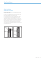
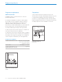
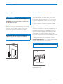
90° Door Stop
The door stop pins provided with the unit limit the door
swing to 90°.
IMPORTANT NOTE: If a 90° door opening is desired, the
pins must be installed prior to installing the unit into the
opening.
To install, open the door to approximately 80°. Insert one
hinge pin into each hinge. Refer to the illustration below.
DOOR STOP PIN
90° door stop
Anti-Tip Bracket
WARNING
To prevent the unit from tipping forward, the anti-tip
bracket must be installed.
The anti-tip bracket should be attached to the wall behind
the unit with the bracket flange located ⁄"
(6) above the
top of the unit. Refer to the illustration below. Failure to
properly position the anti-tip bracket will prevent proper
engagement.
1
/4" (6)
ANTI-TIP
BRACKET
Anti-tip bracket
Site Preparation

8 | Sub-Zero Customer Care 800.222.7820
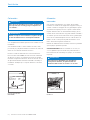
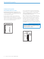
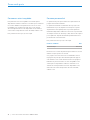
Alignment
LEVELING
Once the unit is in position, rotate the front legs clockwise
to raise and counterclockwise to lower. Rear height adjust-
ment can be made from the front. Using a Phillips drive,
turn clockwise to raise the unit or counterclockwise to
lower. Use the lowest torque setting when using a power
drill. Do not turn the leveling legs by hand. Refer to the
illustration below.
When the unit is properly leveled, door adjustments are
less likely to be necessary.
IMPORTANT NOTE: Level the unit to the floor, not the
surrounding cabinetry. This could aect the operation of
the unit, such as door closing.
WARNING
To reduce the possibility of the unit tipping forward,
the front leveling legs must be in contact with the
floor.
REAR
ADJUSTMENT
FRONT
ADJUSTMENT
Leveling
Installation
Placement
CAUTION
Before moving the unit into position, secure the door
closed and protect any finished flooring.
WARNING
When positioning the appliance, ensure the supply
cord is not trapped or damaged.
Use an appliance dolly to move the unit near the opening.
If the unit has been on its back or side, it must stand
upright for a minimum of 24 hours before connecting
power.
Plug the power cord into the grounded outlet. For model
DEU2450CI, insert the water supply line into the hole on
the back of the unit. Refer to the illustration below. Pull the
excess water line forward as the unit is slid into the open-
ing. Verify the anti-tip bracket is properly engaged.
BACK OF UNIT
HOLE FOR
WATER LINE
Water line (model DEU2450CI)

subzero.com | 9
Water Line
MODEL DEU2450CI
Under the unit, ⁄" plastic tubing is connected to the unit
with a preassembled ⁄" compression connection. The
water line fitting connection kit, provided with the unit,
contains a ⁄" compression union fitting for connection to
the household water line.
Purge the water line prior to final connection to the unit.
This will remove any debris that may be present in the
tubing from installing the new water line. Connect the
plastic tubing from the unit to the house water supply line
with the fitting connection kit provided. Refer to the
illustration below. Check all water line fittings for leaks.
IMPORTANT NOTE: Water lines cannot be exposed to
freezing temperatures.
WARNING
Connect to potable water supply only.
WATER LINE
CONNECTION
Water line connection
Installation
Alignment
ANCHORING
CAUTION
If using a power drill to predrill holes or install
screws, verify the drill chuck does not contact the
units face frame.
Adjust the depth of the unit to fit flush with the surround-
ing cabinetry. Allow for panel thickness. Once aligned,
verify the door opens properly, then install screws in each
bracket.
WARNING
To avoid a hazard due to instability of the appliance,
it must be fixed in accordance with the instructions.
Anchoring

10 | Sub-Zero Customer Care 800.222.7820
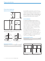
Custom Panel
A custom door panel and handle hardware must be
installed.
A ⁄"
(16) minimum to ⁄" (19) maximum thick panel is
required. The panel cannot exceed the maximum panel
weight indicated in the chart below. The depth of each
model is 23⁄"
(587). Allow for panel thickness when plan-
ning the finished opening depth.
Minimum ⁄"
(3) reveals are required.
PANEL WEIGHT MAX
24" Model 22 lb (10 kg)
Finish all sides of the custom panel. They will be visible
when the door is open.
A D-style handle is recommended. Locate the door handle
near the edge of the panel opposite the hinge and cen-
tered top to bottom. Stainless steel tubular and pro handles
are avail able through an authorized Sub-Zero dealer. For
local dealer information, visit the find a showroom section
of our website, subzero.com.
Door Panel
Stainless Steel Panel
Stainless steel panels are available through an authorized
Sub-Zero dealer. Stainless steel panels include a stainless
steel kickplate cover. The outdoor model requires the use
of a Sub-Zero stainless steel outdoor accessory panel. For
local dealer information, visit the find a showroom section
of our website, subzero.com.
Minimum ⁄"
(3) reveals are required.

subzero.com | 11
Custom Panel
TOE KICK CLEARANCE
The height of the toe kick area can extend beyond the
typical toe kick height, provided it does not exceed the
dimensions in the illustration below. For questions
regarding the installation, call Sub-Zero Customer Care
at 800-222-7820.
Door Panel
MAXIMUM DOOR OPENING
As the panel width and/or depth increases, so does the
potential for panel interference. Interference may be
minimized by using the 90° door stop.
3
/8" (10)
DOOR CLOSED
3
/4" (19) PANEL
1
/
8
"
(3) REVEAL
ADJACENT
CABINETRY
DOOR
OPEN
90°
DOOR OPEN
MAXIMUM 115°
Maximum door opening (top view)
DOOR
PANEL
HINGE
23
1
/
8
"
(587)
TO BACK OF UNIT
2" (51)
TO
4
1
/2" (114)
FROM
FLOOR
3
1
/2" (89)
MAX DEPTH
1
1
/8" (29)
KICKPLATE
ADJUSTMENT
34
1
/2" (876)
TYPICAL
PRODUCT
HEIGHT
DECORATIVE KICKPLATE
CANNOT EXTEND
BEYOND THIS
POINT
3
3
/8" (86)*
DECORATIVE
KICKPLATE
HEIGHT
*Not included. Dimension will vary as the product height increases or decreases
from the typical product height.
Toe kick clearance (side view)

12 | Sub-Zero Customer Care 800.222.7820
Panel Installation
Panel Installation
DOOR PANEL INSTALLATION
Typical panel dimensions are based on an 34⁄"
(876) fin-
ished height with ⁄"
(3) reveals. Placement of the template
must be adjusted for panels exceeding the typical dimen-
sions.
Place the panel face down on a protected work surface.
Position the template flush with the top and sides of the
panel. Verify the correct side of the template is being used,
then mark and drill holes. Refer to the illustration below.
Use a Torx drive to partially insert a #8 x ⁄" screw into the
second hole from the top on each side of the panel. The
screws should be approximately ⁄"
(4) proud of the panel
and will support the weight of the panel during installation.
Align the support screws on the back of the panel with the
slotted holes on both door mounting brackets. Refer to
the illustration below. Opening the door slightly may help
with alignment. Once the panel is supported by the screws,
partially insert a #8 x ⁄" screw into the second hole from
the bottom on each side of the panel, but do not tighten.
CAUTION
As reveals between cabinetry and the unit decrease,
severe finger pinching can occur while the door is
closing.
TOP OF DOOR PANEL
TOP OF DOOR PANEL
LEFT SIDE DOOR PANEL
RIGHT SIDE DOOR PANEL
Door panel template
BACK OF PANEL
Door panel mounting

subzero.com | 13
Panel Installation
DOOR PANEL ADJUSTMENT
Close the door. Make any necessary adjustments to align
the panel and reveals.
For side-to-side adjustment, move the panel side to side,
then install and tighten all mounting screws.
For up-and-down and in-and-out adjustments, slightly
loosen the bracket screws. Depending on the level of
adjustment required, it may be helpful to loosen all of the
bracket screws which will allow for maximum adjustment.
Once the bracket screws are loosened, use a wrench to
rotate the cams to make adjustments. After the adjust-
ments have been made, tighten all bracket screws. Refer to
the illustrations below.
Panel Installation
BRACKET
SCREWS
IN-AND-OUT
CAM
BRACKET
SCREWS
UP-AND-DOWN
CAM
In-and-out adjustment
Up-and-down adjustment

14 | Sub-Zero Customer Care 800.222.7820
KICKPLATE INSTALLATION
The kickplate must be removable for service. The floor
cannot interfere with removal. Finger-tighten the adjust-
ment bracket nuts. Refer to the illustration below. Make
in-and-out adjustments, then wrench-tighten the bracket
nuts. Install the kickplate with the provided screws.
A decorative kickplate can be attached to the factory-
installed kickplate. The three rows of vented louvers
cannot be covered. A decorative kickplate cannot be
attached to the outdoor model.
To install a decorative kickplate, remove the paper backing
from the magnets and attach the decorative kickplate to
the magnets. The magnets allow the decorative kickplate
to be removed if necessary.
Completion
DOOR TRIM INSTALLATION
After the door panel has been adjusted, install the deco-
rative side trim to the door. To install, start at the top
and align the trim with the front and rear flanges on the
bracket, then snap into place by pushing the trim toward
the back of the panel. Once the top is secure, continue the
installation downward until the remaining trim is com-
pletely secure. Refer to the illustration below.
SIDE TRIM INSTALLATION
Install the decorative trim strip to the handle side of the
unit. The side trim snaps over the brackets attached to the
handle side of the unit. Refer to the illustration below.
Installation
Door side trim
Unit side trim
KICKPLATE
ADJUSTMENT
SCREW
MAGNET
Kickplate adjustment
Kickplate installation

subzero.com | 15
Sub-Zero, Sub-Zero & Design, Sub-Zero & Snowflake Design, Dual Refrigeration, The Living Kitchen, Great American Kitchens The Fine Art of Kitchen Design, Wolf, Wolf &
Design, Wolf Gourmet, W & Design, red colored knobs, Cove, and Cove & Design are registered trademarks and service marks of Sub-Zero Group, Inc. and its subsidiaries.
All other trademarks are property of their respective owners in the United States and other countries.
Installation
Completion
WARNING
Follow all city and state laws when storing, recycling,
or discarding unused refrigerators and freezers.

2 | Atención al cliente de Sub-Zero 800.222.7820
Refrigeración bajo mostrador de la Serie de Diseño
Contenido
3 Refrigeración bajo mostrador de la Serie de Diseño
4 Dimensiones de abertura
5 Requisitos eléctricos
6 Requisitos de plomería
6 Preparación
7 Soporte antivuelco
7 Tope para puerta a 90°
8 Colocación
8 Alineación
9 Línea de agua
10 Panel de la puerta
12 Instalación del panel
14 Finalización
Las características y especificaciones están sujetas a
cambios sin previo aviso. Visite subzero.com/specs para
obtener la información más actualizada.
Aviso importante
Para garantizar que este producto se instale y opere de
la forma más segura y eficiente posible, tome nota de los
siguientes tipos de información resaltada en este manual:
AVISO IMPORTANTE señala la información que es
especialmente importante.
PRECAUCIÓN indica una situación en la que se pueden
sufrir heridas leves o provocar daños al producto si no se
siguen las instrucciones.
ADVERTENCIA indica peligro de que se produzcan heridas
graves o incluso la muerte si no se siguen las precauciones.
AVISO IMPORTANTE: En toda esta guía, las dimensiones
entre paréntesis son milímetros, a menos que se
especifique lo contrario.
AVISO IMPORTANTE: Guarde estas instrucciones para el
inspector eléctrico local.

subzero.com | 3
Refrigeración bajo mostrador de la Serie de Diseño
Información del producto
La información importante del producto, incluidos el
modelo y el número de serie de la unidad, se encuentra
en la placa de datos del producto. La placa de datos
se encuentra dentro del gabinete, en el área superior
izquierda de la unidad. Consulte la siguiente ilustración.
Si necesita servicio, póngase en contacto con el centro
de servicio autorizado de Sub-Zero y tenga a la mano el
modelo y número de serie de la máquina. Para obtener
los datos del centro de servicio autorizado de Sub-Zero
más cercano o si tiene preguntas acerca de la instalación,
visite la sección de soporte técnico en nuestra página de
Internet subzero.com o llame a la línea de atención al
cliente de Sub-Zero al 800-222-7820.
PLACA DE DATOS
Ubicación de la placa de datos

4 | Atención al cliente de Sub-Zero 800.222.7820
La profundidad de cada modelo es de 23⁄" (587). Para
determinar la profundidad de la abertura ya con acabados,
considere el grosor del panel. Se necesita un tubo de
retorno de 3⁄"
(89) con acabados en todos los lados de la
abertura. Los gabinetes con marco necesitan material de
relleno de acabado detrás del marco frontal para lograr
una instalación adecuada. Consulte la ilustración.
INSTALACIÓN DOBLE
Si se instalan dos unidades lado a lado, puede ser
necesario un kit de instalación doble. Las instalaciones
sin una tira de relleno personalizada requieren un kit de
instalación doble. Si el uso de un kit de instalación doble
no está especificado, se recomienda utilizar una tira de
relleno de 2"
(51) entre las unidades. Las instalaciones
dobles sin una tira de relleno solo se pueden realizar
cuando se utilizan dos unidades con bisagras opuestas.
Revise las siguientes ilustraciones.
Los kits de instalación doble están disponibles a través
de un distribuidor autorizado de Sub-Zero. Para obtener
más información acerca de los distribuidores locales,
consulte la sección “encuentre una sala de exhibición” en
nuestra página web subzero.com. Para preguntas sobre
la instalación, comuníquese con la línea de atención al
cliente de Sub-Zero al 800-222-7820.
ANCHURA DE ABERTURA DOBLE W
Dos modelos de 24" 48" (1219)
Se requiere kit de instalación doble.
Preparación del sitio
Dimensiones de abertura
MODELOS BAJO MOSTRADOR
ANCHO DE LA
ABERTURA
W
ALTURA DE LA
ABERTURA
H
VISTA SUPERIOR
VIST
A LATERAL VISTA FRONTAL
NOTA: Los tubos de retorno de
3
1
/2" (89) con acabados se podrán ver y se deben
ter
minar para que se ajusten a los gabinetes.
TÍPICO
DE
3
/4" (19)
GABINETE
CON MARCO
W
RELLENO
TUBO DE
RETORNO
DE
3
1
/2" (89)
CON ACABADOS
GABINETES
SIN MARCO
W
TÍPICO
DE
3
/4" (19)
TUBO DE
RETORNO
DE
3
1
/2" (89)
CON ACABADOS
PROFUNDIDAD DE
LA ABERTURA
DE
24" (610)
SIN TIRA DE RELLENO
TIRA DE RELLENO
Bisagras opuestas
Bisagras en el mismo lado
DIMENSIONES DE ABERTURA W H
Modelo de 24" 24" (610) 34⁄" (876)

subzero.com | 5
Requisitos eléctricos
La instalación debe cumplir con todos los códigos
eléctricos vigentes.
El suministro eléctrico debe colocarse dentro del área
sombreada que se muestra en la siguiente ilustración.
Se necesita un circuito independiente que le suministre
electricidad únicamente a este electrodoméstico.
AVISO IMPORTANTE: Para los modelos internos, no es
recomendable utilizar un interruptor circuito de fallos de
conexión a tierra (Ground Fault Circuit Interrupter, GFCI),
ya que puede interrumpir el funcionamiento de la unidad.
Para los modelos externos, es necesario instalar un
interruptor de circuito de fallos de conexión a tierra (GFCI)
para reducir el riesgo de descarga eléctrica.
El tomacorriente eléctrico debe colocarse de tal forma que
la clavija con conexión a tierra quede a la derecha de las
aspas más delgadas.
1
/4" (6)
4"
(102)
3"
(76)
9"
(229)
SUELO
LADO DERECHO
DE LA ABERTURA
Ubicación del suministro
eléctrico
PRECAUCIÓN
Un electricista calificado debe revisar el
tomacorriente para asegurarse de que la conexión
del cableado se haya realizado con la polaridad
correcta. Compruebe que el tomacorriente esté
debidamente conectado a tierra.
ADVERTENCIA
Si el cable de alimentación está dañado, debe ser
reemplazado por el fabricante, su agente de servicio
o personas calificadas de manera similar para evitar
un peligro.
ADVERTENCIA
No coloque múltiples tomas de corriente, enchufe
múltiple o suministros eléctricos portátiles en la
parte posterior del electrodoméstico.
ADVERTENCIA
No use un cable de extensión, adaptador de dos
clavijas ni retire la clavija con conexión a tierra del
cable de corriente.
REQUISITOS ELÉCTRICOS
Suministro eléctrico 115 V CA, 60 Hz
Servicio Circuito dedicado de 15 amperes
Receptáculo Conexión a tierra de 3 clavijas
Preparación del sitio

6 | Atención al cliente de Sub-Zero 800.222.7820
Requisitos de plomería
MODELO DEU2450CI
La instalación debe cumplir con todos los códigos de
plomería vigentes.
Para facilitar la instalación, empotre en la pared la
válvula de cierre de agua o colóquela en un gabinete
adjunto. Localice la línea de suministro de agua en la
zona sombreada que se muestra en la ilustración a
continuación. Conecte la línea de suministro de agua al
suministro de la casa con una válvula de cierre de fácil
acceso. No utilice válvulas autoperforantes.
Se requiere un filtro en línea cuando las condiciones del
agua tienen un alto contenido de sedimentos.
Se puede utilizar un sistema de ósmosis inversa siempre
y cuando la presión del agua que llegue a la unidad se
mantenga de forma constante entre 35 y 120 psi (de 2.4
a 8.3 bares) en todo momento. No es recomendable usar
tuberías de cobre para esta aplicación.
REQUISITOS DE PLOMERÍA
Tuberías de suministro de agua Tubería de cobre, trenzada de
acero inoxidable o PEX de ⁄"
de diámetro exterior
Presión del agua De 35 a 120 psi (de 2.8 a
8.3bares)
Tubería de exceso de agua para
la conexión
5' (1.5 m)
Preparación
Desembale la unidad e inspeccione si tiene algún daño.
Retire y recicle los materiales de embalaje. No deseche el
zócalo, el soporte antivuelco ni las piezas de montaje.
Para quitar el zócalo extraiga los dos tornillos para
montaje. Consulte la siguiente ilustración.
TORNILLO
Extracción del zócalo
4"
(102)
3"
(76)
9"
(229)
LADO IZQUIERDO
DE LA ABERTURA
EL ÁREA SE EXTIENDE
1
/2" (13)
EN EL SUELO
Ubicación del suministro de
agua
Preparación del sitio
Page is loading ...
Page is loading ...
Page is loading ...
Page is loading ...
Page is loading ...
Page is loading ...
Page is loading ...
Page is loading ...
Page is loading ...
Page is loading ...
Page is loading ...
Page is loading ...
Page is loading ...
Page is loading ...
Page is loading ...
Page is loading ...
Page is loading ...
Page is loading ...
Page is loading ...
Page is loading ...
Page is loading ...
Page is loading ...
Page is loading ...
Page is loading ...
-
 1
1
-
 2
2
-
 3
3
-
 4
4
-
 5
5
-
 6
6
-
 7
7
-
 8
8
-
 9
9
-
 10
10
-
 11
11
-
 12
12
-
 13
13
-
 14
14
-
 15
15
-
 16
16
-
 17
17
-
 18
18
-
 19
19
-
 20
20
-
 21
21
-
 22
22
-
 23
23
-
 24
24
-
 25
25
-
 26
26
-
 27
27
-
 28
28
-
 29
29
-
 30
30
-
 31
31
-
 32
32
-
 33
33
-
 34
34
-
 35
35
-
 36
36
-
 37
37
-
 38
38
-
 39
39
-
 40
40
-
 41
41
-
 42
42
-
 43
43
-
 44
44


Sub-Zero DEU2450WL Installation guide
- Type
- Installation guide
- This manual is also suitable for
Ask a question and I''ll find the answer in the document
Finding information in a document is now easier with AI
in other languages
- français: Sub-Zero DEU2450WL Guide d'installation
- español: Sub-Zero DEU2450WL Guía de instalación
Related papers
-
Sub Zero 7025348 Installation guide
-
Sub-Zero DEU2450WL Installation guide
-
Sub-Zero IW30CILH Installation guide
-
Sub-Zero 5310341 Installation guide
-
-
Sub-Zero IT-36CIID-LH Installation guide
-
-
Sub-Zero UC-24BG/S/PH-RH Installation guide
-
-
Sub-Zero WS-30/S/PH-LH Installation guide
Other documents
-
 Frost King SB36W Installation guide
-
 Frost King EZ36W Installation guide
-
Monogram ZK3SN369VLH User manual
-
Cove DW2450 Design Guide
-
-
Everbilt HC11SFE-NP-U1 Installation guide
-
Avallon ADKP30SS Stainless Steel Dual Unit User manual
-
Milescraft 12130713 Installation guide
-
-
Savant SVTFC22440LBE200 Deployment Guide

