
DB 6520
Installation
User Manual

Copyright © 2014 ADB Broadband S.p.A. All rights reserved. This document contains ADB proprietary and confidential
information. No part of this document may be copied, reprinted or reproduced in any material form or electronically,
whether wholly or in part, and no information contained herein may be used or disclosed to third parties unless under a
previous written agreement with ADB Broadband S.p.A setting forth relevant terms and conditions.
Trademarks:
All terms used in this document that are known to be trademarks or service marks have been noted as such. ADB cannot
attest to the accuracy of this information. Other product and corporate names used in this document that may be trade-
marks or service marks of other companies are used only for explanation and to the owner’s benefit, without intent to in-
fringe. Use of a term in this document should not be regarded as affecting the validity of any trademark or service mark.
This publication is subject to change without notice. ADB reserves the right to make changes to equipment design and
system components as well as system documentation and literature as progress in engineering, manufacturing methods,
or other circumstances may warrant.
This publication is intended solely for informational and instructional purposes. Refer to the above as to its possible uses. It
constitutes neither a contract with the user hereof nor a warranty or guarantee with regard to any of the ADB products
described herein nor shall it be construed to grant a license or any other rights under any proprietary rights to information
or material included herein. ADB hereby expressly disclaims any warranty or guarantee, whether express or implied, with
regard to items described herein. Any contract, license, or warranty between ADB and the user hereof is created solely by
separate legal documents.

DB 6520
© (2014) ADB Broadband S.p.A. All Rights Reserved. Proprietary Use Pursuant to Cover Page Instructions.
i
CONTENTS
Welcome 1
About this Guide 1
Naming Convention 1
Conventions 1
Introduction 3
Introduction 3
Package Contents 3
Router Advantages 5
Minimum System and Component Requirements 5
Front Panel 6
Rear Panel 7
Router Installation 10
Introduction 10
Positioning the Router 10
Installing Micro Filters 11
Powering up the router 12
Connecting the Router 12
Technical Specifications 23
Glossary 25

© (2014) ADB Broadband S.p.A. All Rights Reserved. Proprietary Use Pursuant to Cover Page Instructions.
Welcome 1
Welcome
Welcome
ABOUT THIS GUIDE
This guide describes how to install and configure the DB 6520 product. This
guide is intended for use by those responsible for installing and setting up net-
work equipment; consequently, it assumes a basic working knowledge of LANs
(Local Area Networks) and Internet Routers. This guide can be used also for
variants derived from this DB 6520, which are named respectively DB 6220
(which do not provide dual-band radio) and DV 6220 (which do not provide
VDSL bonded functionality).
NAMING CONVENTION
Throughout this guide, the DB 652 is referred to as the “ADSL Wi-Fi Router” or
the “Router”. Category 5 Ethernet Cable is referred to as Ethernet Cable
throughout this guide.
CONVENTIONS
Table 1 and Table 2 list conventions that are used throughout this guide.

DB 6520
© (2014) ADB Broadband S.p.A. All Rights Reserved. Proprietary Use Pursuant to Cover Page Instructions.
2 Welcome
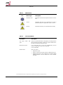
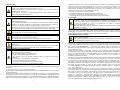
TABLE 1. Notice Icons
Icon
Notice Type
Description
Information note
Information that describes important features or instruc-
tions.
Caution
Information that alerts you to potential loss of data or
potential damage to an application, system, or device.
Warning
Information that alerts you to potential personal injury.
TABLE 2. Text Conventions
Convention
Description
The words “enter” and
“type”
When you see the word “enter” in this guide, you must type some-
thing, and then press Return or Enter. Do not press Return or En-
ter when an instruction simply says “type.”
Keyboard key names
If you must press two or more keys simultaneously, the key
names are linked with a plus sign (+). Example:
Press Ctrl+Alt+Del
Words in italics
Italics are used to:
Emphasize a point.
Denote a new term at the place where it is defined in the text.
Identify menu names, menu commands, and software button
names. Examples: “From the Help menu, select Contents.
Click OK.”

DB 6520
(C) (2014) Pirelli Broadband Solutions S.p.A. All Rights Reserved. Proprietary Use Pursuant to Cover Page Instructions.
Welcome 3

© (2014) ADB Broadband S.p.A. All Rights Reserved. Proprietary Use Pursuant to Cover Page Instructions.
Introduction 3
Introduction
Introduction
INTRODUCTION
The DB 6520 is designed to provide a bonded broadband Internet connection
and provide several wired and wireless LAN connection. The Router also pro-
vides protection in the form of an electronic “firewall” preventing anyone outside
of your network from seeing your files or damaging your computers.
The DB 6520 is a VDSL/2/2+ Bonded router, targeted to residential environ-
ments and SOHO customers, that provides routed broadband services from a
single and modular access point.
The DB 6520 is the ideal solution for:
1. Connecting multiple PCs and Video game consoles;
2. Sharing broadband internet connections with all home computers;
3. Sharing printers and peripherals.
PACKAGE CONTENTS
Your new DB 6520 Wireless Router kit contains the related hardware and soft-
ware. You will find into packaging:
1. One DB 6520 unit
2. One Power Supply adapter
3. One Phone cable RJ-11 plug (xDSL) (Gray)
4. One Ethernet CAT5 cable RJ-45 plug (Yellow)
5. A CD-ROM
6. A Safety Leaflet

DB 6520
© (2014) ADB Broadband S.p.A. All Rights Reserved. Proprietary Use Pursuant to Cover Page Instructions.
4 Introduction
TABLE 1. Kit Material
Quantity
DESCRIPTION
1
DB 6520
1
Power Supplier Adapter
1
Ethernet CAT5 cable RJ-45 plug (Yellow)
1
Phone cable RJ-11 plug (DSL) (Gray)
1
CD-ROM
1
Safety leaflet
If any of the items included in the package is damaged, please contact your
Service Provider.
DB 6520 implements an “always-on” Very high asymmetric Digital Subscriber
Line (VDSL) connection to the telephone line on the WAN side, as well as sev-
eral local connectivity technologies on the LAN side:
Five switched 10/100/1000 Base-TX Ethernet ports
One HomePNA over Coax interface
Two USB 2.0 Host port for external USB peripherals
One IEEE 802.11b/g/n Wireless LAN access point 2x2 high power @2,4GHz
One IEEE 802.11b/g/n Wireless LAN access point 3x3 high power @5GHz
Two VDSL WAN interface with RJ-11 port

DB 6520
© (2014) ADB Broadband S.p.A. All Rights Reserved. Proprietary Use Pursuant to Cover Page Instructions.
Introduction 5
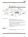
Figure 1 shows a sample network. Your Router becomes your connection to the
Internet.
FIGURE 1. Sample Home Network
ROUTER ADVANTAGES
The advantages of the Router include:
Shared Internet connection for both wired and wireless computers
High speed 802.11b/g/n wireless networking with dual radio access
No need for a dedicated, “always on” computer serving as your Internet con-
nection
Cross-platform operation for compatibility with Microsoft® Windows and Ap-
ple® MAC computers (see Technical description for supported platforms).
Easy-to-use, Web-based setup and configuration
Centralization of all network address settings (DHCP)
a Virtual server to enable remote access to Web, FTP and other services on
your network
a Security - Firewall protection - against Internet hacker attacks and encryp-
tion to protect wireless network traffic
A multi-language GUI.
MINIMUM SYSTEM AND
COMPONENT
REQUIREMENTS
Your Router requires the computer(s) and components in your network to be
configured with at least the following:

DB 6520
© (2014) ADB Broadband S.p.A. All Rights Reserved. Proprietary Use Pursuant to Cover Page Instructions.
6 Introduction
A computer with the Operating Systems that support TCP/IP networking pro-
tocols: Microsoft® Windows 98SE, Windows ME, Windows 2000, Windows
XP 32bit, Windows Vista, Windows 7, or Apple® MAC 10.x
An Ethernet 10Mbps or 10/100 Mbps NIC for each computer to be connect-
ed to one of the four Ethernet ports on the rear of the Router
As optional, an 802.11b/g wireless NIC
Supported Browsers: Internet Explorer, Netscape, Firefox, Chrome, Safari
and Opera.
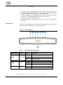
FRONT PANEL
The front panel of the Router contains indicator lights (LEDs) that help to de-
scribe the state of networking and connection operations.
FIGURE 2. Front Panel LEDs
TABLE 2. Front Panel LEDs explanation
LED Position
Color
Status
Description
Power
Green/Red
Solid Green
Power on
Light off
Power off
Solid red
Power on self-test /Device Malfunction (not bootable)
and device malfunction
HCNA
Green
Solid Light
Device connected to LAN port
Blinking
LAN Activity present
Light off
No Activity
USB
Green
Solid Green
USB Link established
Blinking Green
USB activity present (traffic in either direction)

DB 6520
© (2014) ADB Broadband S.p.A. All Rights Reserved. Proprietary Use Pursuant to Cover Page Instructions.
Introduction 7
Light off
No USB Link established
Wi-Fi / WPS
(button/LED)
Green /
Red
Solid Green
Wi-Fi
Wireless is activated on modem. OR
WPS
Successful PC synchronization: after the
blinking phase it turns solid and keep this state for 10
sec.
Solid Red
WPS
WPS failed
Blinking
Wi-Fi
Wireless activity is present
WPS
Attempting PC synchronization
Light off
Wi-Fi
Wireless off or no device attached
WPS
WPS not started
WAN Eth
Green
Solid Light
IP connected and no traffic detected
Blinking
IP connected and Internet traffic detected
Light off
Modem power off, modem in bridged mode or DSL
connection not present
DSL
Green
Solid Light
DSL good sync.
Blinking
DSL attempting sync.
Light off
No carrier signal
Internet
Green/Red
Solid Green
IP connected and no traffic detected
Solid Red
Authentication failed
Blinking Green
IP connected and Internet traffic detected
ETH1-4
Green
Solid Light
Device connected to LAN port
Blinking
LAN Activity present
Light off
No Activity
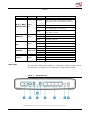
REAR PANEL
The rear panel of the Router contains a reset button, a power adapter socket,
five LAN ports, one HCNA port, two VDSL port, and two USB Host ports.
FIGURE 3. Rear Panel Ports

DB 6520
© (2014) ADB Broadband S.p.A. All Rights Reserved. Proprietary Use Pursuant to Cover Page Instructions.
8 Introduction
TABLE 3. Port Description
PORT
DESCRIPTION
A
2x Phone DSL connector (VDSL)
B
HCNA port
C
Two USB Host ports
D
Reset to factory
E
One Ethernet WAN port 10/100/1000 Mbps
F
Four Ethernet LAN ports 10/100/1000 Mbps
G
Power On/Off button
H
Power socket

© (2014) ADB Broadband S.p.A. All Rights Reserved. Proprietary Use Pursuant to Cover Page Instructions.
Router Installation 10
Router Installation
Router
Installation
INTRODUCTION
This chapter will guide you through a basic installation of the Router including:
1. Positioning the DB 6520
2. Installing Micro Filters
3. Connecting the Router to your network
4. Setting up your computer for networking with the Router
Please read carefully the Safety Information in Appendix “A”
POSITIONING THE ROUTER
You should place the Router in such a location to ensure that:
It is located near an electrical outlet and a phone wall socket
Water or moisture cannot enter the case of the unit
It is out of direct sunlight and away from sources of heat
The cabling is away from power lines, fluorescent lighting fixtures, and
sources of electrical noise such as radios, transmitters and broadband am-
plifiers.
It is centrally located with respect to the wireless devices that will be con-
nected to the Router. A suitable location might be on top of a high shelf to
ensure the maximum coverage for all connected devices.

DB 6520
© (2014) ADB Broadband S.p.A. All Rights Reserved. Proprietary Use Pursuant to Cover Page Instructions.
Router Installation 11
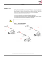
INSTALLING MICRO
FILTERS
Before beginning installation you must locate devices in your house requiring a
DSL filter such as phones, fax machines, answering machines, dial-up mo-
dems, Satellite TV dialers or monitored security systems and attach a DSL filter
to any one of them sharing the same phone line as your DSL modem.
To install DSL filters please follow these steps:
1. Disconnect the phone cable from the telephone wall socket
2. Insert the phone cable into the DSL filter port identified with a phone symbol
3. Insert the DSL filter cable into the telephone wall socket
You do not need to attach a DSL filter to unused wall sockets.
FIGURE 1. Micro Filter Installation
1
3
2

DB 6520
© (2014) ADB Broadband S.p.A. All Rights Reserved. Proprietary Use Pursuant to Cover Page Instructions.
12 Router Installation
POWERING UP THE
ROUTER
To power up the Router:
1. Plug the power adapter into the power adapter port located on the rear of
the Router
2. Plug the power adapter into a standard electrical wall socket
3. Press the Power button located on the rear panel of the Router
4. Wait for the power LED to turn steady green
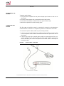
CONNECTING THE
ROUTER
The first step to install the router is to physically connect it to the telephone
socket and then connect it to a computer by means of an Ethernet connection.
To connect the phone cables (valid only for bonding models):
1. Connect one end of the first phone cable into the DSL filter port; the other
end of the phone cable shall be inserted into the first DSL port on the rear of
the Router.
2. Connect one end of the second phone cable into second phone line con-
nector available on the wall; the other end of the cable shall be connected to
the second DSL port on the rear panel of the router. (this is valid only for
bonded models)
FIGURE 2. Phone Cables Connection

DB 6520
© (2014) ADB Broadband S.p.A. All Rights Reserved. Proprietary Use Pursuant to Cover Page Instructions.
Router Installation 13
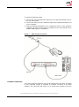
To connect the Ethernet cable:
1. Connect one end of the Ethernet cable into one of the four Ethernet ports on
the rear of the Router
2. Connect the other end of the Ethernet cable into the Ethernet Network card
of your computer
3. Verify if the Ethernet Network card is configured as DHCP client, otherwise
configure it to remain in the same local network of the router interface (see
chapter “Setting Up Your Computer”)
FIGURE 3. Ethernet Cable Connection
ETHERNET CONNECTION
You have to verify the existence of a TCP/IP protocol stack and, then, according
to your Operating System, to establish an Ethernet connection to the Data
Gateway. This connection will require you to enable your computer to receive

DB 6520
© (2014) ADB Broadband S.p.A. All Rights Reserved. Proprietary Use Pursuant to Cover Page Instructions.
14 Router Installation
from the Data Gateway its own IP Address automatically: in such a case, the
Data Gateway acts like the DHCP server in your local network.
TCP/IP CONFIGURATION
To access the Internet through the Data Gateway, you must configure the net-
work settings of the computers on your LAN to use the same IP subnet as Data
Gateway. The default IP settings for the Data Gateway are:
IP ADDRESS: 192.168.1.1
SUBNET MASK: 255.255.255.0
These settings can be changed to fit your network requirements, but you must
first configure at least one computer to access the Data Gateway's web configu-
ration interface in order to make the required changes.
ETHERNET CONNECTION
>> TCP/IP PROTOCOL
INSTALLATION
This procedure requires the TCP/IP protocol installed on your computer. Refer
to the following paragraphs and to your Windows and MacOS operating sys-
tems manuals.
Microsoft Windows Vista / Windows 7
TCP/IP stack is considered a core component of the operating system, so it
cannot be installed or uninstalled. You must check in this case that Internet Pro-
tocol (TCP/IP) is enabled. To do so, follow these steps:
1. Starting from Start -> Control Panel -> Network & Internet -> Network Con-
nections depending on the configuration of your computer.
2. Select the Network Adapter icon and from the contextual menu, do select the
Properties item.
3. In the General TAB panel, verify that Internet Protocol v4 (TCP/IPv4) item is
checked; if not, do check it and click on the OK button.
Microsoft Windows XP
TCP/IP stack is considered a core component of the operating system, so it
cannot be installed or uninstalled. You must check in this case that Internet Pro-
tocol (TCP/IP) is enabled. To do so, follow these steps:
1. Starting from Start -> Settings -> Control Panel or Start -> Control Panel de-
pending on the configuration of your computer.
2. Make a double click on the Network Connections icon.
3. Select the Network Adapter icon and from the contextual menu, do select the
Properties item.
4. In the General TAB panel, verify that Internet Protocol (TCP/IP) item is
checked; if not, do check it and click on the OK button.

DB 6520
© (2014) ADB Broadband S.p.A. All Rights Reserved. Proprietary Use Pursuant to Cover Page Instructions.
Router Installation 15
Microsoft Windows 98SE, ME, 2000
1. Insert your Windows installation CD-ROM into the CD-ROM drive.
2. Starting from Start -> Settings -> Control Panel or Start -> Control Panel de-
pending on the configuration of your computer.
3. Make a double click on the Network and Dial-up Connections icon.
4. Select the interested Network Adapter icon and from the contextual menu, do
select the Properties item.
5. If the Internet Protocol (TCP/IP) component is not checked you must enable
it by checking the Internet Protocol (TCP/IP) item; otherwise, if it is not listed,
you must install it by selecting the Install... button.
6. Choose the Protocol Network component and click on the add button.
7. In the Select Network Protocol panel, do choose Internet Protocol (TCP/IP)
and the OK button.
8. After rebooting, you're ready to configure the TCP/IP setting, as described in
the following paragraphs.
Apple MacOS 10.x
TCP/IP is installed on a MacOS system as part of Open Transport.
ETHERNET CONNECTION
>> MS WINDOWS VISTA /
WINDOWS 7
To configure TCP/IP on MS Windows Vista / Windows 7 Operating Systems fol-
low these steps:
1. Select Start -> Control Panel -> Network & Internet and make a double click
on the Network Connections icon.
2. Select the adapter card interested by TCP/IP configuration.
3. Select the Properties item from the contextual Adapter Card menu.
4. Select in the General TAB panel, the Internet Protocol (TCP/IPv4) item and
then click on Properties button.
5. In the General TAB panel, check the Obtain an IP address automatically radio
button and the Obtain DNS server address automatically radio button. Click
on OK button.
ETHERNET CONNECTION
>> MS WINDOWS XP
To configure TCP/IP on MS Windows XP Operating System follow these steps:
1. Select Start -> Settings -> Control Panel and make a double click on the Net-
work Connections icon.
2. Select the adapter card interested by TCP/IP configuration.
3. Select the Properties item from the contextual Adapter Card menu.
4. Select in the General TAB panel, the Internet Protocol (TCP/IP) item and then
click on Properties button.

DB 6520
© (2014) ADB Broadband S.p.A. All Rights Reserved. Proprietary Use Pursuant to Cover Page Instructions.
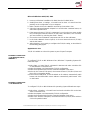
16 Router Installation
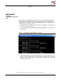
FIGURE 4. Local Area Connection Properties
5. In the General TAB panel, check the Obtain an IP address automatically radio
button and the Obtain DNS server address automatically radio button. Click
on OK button.
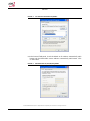
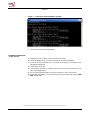
FIGURE 5. Internet Protocol (TCP/IP) Properties

DB 6520
© (2014) ADB Broadband S.p.A. All Rights Reserved. Proprietary Use Pursuant to Cover Page Instructions.
Router Installation 17
ETHERNET CONNECTION
>> MS WINDOWS 98SE, ME,
2000
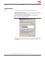
To configure TCP/IP on these Operating Systems follow these steps:
1. Select Start -> Settings -> Control Panel and make a double click on the Net-
work and Dial-up Connection icon.
2. Select the adapter card interested by TCP/IP configuration and then select
the Properties item from its contextual menu.
3. Select Internet Protocol (TCP/IP) item then click on Properties button.
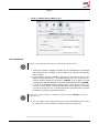
FIGURE 6. Local Area Connection Properties
1. Select the General TAB panel, then check the Obtain an IP address auto-
matically and Obtain DNS server address automatically radio buttons. Click
on OK button.
Page is loading ...
Page is loading ...
Page is loading ...
Page is loading ...
Page is loading ...
Page is loading ...
Page is loading ...
Page is loading ...
Page is loading ...
Page is loading ...
Page is loading ...
Page is loading ...
Page is loading ...
Page is loading ...
Page is loading ...
Page is loading ...
Page is loading ...
Page is loading ...
-
 1
1
-
 2
2
-
 3
3
-
 4
4
-
 5
5
-
 6
6
-
 7
7
-
 8
8
-
 9
9
-
 10
10
-
 11
11
-
 12
12
-
 13
13
-
 14
14
-
 15
15
-
 16
16
-
 17
17
-
 18
18
-
 19
19
-
 20
20
-
 21
21
-
 22
22
-
 23
23
-
 24
24
-
 25
25
-
 26
26
-
 27
27
-
 28
28
-
 29
29
-
 30
30
-
 31
31
-
 32
32
-
 33
33
-
 34
34
-
 35
35
-
 36
36
-
 37
37
-
 38
38


HON HAI PRECISION IND. DB 6520 User manual
- Category
- Routers
- Type
- User manual
Ask a question and I''ll find the answer in the document
Finding information in a document is now easier with AI

