Page is loading ...

METRA. THE WORLD’S BEST KITS.™
© COPYRIGHT 2004-2011 METRA ELECTRONICS CORPORATION
APPLICATIONS
1-800-221-0932
metraonline.com
INSTALLATION INSTRUCTIONS FOR PART 99-2022
REV. 7/16/2012 INST99-2022
WIRING & ANTENNA CONNECTIONS
Wiring Harness: • GMOS-044 and ASWC-steering wheel interface included!
Antenna Adapter: • 40-EU55 - amplified antenna adapter (Sold separately)
Panel Removal Tool • Phillips Screwdriver • Socket Wrench
TOOLS REQUIRED
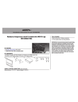
Buick Regal 2011-up
(Not designed for NAV equipped vehicles)
99-2022B, 99-2022BR
B C D
E
A
•
A) Radio Trim Panel
•
B) Radio Brackets
•
C) Pocket
•
D) Climate Control Trim Ring
•
E) Climate Control Trim Panel
•
F) Data Interface
•
G) ASWC Interface
•
H) Interface Harness
•
I) (2) #8 x 3/8” Pan-head Phillips screws
•
J) (4) #8 x 3/8” Truss-head Phillips screws
•
K) Switch Blank Plate
KIT FEATURES
KIT COMPONENTS
• ISO DIN Head unit provision with pocket
• DDIN Head unit provisions
• Painted Black to match factory finish
• Painted Brown to match factory finish
F
H
I
K
G
J

Table of Contents
Dash Disassembly
– Buick Regal 2011-up 3-4
Kit Assembly
– Radio panel assembly 5
– Climate control panel assembly 6
– ISO DIN head unit provisions 7
– DDIN head unit provisions 8
Interface Installation
– Interface Installation 9-12
KNOWLEDGE IS POWER
Enhance your installation and fabrication skills by
enrolling in the most recognized and respected
mobile electronics school in our industry.
Log onto www.installerinstitute.com or call
800-354-6782 for more information and take steps
toward a better tomorrow.
Metra recommends MECP
certified technicians
99-2022
Caution
Metra recommends disconnecting the negative battery terminal before beginning any
installation. All accessories, switches, and especially air bag indicator lights must be
plugged in before reconnecting the battery or cycling the ignition.
*NOTE: Refer also to the instructions included with the aftermarket radio.

1. Unsnap and remove the pocket/ashtray
assembly. (Figure A)
2. Unsnap and remove the trim above the
glove box. (Figure B)
3. Unsnap and remove the trim between
the radio and steering wheel. (Figure C)
Continued on next page
3
Dash Disassembly
99-2022
(Figure A)
(Figure B)
(Figure C)

4
99-2022
Dash Disassembly
(Figure D)
(Figure E)
(Figure F)
4. Unsnap and remove the vent/ screen
panel above the radio. (take caution
not to cycle the key with this panel
unplugged) (Figure D)
5. Remove four 7 mm screws to remove
radio face and climate controls.
(Figure E)
6. Remove four 7 mm screws to remove
the radio chassis. (Figure F)
Continue to kit assembly

5
Kit Assembly 99-2022
Radio Panel Assembly
(Figure A)
1. Unsnap the climate controls, traction
control switch, park assist switch and
start/stop switch (if equipped) from the
factory radio panel. (Figure A)
2. Snap the switches into the Metra kit
panel. Note: If no start/stop switch
is present use the supplied switch
blank plate.
Continued on next page
Climate Controls
Parking Assist switch Traction Control switch Start/Stop switch

Kit Assembly 99-2022
6
3. Snap the climate control in the climate
control panel. Note: Minor sub dash
modification may be necessary to
allow for clearance of the climate
control (See inset). (Figure B)
Continued on next page
Climate Control Panel Assembly
(Figure B)
Climate control
trim ring
Climate controls
Climate control
trim panel
Shaded areas indicated may
need minor clearancing.

Kit Assembly 99-2022
7
ISO DIN head unit provision with pocket
1. Mount the radio to the brackets with the
screws included with unit. (Figure A)
2. Mount the pocket to the radio brackets
with the screws supplied. (Figure A)
3. Locate the factory wiring harness
and antenna plug in the dash. Metra
recommends using the proper mating
adapters from Metra and/or AXXESS.
4. Mount assembly into the sub dash.
(Figure B)
5. Reassemble dash in reverse order of
disassembly using 99-2022 trim
panel instead of factory panel.
Continue to Interface Installation
(Figure A)
(Figure B)

Kit Assembly 99-2022
8
Double DIN head unit provisions
1. Mount the radio to the DDIN brackets
with screws included with unit.
(Figure A)
2. Locate the factory wiring harness
and antenna plug in the dash. Metra
recommends using the proper mating
adapters from Metra and/or AXXESS.
3. Mount assembly into the sub dash.
(Figure B)
4. Reassemble dash in reverse order of
disassembly using 99-2022 trim panel
instead of factory panel.
Continue to Interface Installation
(Figure A)
(Figure B)

99-2022
9
Interface Installation
*Important: Before beginning any of
the following, disconnect the negative
battery terminal to prevent an accidental
short circuit.
The included interface with this kit is
designed to retain Onstar, and retain factory
warning chimes, and keep the factory
climate display active. It also provides a
12-volt accessory output, mute, park brake,
speed signal and reverse output.
Interface Components
Tools required for installation
IGNITION
TERMINALS
WIRE
CUTTER
M3.5
M2.6
M3
M5
M4
ISO
6
2.5
1.5
• Cutting Tool • Tape • Crimping Tool • Connectors (I.E. butt-connectors, bell caps, ECT…)
• Female Spade Connectors (Optional)
• A) Interface • B) Harness
A
B

99-2022
10
Interface Installation
*Important: Before beginning any of the following, disconnect the negative battery
terminal to prevent an accidental short circuit.
1. From the 16-way harness:
• Connect the red wire to the ignition/accessory wire of the aftermarket radio
• Connect the Orange/White wire to the illumination wire of the aftermarket radio. If the
aftermarket radio has no illumination wire just tape off the Orange/White wire.
• Connect the blue/white wire to the amp turn on wire of the aftermarket radio.
• Connect the white wire to the left front positive speaker output of the aftermarket radio
• Connect the white/black wire to the left front negative speaker output of the
aftermarket radio
• Connect the gray wire to the right front positive speaker output of the aftermarket radio
• Connect the gray/black wire to the right front negative speaker output of the
aftermarket radio
• Connect the green wire to the left rear positive speaker output of the aftermarket radio
• Connect the green/black wire to the left rear negative speaker output of the
aftermarket radio
• Connect the purple wire to the right rear positive speaker output of the aftermarket radio
• Connect the purple/black wire to the right rear negative output of the aftermarket radio
• Connect the Brown wire to the mute wire of the aftermarket radio. If the aftermarket
radio does not have a Mute wire, tape up the Brown wire.
The following wires on the 16-pin harness are for the aftermarket radios
that have navigation built in:
• Connect the Light Green wire to the parking brake wire of the aftermarket
navigation radio.
• Connect the Blue/Pink wire to the VSS or speed sense wire of the aftermarket
navigation radio.
• Connect the Green/Purple wire to the reverse wire of the aftermarket navigation radio.
Continued on next page

99-2022
11
Interface Installation
2. From the 44-way harness:
• Connect the Yellow wire to the 12-volt constant/battery wire of the aftermarket radio
• Connect the Black wire to the ground wire of the aftermarket radio
• Connect the RCA’s to the AUX input of your aftermarket radio.
3. From the 18-way harness:
• Connect the Black wire with the ring terminal to the radio chassis.
(This wire must be grounded here by itself for the interface to work properly)
• The Black/Yellow wire and additional 12-pin harness will be discussed
later in this manual
• Connect the RCA’s to the AUX input of your aftermarket radio (if equipped)
Chime Volume Adjustment
To adjust the chime volume, use a small screwdriver to rotate the potentiometer, located
on the 16-pin harness side of the interface, clockwise to make the chime louder and
counterclockwise to make the chime softer.
Onstar Level Adjustment
To adjust the Onstar volume level find the Black/Yellow wire on the 22-pin harness.
Push the blue Onstar button, while the voice is speaking tap the Black/Yellow wire to
ground. There are 4 volume settings for Onstar; once the 4th setting is reached and the
Black/Yellow wire is tapped to ground it will automatically go back to the first volume
setting. Once the volume is set it will stay at that volume until the Black/Yellow wire is
tapped to ground again.
This can be set during installation and then left alone.
If user adjustment is desired, the customer may also tap volume up or down to
adjust the Onstar level.
Continued on next page

99-2022
12
Interface Installation
12-Pin Harness
1. Plug the 12-pin harness into the ASWC interface box.
2. Plug 3.5 mm into aftermarket radio.
3. Tap Volume Up continuously until LED stops flashing rapidly on first initialization
of ASWC to program.
Note: Please refer to the www.axxessinterface.com for custom
button remapping instructions.
Testing the Interface
1. Turn the ignition on, and then turn the aftermarket radio on.
2. Push the Onstar button, the radio should turn off and you should hear Onstar.
Push the Onstar cancel button and the radio should come back on.
Personalization Menu
Note: Vehicle must have steering wheel controls from the factory
1. Turn off your aftermarket radio.
2. Press and hold off hook for 3 seconds. After 3 seconds the personalization menu will
show up on the display.
3. To scroll through the menu’s use seek up and down
4. To make a selection, use the Source button which is the center button between
seek up and down.
5. Use off hook to exit the personalization menu
Note: Personalization menu can be set before the factory radio is removed.

METRA. THE WORLD’S BEST KITS.™
© COPYRIGHT 2004-2011 METRA ELECTRONICS CORPORATION
1-800-221-0932
metraonline.com
INSTALLATION INSTRUCTIONS FOR PART 99-2022
REV. 7/16/2012 INST99-2022

METRA. THE WORLD’S BEST KITS.™
© COPYRIGHT 2004-2011 METRA ELECTRONICS CORPORATION
1-800-221-0932
metraonline.com
INSTRUCCIONES DE INSTALACIÓN PARA LA PIEZA 99-2022B
REV. 7/16/2012 INST99-2022
/