Page is loading ...

PDUNV
Universal Rackmount
Power Distribution Unit (PDU)
Owner’s Manual
1111 W. 35th Street • Chicago, IL 60609 USA
(773) 869-1234 • www.tripplite.com
Important Safety Instructions
SAVE THESE INSTRUCTIONS
This manual contains instructions and warnings that should be followed
during the installation, operation, and storage of this product. Failure to
heed these instructions and warnings will void the product warranty.
Important Warnings
• The PDU provides convenient multiple outlets, but it DOES NOT provide surge or line noise protection for
connected equipment.
• The PDU is designed for indoor use only in a controlled environment away from excess moisture, temperature
extremes, conductive contaminants, dust or direct sunlight.
• Do not connect the PDU to an ungrounded outlet or to extension cords or adapters that eliminate
the connection to ground.
• The power requirement for each piece of equipment connected to the PDU must not exceed the individual
outlet’s load rating.
• The total power requirement for equipment connected to the PDU must not exceed the maximum load
rating for the PDU.
• Do not drill into or attempt to open any part of the PDU housing. There are no user-serviceable parts inside.
• Do not attempt to modify the PDU, including the input plugs and power cables.
• Do not attempt to use the PDU if any part of it becomes damaged.
• Do not attempt to mount the PDU to an insecure or unstable surface.
• Never attempt to install electrical equipment during a thunderstorm.
Installation
Step 1: Determine Installation Configuration. The PDU supports four primary installation configurations: 1U
Rack, 0U Rack, Wall and Under-Counter. Choose a configuration and follow the installation instructions in the
appropriate section of Step 1 before proceeding to Step 2.
Note: Regardless of installation configuration, the user must determine the fitness of hardware and procedures
before mounting. The PDU and included hardware are designed for common rack and rack enclosure types and
may not be appropriate for all applications. Exact mounting configurations may vary.
Step 1-1: 1U Rack Installation. Attach the PDU to the rack by inserting four user-supplied screws (A) through
the PDU mounting brackets (B) and into the mounting holes of the rack rail as shown.
Step 1-2: 0U Rack Installation. Part 1: Remove the screws (C) attaching the mounting brackets to the PDU,
change the orientation of the brackets as shown and reattach the brackets. Use only the screws supplied by the
manufacturer or their exact equivalent (#6-32, 1/4” flat head). Part 2: Attach the PDU vertically by inserting two
or more user-supplied screws (A) through the PDU mounting brackets (B) and into mounting points in the rack
or rack enclosure.
Step 1-3: Wall Installation. After repeating Part 1 above, attach the PDU to a stable mounting surface by
inserting two or more user-supplied screws (A) through the PDU mounting brackets (B) and into secure
mounting points on the mounting surface.
Step 1-4: Under-Counter Installation. After repeating Part 1 above, attach the PDU to a stable mounting
surface by inserting four user-supplied screws (A) through the PDU mounting brackets (B) and into secure
mounting points on the mounting surface.
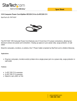
Step 2: Connect PDU to Grounded Outlet. The PDU includes several plug
adapters which allow the PDU to connect to various outlet types. After choosing the
appropriate plug adapter for the required application, insert the IEC-320-C19
connector (D) of the adapter into the IEC-320-C20 connector (E) of the input cable.
Secure the connection with the Cord Retention Bracket (F) by using the included
bolts to fasten the two halves of the bracket around the connection as shown. Insert
the plug directly into a properly grounded AC outlet that does not share a circuit
with a heavy electrical load (such as an air conditioner or refrigerator). Caution: The Line (L1) conductor includes
an over-current protective device for safety. To avoid the risk of electric shock, ensure that the Neutral (L2)
conductor has been identified before connecting the PDU.
1-1
IEC-320-C19 Outlets
IEC-320-C13 Outlets
Circuit Breaker: If the current drawn by the
equipment connected to the PDU exceeds the
Maximum Load Rating for longer than a few
seconds, the circuit breaker will activate and interrupt
AC power to prevent possible damage. When the
circuit breaker activates, its plunger will pop up.
Disconnect excess equipment from the PDU and
allow the breaker to cool one minute before
depressing the plunger to reset the breaker.
NEMA 5-15P connects to NEMA 5-15R outlet.
NEMA 5-20P connects to NEMA 5-20R outlet.
NEMA L5-20P connects to NEMA L5-20R outlet.
NEMA L6-20P connects to NEMA L6-20R outlet.
IEC-320-C14 connects to user-supplied power
cord with IEC-320-C13 or to a UPS/power supply.
IEC-320-C20 connects to user-supplied power
cord with IEC-320-C19, to an input adapter or to a
UPS/power supply.
Limited Lifetime Warranty
Seller warrants this product, if used in accordance with all applicable instructions, to be free from original
defects in material and workmanship for its lifetime. If the product should prove defective in material or
workmanship within that period, Seller will repair or replace the product, at its sole discretion. Service under this
Warranty can only be obtained by Buyer delivering or shipping the product (with all shipping or delivery charges
prepaid) to: Tripp Lite, 1111 W. 35th Street, Chicago, IL 60609. Seller will pay return shipping charges. Call
Tripp Lite at (773) 869-1234 before sending any equipment back for repair.
THIS WARRANTY DOES NOT APPLY TO NORMAL WEAR OR TO DAMAGE RESULTING FROM
ACCIDENT, MISUSE, ABUSE OR NEGLECT. SELLER MAKES NO EXPRESS WARRANTIES OTHER
THAN THE WARRANTY EXPRESSLY SET FORTH HEREIN. EXCEPT TO THE EXTENT PROHIBITED
BY APPLICABLE LAW, ALL IMPLIED WARRANTIES, INCLUDING ALL WARRANTIES OF
MERCHANTABILITY OR FITNESS, ARE LIMITED IN DURATION TO THE WARRANTY PERIOD SET
FORTH ABOVE; THIS WARRANTY EXPRESSLY EXCLUDES ALL INCIDENTAL AND
CONSEQUENTIAL DAMAGES. (Some states do not allow limitations on how long an implied warranty lasts,
and some states do not allow the exclusion or limitation of incidental or consequential damages, so the above
limitations or exclusions may not apply to you. This Warranty gives you specific legal rights, and you may have
other rights which vary from jurisdiction to jurisdiction).
WARNING: The individual user should take care to determine prior to use whether this device is suitable,
adequate or safe for the use intended. Since individual applications are subject to great variation, the
manufacturer makes no representation or warranty as to the suitability or fitness of these devices for any specific
application.
The policy of Tripp Lite is one of continuous improvement. Specifications are subject to change without notice.
WARRANTY REGISTRATION
Visit www.tripplite.com/warranty today to register the warranty for your new Tripp Lite product. You'll be automatically entered
into a drawing for a chance to win a FREE Tripp Lite product!*
* No purchase necessary. Void where prohibited. Some restrictions apply. See website for details.
Regulatory Compliance Identification Numbers
For the purpose of regulatory compliance certifications and identification, your Tripp Lite product has been assigned a unique
series number. The series number can be found on the product nameplate label, along with all required approval markings and
information. When requesting compliance information for this product, always refer to the series number. The series number
should not be confused with the marking name or model number of the product.
This product designed and engineered in the USA.
Copyright © 2006 Tripp Lite. All rights reserved.
A
B
C
D
Warranty
Registration
Register online today for a chance
to win a FREE Tripp Lite product!
www.tripplite.com/warranty
PDUNV
Montaje en bastidor
Unidad universal de distribución de potencia (PDU)
Manual del propietario
1111 W. 35th Street • Chicago, IL 60609 USA
(773) 869-1234 • www.tripplite.com
Instrucciones de seguridad importantes
GUARDE ESTAS INSTRUCCIONES
Este manual contiene instrucciones y advertencias que deben seguirse
durante la instalación, operación y almacenamiento de este producto. De
no seguirlas, se anulará la garantía del producto.
Advertencias importantes
• La PDU proporciona cómodas salidas múltiples, pero NO proporciona protección contra sobretensión o ruido
en la línea al equipo conectado.
• La PDU está diseñada sólo para empleo en interiores en un ambiente controlado, lejos del exceso de humedad,
temperaturas extremas, contaminantes conductores, polvo o luz solar directa.
• No conecte la PDU a una salida sin conexión a tierra ni a cables de extensión o adaptadores que eliminen la
conexión a tierra.
• El requisito de potencia de cada equipo conectado a la PDU no debe exceder la capacidad de carga individual
de la salida.
• El requisito de potencia total para el equipo conectado la PDU no debe exceder la máxima capacidad de carga
para la PDU.
• No taladre ni trate de abrir ninguna parte de la cubierta de la PDU. No hay partes en su interior que requieran
mantenimiento por parte del usuario.
• No intente modificar la PDU, incluyendo los enchufes de entrada y los cables de alimentación.
• No intente usar la PDU si alguno de sus componentes está dañado.
• No intente montar la PDU en una superficie insegura o inestable.
• Nunca intente instalar equipos eléctricos durante una tormenta eléctrica.
1-2
1-3
1-4
A
B
B
A
C
A
B
C
B
C
A
C
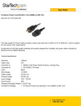
Step 3: Connect Equipment to PDU. Connect equipment to the
PDU with user-supplied IEC-320 interconnection cords. Be careful
not to exceed the load rating for each outlet nor the total load rating
for the PDU. Note: Interconnection cords (IEC-320-C13 to IEC-
320-C14) are available from Tripp Lite. Call 773-869-1234 (Part #
P004-006).
Step 4: Optional Installation (Not Shown). The input power
cord’s IEC-320-C20 connector and the IEC-320-C14 adapter can
each connect to user-supplied power cords with plugs appropriate for the installation site’s utility outlets. This
capability is useful for connecting the PDU to various international outlet types.
Installation (continued)
E F G
H I
Paso 1: Determine la configuración de la instalación. La PDU soporta cuatro configuraciones básicas de
instalación: Bastidor de 1U, bastidor de 0U, de pared y debajo de mostrador. Elija una configuración y siga las
instrucciones de instalación en la sección apropiada del Paso 1 antes de continuar al Paso 2. Nota:
Independientemente de la configuración, el usuario debe determinar la idoneidad de los materiales y accesorios
así como de los procedimientos antes del montaje. La PDU y el material incluido están diseñados para racks
(bastidores) y cajas de rack (bastidor) comunes, y pueden no ser apropiados para todas las aplicaciones.
Paso 1-1: Instalación en bastidor de 1U. Fije la PDU al bastidor insertando cuatro tornillos suministrados por
el usuario (A) a través de los soportes de montaje (B) de la PDU en los agujeros de montaje del riel del bastidor
como se muestra.
Paso 1-2: Instalación en bastidor de 0U. Parte 1: Retire los tornillos (C) que fijan los soportes de montaje a la
PDU, cambie la orientación de los soportes como se muestra y fíjelos nuevamente. Use solo los tornillos
incluidos o sus equivalentes exactos (#6-32, 1/4" de cabeza plana). Parte 2: Fije la PDU verticalmente insertando
dos o más tornillos suministrados por el usuario (A) a través de los soportes de montaje (B) de la PDU en los
puntos de montaje en el bastidor o la caja del bastidor.
1-1
1-2
1-3
1-4
A
B
B
A
C
A
B
C
B
C
A
C
Instalación
D
2
3
A
B
C
D
E
F
G
H
I
Features
INPUT PLUG ADAPTERS
E
F
200603146 93-2537 Rackmount PDU.qxd 4/19/2006 11:32 AM Page 1
/