1
Replacement Transmitter Antenna Assembly
Manual for the DX6i
NOTICE
All instructions, warranties and other collateral documents are subject to change
at the sole discretion of Horizon Hobby, Inc. For up-to-date product literature, visit
http://www.horizonhobby.com and click on the support tab for this product.
WARNING: READ AND FOLLOW ALL INSTRUCTIONS
This manual contains instructions for safely replacing a transmitter antenna. This
replacement antenna is a key component in a sophisticated hobby product. The
instructions require basic technical knowledge and mechanical skill. The replace-
ment should not be attempted by children or beginner hobbyists.
Do not attempt disassembly, use with incompatible components, or augment the
product in any way, outside of these instructions. Failure to follow each instruc-
tion and precaution could result in a break of signal transmission, which will
ultimately lead to damage to the product, property and/or personal injury.
Read ALL instructions. If after reading these instructions you are not confident
in your ability to replace the antenna, send the antenna and transmitter to the
appropriate Horizon Service Center where this procedure can be performed by
an authorized service technician free of charge, or contact a distributor in your
country of service.
To obtain free repair service for your Replacement Transmitter Antenna Assembly
please contact Horizon Hobby Product Support.
Note: If it is decided to submit the unit for antenna replacement, Horizon will pay the
costs of return shipping and labor associated with the replacement of the antenna.
However the cost to repair any OTHER damage done to the product may be the
responsibility of the customer, to be determined at the sole discretion of Horizon
Hobby, Inc.
INTRODUCTION
The following instructions are for replacing the antenna in a DX6i. Read them com-
pletely before beginning to replace your antenna.
Items Needed:
• New antenna assembly (SPM6830)
• Medium Phillips head screwdriver
CAUTION: Never turn the radio on when the antenna is not attached to the
module. Powering up the transmitter without the antenna attached can damage
the transmitter.
STEP 1
With the transmitter power switch in the “Off” position, remove the battery door and
the batteries from the transmitter.
STEP 2
Place the radio face down on a cushioned surface to protect it from being damaged.
Using a Phillips screwdriver, remove the 6 screws holding the transmitter case
together. All removed screws should be placed in a designated area where they
will not be lost and should be placed in a manner that will allow for ordered
reinsertion.
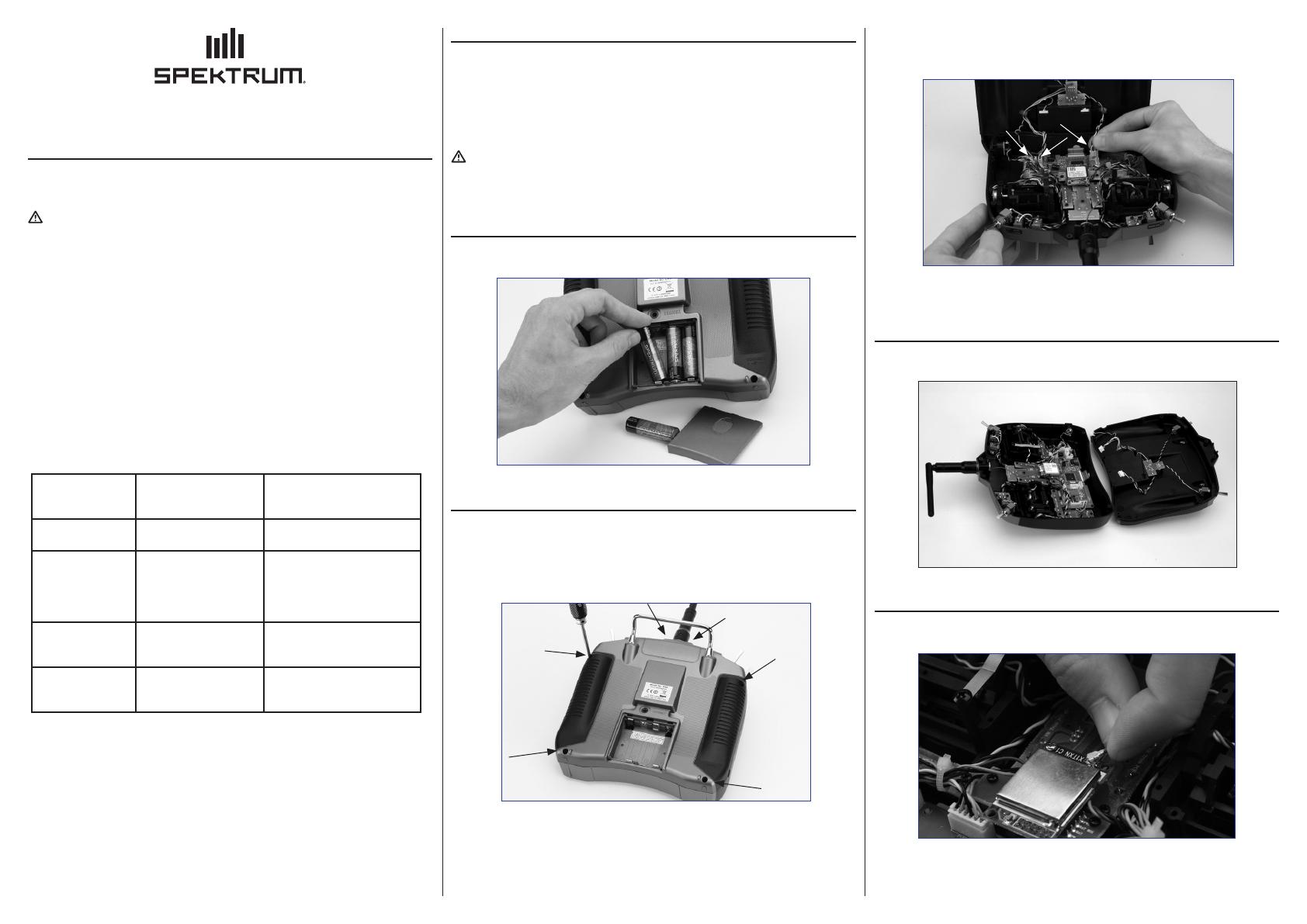
STEP 3
Carefully remove the back case half disconnecting the wire harness connectors from
the encoder board in the front case.
NOTICE: Observe the location of each plug being removed. Reinserting the plugs
incorrectly will result in damage to the radio.
STEP 4
With the wire harness connectors separated from the encoder board, lay the back
case half aside.
STEP 5
Carefully grasp the antenna wire near the connection point to the RF board and pull
up while wiggling slightly. The antenna should disconnect easily.
Horizon Service Center 4105 Fieldstone Road
Champaign, IL 61822 USA
877-504-0233
Online Repairs visit
www.horizonhobby.com/repairs/
Horizon Product
Support
4105 Fieldstone Road
Champaign, IL 61822 USA
877-504-0233
productsupport@horizonhobby.com
Horizon Hobby Limited Units 1-4 Ployters Rd
Staple Tye
Harlow, Essex
CM18 7NS
United Kingdom
+44 (0) 1279 641 097
sales@horizonhobby.co.uk
Horizon Technischer
Service
Hamburger Str. 10
25335 Elmshorn
Germany
+49 4121 46199 66
service@horizonhobby.de
Horizon Hobby SAS
14 Rue Gustave Eiffel
Zone d’Activité du Réveil Matin
91230 Montgeron
+33 (0) 1 60 47 44 70
infofrance@horizonhobby.com
WWW.SPEKTRUMRC.COM

