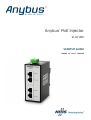
Anybus AWB4006 Quick start guide
- Category
- PoE adapters
- Type
- Quick start guide

Anybus®PoE Injector
12–57 VDC
STARTUP GUIDE
SP2385 1.3 en-US ENGLISH

Important User Information
Disclaimer
The information in this document is for informational purposes only. Please inform HMS Industrial
Networks of any inaccuracies or omissions found in this document. HMS Industrial Networks disclaims
any responsibility or liability for any errors that may appear in this document.
HMS Industrial Networks reserves the right to modify its products in line with its policy of continuous
product development. The information in this document shall therefore not be construed as a
commitment on the part of HMS Industrial Networks and is subject to change without notice. HMS
Industrial Networks makes no commitment to update or keep current the information in this document.
The data, examples and illustrations found in this document are included for illustrative purposes and are
only intended to help improve understanding of the functionality and handling of the product. In view of
the wide range of possible applications of the product, and because of the many variables and
requirements associated with any particular implementation, HMS Industrial Networks cannot assume
responsibility or liability for actual use based on the data, examples or illustrations included in this
document nor for any damages incurred during installation of the product. Those responsible for the use
of the product must acquire sufficient knowledge in order to ensure that the product is used correctly in
their specific application and that the application meets all performance and safety requirements
including any applicable laws, regulations, codes and standards. Further, HMS Industrial Networks will
under no circumstances assume liability or responsibility for any problems that may arise as a result from
the use of undocumented features or functional side effects found outside the documented scope of the
product. The effects caused by any direct or indirect use of such aspects of the product are undefined
and may include e.g. compatibility issues and stability issues.
Anybus®PoE Injector Startup Guide SP2385 1.3 en-US

About This Document 3 (12)
1 About This Document
This document describes how to install Anybus PoE Injector 12–57 VDC.
For additional documentation and technical support regarding this product,
please visit www.anybus.com/support.
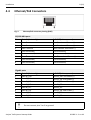
1.1 Document Conventions
The following formatting conventions are used in this document to indicate
safety information and other content of specific importance:
WARNING
This instruction must be followed to avoid a risk of death or serious injury.
Caution
This instruction must be followed to avoid a risk of personal injury.
This instruction must be followed to avoid a risk of reduced functionality
and/or damage to the equipment, or to avoid a network security risk.
This is additional information which may facilitate installation and/or operation.
Anybus®PoE Injector Startup Guide SP2385 1.3 en-US

Safety 4 (12)
2 Safety
2.1 Intended Use
The intended use of this equipment is to provide DC power over Ethernet cables.
If this equipment is used in a manner not specified by the manufacturer, the
protection provided by the equipment may be impaired.
3 Description
Anybus PoE Injector 12–57 VDC is a dual port 802.3af/at compliant Power over
Ethernet injector with Midspan Intelligent Detection.
The PoE injector will not turn on power until it detects a valid PoE signature
from the devices attached downstream on the Ethernet cable. This protects
non-compliant equipment against damage.
Anybus PoE Injector 12–57 VDC will not function with equipment that is not
fully compliant with the IEEE 802.3af/at PoE standards.
The unit requires an external 12–57 VDC power supply (not included).
Anybus®PoE Injector Startup Guide SP2385 1.3 en-US

Installation 5 (12)
4 Installation
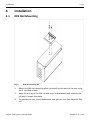
4.1 DIN Rail Mounting
Fig. 1 DIN rail mounting kit
1. Attach the DIN rail mounting plate (included) to the back of the unit using
the 3 included screws.
2. Hook the unit onto the DIN rail and press it downwards and towards the
rail until it snaps into place.
3. To remove the unit, press downwards and pull the unit free from the DIN
rail.
Anybus®PoE Injector Startup Guide SP2385 1.3 en-US

Installation 6 (12)
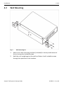
4.2 Wall Mounting
Fig. 2 Wall mounting kit
1. Attach the 2 wall mounting brackets (included) to the top and bottom of
the unit using the included screws.
2. Hold the unit upright against the wall and fasten it with suitable screws
through the apertures in the brackets.
Anybus®PoE Injector Startup Guide SP2385 1.3 en-US


Installation 8 (12)
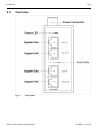
4.4 Ethernet/PoE Connectors
Fig. 4 Ethernet/PoE connector pinning (RJ45)
10/100 Mbit ports
Pin Data IN (data only) PoE OUT (data + power)
1 Data Receive Data Receive and Power (+)
2 Data Receive Data Receive and Power (+)
3 Data Transmit Data Transmit and Power (-)
4(not connected) (not connected)
5(not connected) (not connected)
6 Data Transmit Data Transmit and Power (-)
7(not connected) (not connected)
8(not connected) (not connected)
Gigabit ports
Pin Data IN (data only) PoE OUT (data + power)
1 Data BI_DA+ Data BI_DA+ and Power(+)
2 Data BI_DA- Data BI_DA- and Power(+)
3 Data BI_DB+ Data BI_DB+ and Power(-)
4 Data BI_DC+ Data BI_DC+
5 Data BI_DC- Data BI_DC-
6 Data BI_DB- Data BI_DB- and Power(-)
7 Data BI_DD+ Data BI_DD+
8 Data BI_DD- Data BI_DD-
Do not connect pins 3 or 6 to ground.
Anybus®PoE Injector Startup Guide SP2385 1.3 en-US

Installation 9 (12)
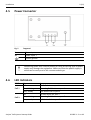
4.5 Power Connector
Fig. 5 Top panel
V- Power Input -
V+ Power Input +
Chassis ground
Connecting power with reverse polarity or using the wrong type of power
supply may damage the equipment. Make sure that the power supply is
connected correctly and of the recommended type.
4.6 LED Indicators
PWR Green Power on
PoE 1
Off No PoE device on port 1
Blue, blinking Detecting PoE device on port 1
Blue, steady PoE device link on port 1
PoE 2
Off No PoE device on port 2
Blue, blinking Detecting PoE device on port 2
Blue, steady PoE device link on port 2
Anybus®PoE Injector Startup Guide SP2385 1.3 en-US

Technical Data 10 (12)
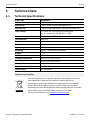
5 Technical Data
5.1 Technical Specifications
Order code AWB4006-B
PoE standard IEEE 802.3at/802.3af
Ethernet IN 2x RJ45 (Data, 10/100/1000 Base-T(x))
Ethernet OUT 2 x RJ45 (Data and power, 10/100/1000 Base-T(x))
Input voltage 12-57 VDC on 4-pin screw terminal block
For UL compliance: 24–50 VDC +/-10%
Output voltage 50 V / 600 mA, 30 W max. per port
LED indicators PWR, PoE
Short circuit protection Yes
Overload protection Yes
High voltage protection Yes
Mounting DIN rail + wall mount (included)
Weight 370g
Protection class IP30
Storage temperature -40 to 80°C (-40 to 176°F)
Operating temperature -20 to 70°C (-4 to 158°F)
Housing Metal
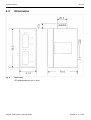
Dimensions W×H×D 41 x 95 x 70
Certifications See datasheet
Disposal and recycling
You must dispose of this product properly according to local laws
and regulations. Because this product contains electronic
components, it must be disposed of separately from household
waste. When this product reaches its end of life, contact local
authorities to learn about disposal and recycling options, or simply
drop it off at your local HMS office or return it to HMS.
For more information, see www.hms-networks.com.
Anybus®PoE Injector Startup Guide SP2385 1.3 en-US


last page
© 2019 HMS Industrial Networks
Box 4126
300 04 Halmstad, Sweden
[email protected] SP2385 1.3 en-US / 2019-05-20 / 13361
-
 1
1
-
 2
2
-
 3
3
-
 4
4
-
 5
5
-
 6
6
-
 7
7
-
 8
8
-
 9
9
-
 10
10
-
 11
11
-
 12
12


Anybus AWB4006 Quick start guide
- Category
- PoE adapters
- Type
- Quick start guide
Ask a question and I''ll find the answer in the document
Finding information in a document is now easier with AI
Related papers
-
Anybus AWB4005 Quick start guide
-
-
-
-
-
-
-
-
-
Other documents
-
HMS Anybus Wireless Bridge II Startup Manual
-
StarTech.com POEINJ2GI User manual
-
Interlogix IFS MC252-4P-1S User manual
-
-
-
-
IXXAT Modbus-TCP User guide
-
ACTi PPSW-0100 User manual
-
 MSTRONIC DIN-POE1 User manual
-
