
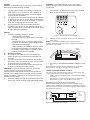
EXAMPLE CONFIGURATIONS
The following shows four example combinations of angle
and blanking settings:
Optimum Height
Figure 2: Sensor 3m high, 5 degree tilt, 30m range
6 Metres
Figure 3: Sensor 6m high, 15 degree tilt, 30m range
Pet Immunity (lower lenses blanked)
Figure 4: Sensor 1.5m high, -5 degree tilt, 30m range
Curtain Coverage (upper lenses blanked)
Figure 5: Sensor 6m high, 45 degree tilt, 5m range
INTRODUCTION
The mini Opal is an attractively styled, 30 metre Passive
Infrared (PIR) detector that works with GJD security
lighting controllers. The mini Opal has additional
advanced PIR features as follows:
• Sensor mounted white-light lter to stabilise
detections on sunny days
• Dual tamper switches for cover and wall-mount
tamper detection
• Zone blanking using vertical curtains and horizontal
foil for precise area coverage
• ±90° horizontal and ±45° vertical aim adjustment
• Conformally coated electronics for enhanced UV and
moisture resilience
• Attractive, modern styling with a protective cover to
disguise sensor direction
WARNING
• NYLON WASHERS PROVIDED MUST BE USED
WITH SCREWS
• ENSURE CABLE ENTRY AND SCREW HOLES
ARE SEALED WITH WATER BASED SEALANT
• DO NOT USE SILICONE BASED SEALANT
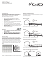
FIELD OF VIEW
The mini Opal has 10 Fresnel lenses that focus areas
onto the receptor. The 10 lens areas give 10 elds of view
as follows: 5 long-range (lenses 0 to 4) and 5 medium- to
short range (lenses 5 to 9). Movement between elds
produces a stronger response than movement towards
or away from the sensor in the same eld. The 10 lenses
monitor the area in front of the sensor as shown in the
gure..
Figure 1: Diagram showing the 10 lenses and their views.
Mini Opal
GJD332 30m External PIR
0 10 20 30 metres
0
5
10
15
5
10
15
0
1
2
3
4
56
7
8
9
0
3
20 30
5 deg
10
6
020 30
15 deg
10
1.5
020 30
-5 deg
10
6
0
45 deg
50
5 5

INSTALL
Caution: To avoid damage to your unit or incorrect tting,
take account of the following cautions:
1. The mini Opal is design for mounting vertically on
a at surface. Do not mount it on the underside of
a roof edge because the sensor cannot be angled
correctly in this orientation.
2. The range and focus of the mini Opal can be affected
by grease on the lens or sensor, Always hold the lens
by the edges and do not touch the sensor. If touched,
clean with an appropriate soft, lint-free cloth.
3. Do not install your mini Opal outside during wet
conditions such as rain or mist. Moisture inside the
case can cause faults. The moisture will remain in the
air-tight enclosure indenitely.
MOUNT
1. Choose a mounting position, it should:
- Be 60cm (2ft) from lamps
- If possible, allow the wiring to be run through
the wall
- Be smooth enough to hold the tamper plate
in position and provide a good seal against the
expanded foam back plate
- Make allowance for obstacles that may cause
a varying thermal image. For example, trees
or shrubs in a wind, ripples on ponds (or large
puddles), boiler ues and animals
2. Remove the cover
3. To reveal the two cable access, unscrew the top,
plastic wing-nut and, remove the circuit board and
lens unit.
4. The cable entry holes are protected by two sealed
grommets. Use a screwdriver to punch out the centre
of the grommets you intend using.
5. Hold the unit to the mounting surface and mark the
location of mounting and cabling holes.
WARNING: To prevent damage to the unit, do not drill
through the holes in the back of the case.
Always make the appropriate checks to ensure that the
surface you are drilling does not contain mains electrical
wiring or plumbing. Failure to do so can result in injury or
death by electric shock.
6. Feed the cable(s) through the grommet(s) and x the
unit in your chosen location using appropriate xings.
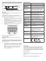
CONNECT: To prevent damage to your mini Opal or
lighting controller, switch off the power before making
connections
1. Connect the +, A, S and wires to the screw-terminal
block on the back of the sensor PCB.
Figure 6: Rear of PCB with Connections
2. Optionally connect the tamper output on the top PCB to your
alarm system.
NOTE: The twin tamper switches provide a single volts-free,
normally-closed alarm output once the mini Opal is mounted to the
wall and the cover is tted.
Figure 7: mini Opal tamper board
3. If required, see Connect External Buzzer or Relay (on Page
2/3)
When the power is applied, the red LED ashes for 0.6 seconds
before stopping. The LED is normally off during operation.
CONNECT EXTERNAL BUZZER OR RELAY
The unit can drive and external relay output or a piezo buzzer. The
component specications for the diagrams are:
• Diodes: 1N4148 / 1N4002 or similar - observe the band when
connecting
• External relay: 12V DC, 470ohm minimum coil resistance
• Piezo buzzer: 12 V DC, 3mA, 80dB (A) at one metre
Energizing a relay from the A or S connections
When the external relay is connected to the A connection, it will
trigger for every detection and deactivate immediately. By connecting
the relay to the S connection, the external relay stays active from 60s
following the last detection.
Figure 8: External relay wiring digram
N/C TAMPER
Case
Tamper
+
-
+
A
S
+
A
S
12V DC
mini
Opal GJD
Lighting
Controller

DRIVING A PIEZO BUZZER FROM THE A CONNECTION
This conguration can be useful as a temporary measure during your
walk-test. The piezo buzzer will sound every time a detection takes
place.
Figure 9: Piezo buzzer wring diagram
WALK TEST
The walk test iterates through the following adjustments until the
correct area is covered.
TIP: The eld of view of the mini Opal is affected by the cover.
Always perform the walk test with the cover tted removing the cover
each time you need to make adjustments.
1. Adjust the aim of the sensor, loosen the top and side plastic
wing-nuts and swivel the bracket. Tighten the wing-nuts again
and replace the cover.
2. Congure the eld of view by blanking lens area as necessary.
You may want to blank parts of the eld using the vertical
curtains or by cutting the foil sticker to size. Apply the sticker
to smooth, rear side of the lens.
3. Adjust the range between 8 and 30 metres using the PCB
mounted pot.
Figure 10: Range and lux potentiometers
DUSK ADJUSTMENT
Adjust the lux level for the day-night setting using the lux PCB
mounted pot.
The S output is factory set to start operating at dusk. That is, when
the light level falls below 5 lux. If the ambient night-time light levels
are higher than 5 lux then the S output will remain inactive and your
lights will not turn on.
• If the light level in your installation is about 5 lux at night (lights
do not operate), increase the light level at which the S output
starts to operate, by turning the lux pot clockwise towards
24HR.
• To set the S output to detect continuously, day or night,
independent of light level, turn the lux pot all the way to
maximum, marked 24HR.
+
-
+
A
S
+
A
S
12V DC
mini
Opal GJD
Lighting
Controller
SPECIFICATIONS
Coverage (max) 90° at 30m, equivalent to 625m²
Range Adjustable 8m to 30m
Directional
adjustment
±90° horizontal (180°), ±45° vertical
Area adjustment
(blanking)
Supplied with,1 foil label for near/
far beam blanking and 4 vertical
opaque curtains for zone blanking
Lens 2 rows of 10 beams
Sensor White light lter prevents false
triggering when sunny
Ouput A (Alarm) Open-collector transistor switch.
12V, 25mA alarm current.
Output S (Sen-
sor, daylight)
Open-collector transistor switch,
12V, 25mA alarm current
Output T (Tam-
per)
Volts-free, normally-open switch
output
Tamper switches Case open and removal from wall
Power 9 to 15V DC
Current 4mA at 12V
Operating
Temperature
-20°C to +55°C
Protection IP55, high-impact ABS housing,
Conformal coated electronics
(moisture and UV protection
lacquer)
Dimensions 84 x 106 x 72 mm
Mounting Suggested height 3m
Cabling 0 to 200mm: standard, 4-core,
7.0.2mm alarm cable
200 to 500m: 8-core, 16/0.2mm
(use double cores)
Certications
APPROVALS
The manufacturer declares that the product supplied is compliant
with the provisions of the EMC Directive 89/336/EEC amended
92/31/EEC for Electromagnetic Compatibility, and the Restriction of
Hazardous Substances Directive (RoHS) 2002/95/EC. A Declaration
of Conformity in accordance with the above directives is held on le
with the manufacturer.
Copyright Notice
GJD Reserve the right to amend specications without
notice.
Copyright © 2010 GJD Manufacturing Limited

Unit 2 Birch Business Park, Whittle Lane, Heywood, Greater Manchester, OL10 2SX, UK
www.gjd.co.uk [email protected] +44 (0) 1706 363 998
ENGINEER NOTES
-
 1
1
-
 2
2
-
 3
3
-
 4
4


GJD 20109693 Owner's manual
- Type
- Owner's manual
- This manual is also suitable for
Ask a question and I''ll find the answer in the document
Finding information in a document is now easier with AI
Related papers


Other documents
-
DirekTronik 20109790 Owner's manual
-
Satel OPAL Pro User manual
-
Satel OPAL Plus User guide
-
Satel OPAL Outdoor User manual
-
Genesis LG2 WP-6004 Installation Handbook
-
Robus RKN12050DA-01 Product information
-
-
Acclaim Lighting FLEX ECO INTERIOR User guide
-
-
Fracarro 918129 Datasheet