Page is loading ...

© 2005 Directed Electronics—Vista, CA
N572P 07-05
NOTE: This product is intended for installation by a professional installer only!
Any attempt to install this product by any person other than a trained professional
may result in severe damage to a vehicle’s electrical system and components.
PPyytthhoonn
MMooddeell 557711XXPP
IInnssttaallllaattiioonn GGuuiiddee

22
© 2005 Directed Electronics—all rights reserved
ttaabbllee ooff ccoonntteennttss
Bitwriter®, Code Hopping™, Doubleguard®, ESP™, FailSafe®, Ghost Switch™, Learn
Routine™, Nite-Lite®, Nuisance Prevention® Circuitry, Revenger®, Silent Mode™, Soft
Chirp®, Stinger®, Valet®, Vehicle Recovery System®, VRS®, and Warn Away® are all
Trademarks or Registered Trademarks of Directed Electronics.
wwaarrnniinngg!! ssaaffeettyy ffiirrsstt .. .. .. .. .. .. .. .. .. .. .. .. .. .. .. .. .. .. .. .. .. 33
iinnssttaallllaattiioonn ppooiinnttss ttoo rreemmeemmbbeerr .. ..
.. .. .. .. .. .. .. .. .. .. .. 44
before beginning the installation. . . . . . . . . . 4
after the installation . . . . . . . . . . . . . . . . . . 4
ddeecciiddiinngg oonn ccoommppoonneenntt llooccaattiioonnss .. .. .. .. .. .. .. .. .. .. .. .. 44
control module . . . . . . . . . . . . . . . . . . . . . . 4
mounting the antenna . . . . . . . . . . . . . . . . . 5
valet/program switch . . . . . . . . . . . . . . . . . . 5
status LED . . . . . . . . . . . . . . . . . . . . . . . . . 6
optional starter kill relay . . . . . . . . . . . . . . . 6
ffiinnddiinngg tthhee wwiir
reess yyoouu nneeeedd.. .. .. .. .. .. .. .. .. .. .. .. .. .. .. .. .. 66
obtaining constant 12V . . . . . . . . . . . . . . . . 7
finding the 12V switched ignition wire . . . . . . 7
finding the starter wire . . . . . . . . . . . . . . . . 7
finding a (+) brake light wire . . . . . . . . . . . . 8
finding the accessory/heater wire . . . . . . . . . 8
finding the tachometer wire . . . . . . . . . . . . . 8
finding the wait-to-start bulb wire for diesels . 9
wwiirriinngg ddiiaaggrraammss .. .. .. .. .. .. .. .. .. .. .. .. .. .. .. .. .. ..
.. .. .. .. .. .. 99
primary harness (H1) wiring diagram . . . . . . . 9
remote start ribbon harness wiring diagram . . 10
heavy gauge relay satellite wiring diagram . . 11
auxiliary harness (H2) wiring diagram. . . . . . 11
remote start harness (H3) wiring diagram . . . 11
pprriimmaarryy hhaarrnneessss ((HH11)) wwiirree ccoonnnneeccttiioonn gguuiiddee .. .. .. .. 1122
remote start auxiliary harness wiring diagram 12
door lock harness (H4) wiring diagram . . . . . 12
rreellaayy ssaatteelllliittee iinntteerrffaaccee wwiir
ree ccoonnnneeccttiioonn gguuiiddee .. .. 1166
aauuxxiilliiaarryy hhaarrnneessss ((HH22)) wwiirree ccoonnnneeccttiioonn gguuiiddee .. .. .. 1177
rreemmoottee ssttaarrtt hhaarrnneessss (
(HH33)) wwiirree ccoonnnneeccttiioonn gguuiiddee.. 1199
nneeuuttrraall ssaaffeettyy sswwiittcchh iinntteerrffaaccee .. .. .. .. .. .. .. .. .. .. .. .. .. 2200
testing the neutral safety switch . . . . . . . . . 21
11999955 aanndd
nneewweerr vveehhiiccllee aannttii--tthheefftt ssyysstteemmss .. .. .. .. ..
((iimmmmoobbiilliizzeerrss)) .. .. .. .. .. .. .. .. .. .. .. .. .. .. .. .. .. .. .. .. .
. .. .. .. 2233
passlock I and passlock II (PL-1 and PL-2) . . 23
passkey III (PK-3), transponder-based systems23
bbyyppaassssiinngg GGMM vveehhiiccllee aannttii--tthheefftt ssyysstteemmss ((VVAATTSS)) .. 2244
pplluugg--iinn LLEEDD aanndd vvaalleett//pprrooggrraamm sswwiittcchh .
. .. .. .. .. .. .. .. 2255
pprrooggrraammmmeerr iinntteerrffaaccee,, 33--ppiinn ppoorrtt.. .. .. .. .. .. .. .. .. .. .. .. 2255
pprrooggrraammmmiinngg jjuummppeerrss .. ..
.. .. .. .. .. .. .. .. .. .. .. .. .. .. .. .. .. 2266
light flash (+)/(-) . . . . . . . . . . . . . . . . . . . 26
tach threshold on/off . . . . . . . . . . . . . . . . . 26
ttrraannssmmiitttteerr//rreecceeiivveerr lleeaarrnn rroouuttiinnee .. .. .. .. .. .. .. .. .. .. .. 2277
ttr
raannssmmiitttteerr ccoonnffiigguurraattiioonnss .. .. .. .. .. .. .. .. .. .. .. .. .. .. .. .. 2299
button configuration . . . . . . . . . . . . . . . . . 29
ssyysstteemm ffeeaattuurreess lleeaarrnn rroouuttiinnee .. .. .. .. .. .
. .. .. .. .. .. .. .. .. 3300
ffeeaattuurree mmeennuuss.. .. .. .. .. .. .. .. .. .. .. .. .. .. .. .. .. .. .. .. .. .. .. .. .. 3322
menu #1. . . . . . . . . . . . . . . . . . . . . . . . . . 32
menu #1. . . . . . . . . . . . . . . . . . . . . . . . . . 33
menu #2. . . . . . . . . . . . . . . . . . . . . . . . . . 33
menu #2. . . . . . . . . . . . . . . . . . . . . . . . . . 35
ttaacchh lleeaarrnniin
ngg .. .. .. .. .. .. .. .. .. .. .. .. .. .. .. .. .. .. .. .. .. .. .. .. .. 3377
sshhuuttddoowwnn ddiiaaggnnoossttiiccss .. .. .. .. .. .. .. .. .. .. .. .. ..
.. .. .. .. .. .. 3388
rraappiidd rreessuummee llooggiicc.. .. .. .. .. .. .. .. .. .. .. .. .. .. .. .. .. .. .. .. .. .. 3399
rreeaarr ddeeffooggggeerr ccoonnttrro
oll .. .. .. .. .. .. .. .. .. .. .. .. .. .. .. .. .. .. .. .. 3399
ttiimmeerr mmooddee .. .. .. .. .. .. .. .. .. .. .. .. .. .. .. .. .. .. .. .. .. .. ..
.. .. .. 4400
vvaalleett mmooddee .. .. .. .. .. .. .. .. .. .. .. .. .. .. .. .. .. .. .. .. .. .. .. .. .. .. .. 4400
ssaaffeettyy cchheecckk .. .. .. .. .. ..
.. .. .. .. .. .. .. .. .. .. .. .. .. .. .. .. .. .. .. .. 4400
ttrroouubblleesshhoooottiinngg .. .. .. .. .. .. .. .. .. .. .. .. .. .. .. .. .. .. .. .. ..
.. .. 4422
wwiirriinngg qquuiicckk rreeffeerreennccee gguuiiddee .. .. .. .. .. .. .. .. .. .. .. .. .. .. .. 4444
rreellaayy ssaatteelllliittee wwiirriinngg qquuiicckk rreef
feerreennccee gguuiiddee .. .. .. .. .. 4455
The Bitwriter
®
(p/n 998T)
requires chip version 202 or
newer to program this unit.

© 2005 Directed Electronics—all rights reserved
33
wwaarrnniinngg!! ssaaffeettyy ffiirrsstt
The following safety warnings must be observed at all times:
■ Due to the complexity of this system, installation of this product must only be performed by an authorized
Directed dealer.
■ When properly installed, this system can start the vehicle via a command signal from the remote control
transmitter. Therefore, never operate the system in an area that does not have adequate ventilation. The fol-
lowing precautions are the sole responsibility of the user; however, authorized Directed dealers should make
the following recommendations to all users of this system:
1. Never operate the system in an enclosed or partially enclosed area without ventilation (such as a garage).
2. When parking in an enclosed or partially enclosed area or when having the vehicle serviced, the remote
start system must be disabled using the installed toggle switch.
3. It is the user's sole responsibility to properly handle and keep out of reach from children all remote
control transmitters to assure that the system does not unintentionally remote start the vehicle.
4.
TTHHEE UUSSEERR MMUUSSTT IINNSSTTAALLLL AA CCAARRBBOONN MMOONNOOXXIIDDEE DDEETTEECCTTOORR IINN OORR AABBOOUUTT TTHHEE LLIIVVIINNGG AARREEAA AADDJJAACCEENNTT TTOO
T
THHEE VVEEHHIICCLLEE.. AALLLL DDOOOORRSS LLEEAADDIINNGG FFRROOMM AADDJJAACCEENNTT LLIIVVIINNGG AARREEAASS TTOO TTHHEE EENNCCLLOOSSEEDD OORR PPAARRTTIIAALLLLYY
EENNCCLLOOSSEEDD VVEEHHIIC
CLLEE SSTTOORRAAGGEE AARREEAA MMUUSSTT AATT AALLLL TTIIMMEESS RREEMMAAIINN CCLLOOSSEEDD..
■ Use of this product in a manner contrary to its intended mode of operation may result in property damage,
personal injury, or death. Except when performing the Safety Check outlined in this installation guide, (1)
Never remotely start the vehicle with the vehicle in gear, and (2) Never remotely start the vehicle with the
keys in the ignition. The user will be responsible for having the neutral safety feature of the vehicle period-
ically checked, wherein the vehicle must not remotely start while the car is in gear. This testing should be
performed by an authorized Directed Electronics dealer in accordance with the Safety Check outlined in this
product installation guide. If the vehicle starts in gear, cease remote start operation immediately and consult
with the user to fix the problem immediately.
■ After the remote start module has been installed, test the remote start module in accordance with the Safety
Check outlined in this installation guide. If the vehicle starts when performing the Neutral Safety Shutdown
Circuit test, the remote start unit has not been properly installed. The remote start module must be removed
or properly reinstalled so that the vehicle does not start in gear. All installations must be performed by an
authorized Directed Electronics dealer.
OOPPEERRAATTIIOONN OOFF TTHHEE RREEMMOOTTEE SSTTAARRTT MMOODDUULLEE IIFF TTHHEE V
VEEHHIICCLLEE SSTTAARRTTSS IINN
GGEEAARR IISS CCOONNTTRRAARRYY TTOO IITTSS IINNTTEENNDDEEDD MMOODDEE OOFF OOPPEERRAATTIIOONN.. OOPPEERRAATTIINNGG TTHHEE RREEMMOOTTEE SSTTAARRTT SSYYSST
TEEMM UUNNDDEERR
TTHHEESSEE CCOONNDDIITTIIOONNSS MMAAYY RREESSUULLTT IINN PPRROOPPEERRTTYY DDAAMMAAGGEE OORR PPEERRSSOONNAALL IINNJJUURRYY.. IIMMMMEEDDIIAATTEELLYY CCEEAASSEE TTHHEE UUS
SEE
OOFF TTHHEE UUNNIITT AANNDD RREEPPAAIIRR OORR DDIISSCCOONNNNEECCTT TTHHEE IINNSSTTAALLLLEEDD RREEMMOOTTEE SSTTAARRTT MMOODDUULLEE.. DDIIRREECCTTEEDD EELLEECCTTRROONNIICCSS
WWIILLLL
NNOOTT BBEE HHEELLDD RREESSPPOONNSSIIBBLLEE OORR PPAAYY FFOORR IINNSSTTAALLLLAATTIIOONN OORR RREEIINNSSTTAALLLLAATTIIOONN CCOOSSTTSS..

44
© 2005 Directed Electronics—all rights reserved
iinnssttaallllaattiioonn ppooiinnttss ttoo rreemmeemmbbeerr
IIMMPPOORRTTAANNTT!!
This product is designed for fuel-injected, automatic transmission vehicles only.
Installing it in a standard transmission vehicle is dangerous and is contrary to its intended use.
■ Please read this entire installation guide before beginning the installation. The installation of this remote start
system requires interfacing with many of the vehicle’s systems. Many new vehicles use low-voltage or multi-
plexed systems that can be damaged by low resistance testing devices, such as test lights and logic probes
(computer safe test lights). Test all circuits with a high quality digital multi-meter before making connections.
■ Do not disconnect the battery if the vehicle has an anti-theft-coded radio. If equipped with an air bag, avoid
disconnecting the battery if possible. Many airbag systems will display a diagnostic code through their
warning lights after they lose power. Disconnecting the battery requires this code to be erased, which can
require a trip to the dealer.
■ Remove the domelight fuse. This prevents accidentally draining the battery.
■ Roll down a window to avoid being locked out of the car.
■ Test all functions. The "Using Your System" section of the Owner's Guide is very helpful when testing.
■ Complete the vehicle
Safety Check
outlined in this manual prior to the vehicle reassembly.
ddeecciiddiinngg oonn ccoommppoonneenntt llooccaattiioonnss
Things to remember when positioning the control module:
■ Never place the control module in the engine compartment!
■ The first thing a thief will do when hot-wiring a vehicle is to remove the driver's side under-dash panel to
access the starter and ignition wires. You should therefore avoid placing the control module just behind the
driver’s side dash to prevent it from being easily disconnected during a theft attempt.
■ When locating the control module, try to find a secure location that will not require you to extend the harness
wires (they are 1.5 meters long).
■ Keep the control module away from the heater core (or any other heat sources) and any obvious leaks.
ccoonnttrrooll mmoodduullee
aafftteerr tthhee iinnssttaallllaattiioonn
bbeeffoorree bbeeggiinnnniinngg tthhee iinnssttaallllaattiioonn

© 2005 Directed Electronics—all rights reserved
55
The antenna position should be discussed with the vehicle’s owner prior to installation, since the antenna may
be visible to the vehicle’s operator. The best location for the antenna is centered high on either the front or rear
windshield. For optimal range, the antenna should be mounted vertically. It can be mounted horizontally in rela-
tion to the windshield or under the dashboard away from metal, but range will be diminished. Metallic window
tint can also affect range, so this should be a consideration when determining the mounting location.
After determining the best mounting location, follow these steps:
1. Clean the mounting area with a quality glass cleaner or alcohol to remove any dirt or residue.
3. Mount the antenna using the supplied double-sided tape.
4. Route the antenna cable to the control module and plug it into the antenna connector.
IIMMPPOORRTTAANNTT!!
To achieve the best possible range, DO NOT leave the antenna cable bundled under
the dash. Always extend the cable full length during installation, regardless of the antenna
mounting location.
Ensure that the location you pick for this switch has sufficient clearance to the rear. The switch should be well
hidden. It should be placed so that passengers or stored items (such as items placed in a glove box or center
console) cannot accidentally bump it. The switch fits in a
9
/32-inch hole.
IIMMPPOORRTTAANNTT!!
When the vehicle is delivered, please show the user where the Valet/Program switch
is located and how to disarm the system using the switch.
vvaalleett//pprrooggrraamm sswwiittcchh
mmoouunnttiinngg tthhee aanntteennnnaa

66
© 2005 Directed Electronics—all rights reserved
Things to remember when positioning the status LED:
■ It should be visible from both sides and the rear of the vehicle, if possible.
■ It needs at least
1
/2-inch clearance to the rear.
■ It is easiest to use a small removable panel, such as a switch blank or a dash bezel. Remove it before drilling
your
9
/32-inch hole.
■ Use quick-disconnects near the LED wires if the panel is removable. This lets mechanics or other installers
remove the panel without having to cut the wires.
If the optional starter kill relay or its connections are immediately visible upon removal of the under-dash panel,
they can easily be bypassed. Always make the relay and its connections difficult to discern from the factory
wiring! Exposed yellow butt connectors do not look like factory parts, and will not fool anyone! For this reason,
routing the starter kill wires away from the steering column is recommended.
ffiinnddiinngg tthhee wwiirreess yyoouu nneeeedd
Now that you have determined where each component will be located, your next step is to find the wires in the
vehicle that the security system will be connected to.
IIMMPPOORRTTAANNTT!!
Do not use a 12V test light to locate these wires! All testing described in this
manual assumes the use of a digital multimeter.
ooppttiioonnaall ssttaarrtteerr kkiillll rreellaayy
ssttaattuuss LLEEDD

© 2005 Directed Electronics—all rights reserved
77
We recommend two possible sources for 12V constant: The (+) terminal of the battery, or the constant 12V supply to
the ignition switch. Always install a fuse within 12 inches of this connection. If the fuse will also be powering other
circuits, such as door locks, a power window module, or a Nite-Lite® headlight control system, fuse accordingly.
IIMMPPOORRTTAANNTT!!
Do not remove the fuse holder on the red wire. It ensures that the control module
has its own fuse, of the proper value, regardless of how many accessories are added to the main
power feed.
The ignition wire is powered when the key is in the run or start position. This is because the ignition wire powers
the ignition system (spark plugs, coil) as well as the fuel delivery system (fuel pump, fuel injection computer).
Accessory wires lose power when the key is in the start position to make more current available to the starter motor.
HHooww ttoo ffiinndd ((++))1122VV iiggnniittiioonn wwiitthh yyoouurr mmuullttiimmeetteerr::
1. Set to DCV or DC voltage (12V or 20V is fine).
2. Attach the (-) probe of the meter to chassis ground.
3. Probe the wire you suspect of being the ignition wire. The steering
column harness or ignition switch harness is an excellent place to find
this wire.
4. Turn the ignition key switch to the run position. If your meter reads
(+)12V, go to the next step. If it does not read (+)12V, probe another wire.
5. Now turn the key to the start position. The meter display should stay steady, not dropping by more than a
few tenths of a volt. If it drops close to or all the way to zero, go back to Step 3. If it stays steady at (+)12V,
you have found an ignition wire.
The starter wire provides 12V directly to the starter or to a relay controlling the starter. In some vehicles, it is
necessary to power a cold start circuit. A cold start circuit will test exactly like a starter circuit, but it does not
control the starter. Instead, the cold start circuit is used to prime the fuel injection system for starting when the
vehicle is cold.
ffiinnddiinngg tthhee ssttaarrtteerr wwiirree
ffiinnddiinngg tthhee 1122VV sswwiittcchheedd iiggnniittiioonn wwiirree
oobbttaaiinniinngg ccoonnssttaanntt 1122VV

88
© 2005 Directed Electronics—all rights reserved
HHooww ttoo ffiinndd tthhee ssttaarrtteerr wwiirree wwiitthh yyoouurr mmuullttiimmeetteerr::
1. Set to DCV or DC voltage (12V or 20V is fine).
2. Attach the (-) probe of the meter to chassis ground.
3. Probe the wire you suspect of being the starter wire. The steering
column is an excellent place to find this wire. Remember you do not
need to interrupt the starter at the same point you test it. Hiding your
optional starter kill relay and connections is always recommended.
4. Turn the ignition key switch to the start position. Make sure the car is
not in gear! If your meter reads (+)12V, go to the next step. If it doesn’t, probe another wire.
5. Cut the wire you suspect of being the starter wire.
6. Attempt to start the car. If the starter engages, reconnect it and go back to Step 3. If the starter does not
turn over, you have the right wire.
Most vehicles use a (+) brake light circuit. The (+) brake light wire is often found near the brake pedal. The same
wire can often be accessed in the kick panel or running board.
HHooww ttoo ffiinndd aa ((++)) bbrraakkee lliigghhtt wwiirree wwiitthh y
yoouurr mmuullttiimmeetteerr::
1. Set to DCV or DC voltage (12V or 20V is fine).
2. Attach the (-) probe of the meter to chassis ground.
3. Probe the wire you suspect of being the brake light wire.
4. Press the brake pedal. If your meter shows (+)12V, release the brake pedal and make sure it goes back to zero.
5. If it does return to zero, this is the correct brake wire.
An accessory/heater wire will show +12V when the key is in the accessory and run positions. It will not show
+12V during the cranking cycle. There will often be more than one accessory wire in the ignition harness. The
correct accessory wire will power the vehicle's climate control system. Some vehicles may have separate wires for
the blower motor and the air conditioning compressor. In such cases, it will be necessary to add a relay to power
the second accessory wire.
To test for a tachometer wire, a multimeter capable of testing AC voltage must be used. The tachometer wire will
show between 1V and 6V AC. In multi-coil ignition systems, the system can learn individual coil wires. Individual
coil wires in a multi-coil ignition system will register lower amounts of AC voltage. Also, if necessary, the system
can use a fuel injector control wire for engine speed sensing. Common locations for a tachometer wire are the
ignition coil itself, the back of the gauges, engine computers, and automatic transmission computers.
ffiinnddiinngg tthhee ttaacchhoommeetteerr wwiirree
ffiinnddiinngg tthhee aacccceessssoorryy//hheeaatteerr wwiirree
ffiinnddiinngg aa ((++)) bbrraakkee lliigghhtt wwiirree

© 2005 Directed Electronics—all rights reserved
99
IIMMPPOORRTTAANNTT!!
Do not test tachometer wires with a test light or logic probe. The vehicle will be
damaged.
HHooww ttoo ffiinndd aa ttaacchhoommeetteerr wwiirree wwiitthh yyoouurr mmuullttiimmeetteerr::
1. Set to ACV or AC voltage (12V or 20V is fine).
2. Attach the (-) probe of the meter to chassis ground.
3. Start and run the vehicle.
4. Probe the wire you suspect of being the tachometer wire with the red probe of the meter.
5. If this is the correct wire the meter will fluctuate with the rpm of the motor and read between 1V and 6V.
In diesel vehicles it is necessary to interface with the wire that turns on the WAIT TO START light in the dash-
board. This wire illuminates the bulb until the vehicle’s glow plugs are properly heated. When the light goes out
the vehicle can be started. This wire is always available at the connector leading to the bulb in the dashboard.
It can also be found at the Engine Control Module (ECM) in many vehicles.
TToo tteesstt aanndd ddeetteerrmmiinnee tthhee ppoollaarriittyy ooff tthhiiss w
wiirree::
1. Set your multimeter to DCV or DC voltage (12 or 20V is fine).
2. Attach the (+) probe of the meter to (+)12V.
3. Probe the wire that you suspect leads to the bulb with the (-) probe of the meter.
4. Turn the ignition switch to the ON position.
5. If the meter indicates 12 volts until the light goes out you have isolated the correct wire and the wire's polar-
ity is negative (ground while the bulb is on).
6. If the meter reads zero volts until the light goes out and then reads 12 volts, you have isolated the correct
wire and the wire's polarity is positive.
wwiirriinngg ddiiaaggrraammss
The primary harness supplied with this unit is the standard 12-pin harness used by Directed Electronics security
systems. Three wires in the plug are not used. The upgrade from this unit to a security system would simply
require unplugging and exchanging control units and connecting the necessary wires to the vehicle. The func-
tions of all the wires that are used in the primary harness are outlined in the following wiring diagram and the
wire connections are described in the wire connection guides.
pprriimmaarryy hhaarrnneessss ((HH11)) wwiirriinngg ddiiaaggrraamm
ffiinnddiinngg tthhee wwaaiitt--ttoo--ssttaarrtt bbuullbb wwiirree ffoorr ddiieesseellss

1100
© 2005 Directed Electronics—all rights reserved
______
______
______
______
______
______
______
______
______
______
______
______
______
______
______
______
______
______
______
BBLLUUEE ((--)) 220000 mmAA SSTTAATTUUSS OOUUTTPPUUTT
OORRAANNGGEE//BBLLAACCKK ((--)) AANNTTII--GGRRIINNDD OOUUTTPPUUTT//GGRROOUUNNDD WWHHEENN AARRMMEEDD OOUUTTPPUUTT
PPUURRPPLLEE ((--)) 220000 mmAA SSTTAARRTTEERR RREELLAAYY TTUURRNN--OONN
OORRAANNGGEE ((--)) 220000 mmAA AACCCCEESSSSOORRYY RREELLAAYY TTUURRNN--OONN
PPIINNKK ((--)) 220000 mmAA IIGGNNIITTIIOONN RREELLAAYY TTUURRNN--OONN
YYEELLLLOOWW ((++)) IIGGNNIITTIIOONN IINNPPUUTT TTOO RREEMMOOTTEE SSTTAARRTT
PPIINNKK//WWHHIITTEE ((--)) 220000 mmAA PPRROOGGRRAAMMMMAABBLLEE AACCCC//IIGGNN OOUUTTPPUUTT
11
22
33
44
55
66
77
rreemmoottee ssttaarrtt rriibbbboonn hhaarrnneessss wwiirriinngg ddiiaaggrraamm
RREEDD//WWHHIITTEE ((--))220000 mmAA CCHHAANNNNEELL 22 VVAALLIIDDIITTYY OOUUTTPPUUTT
RREEDD ((++)) CCOONNSSTTAANNTT PPOOWWEERR IINNPPUUTT
BBRROOWWNN ((--)) HHOORRNN HHOONNKK OOUUTTPPUUTT
NNOO FFUUNNCCTTIIOONN
BBLLAACCKK ((--)) CCHHAASSSSIISS GGRROOUUNNDD IINNPPUUTT
NNOO FFUUNNCCTTIIOONN
BBLLUUEE ((--)) SSEECCOONNDD UUNNLLOOCCKK OOUUTTPPUUTT
NNOO FFUUNNCCTTIIOONN
BBLLAACCKK//WWHHIITTEE ((--))220000 mmAA DDOOMMEELLIIGGHHTT SSUUPPEERRVVIISSIIOONN OOUUTTPPUUTT
WWHHIITTEE//BBLLUUEE ((--)) RREEMMOOTTEE SSTTAARRTT AACCTTIIVVAATTIIOONN IINNPPUUTT
WWHHIITTEE ((++))//((--)) SSEELLEECCTTAABBLLEE LLIIGGHHTT FFLLAASSHH OOUUTTPPUUTT
OORRAANNGGEE ((--)) 550000 mmAA AARRMMEEDD OOUUTTPPUUTT
HH11//11
HH11//22
HH11//33
HH11//44
HH11//55
HH11//66
HH11//77
HH11//88
HH11//99
HH11//1100
HH11//1111
HH11//1122

© 2005 Directed Electronics—all rights reserved
1111
______
______
______
______
______
______
______
______
______
______
______
______
______
______
______
______
______
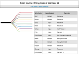
BBLLAACCKK//WWHHIITTEE ((--)) NNEEUUTTRRAALL SSAAFFEETTYY SSWWIITTCCHH IINNPPUUTT
VVIIOOLLEETT//WWHHIITTEE TTAACCHHOOMMEETTEERR IINNPPUUTT WWIIRREE
BBRROOWWNN ((++)) BBRRAAKKEE SSWWIITTCCHH SSHHUUTTDDOOWWNN WWIIRREE
GGRRAAYY ((--)) HHOOOODD PPIINNSSWWIITTCCHH SSHHUUTTDDOOWWNN WWIIRREE
BBLLUUEE//WWHHIITTEE ((--)) 220000 mmAA 22NNDD SSTTAATTUUSS//RREEAARR DDEEFFOOGGGGEERR -- LLAATTCCHHEEDD//PPUULLSSEEDD
HH33//11
HH33//22
HH33//33
HH33//44
HH33//55
rreemmoottee ssttaarrtt hhaarrnneessss ((HH33)) wwiirriinngg ddiiaaggrraamm
VVIIOOLLEETT//BBLLAACCKK ((--)) CCHHAANNNNEELL 44 OOUUTTPPUUTT
GGRREEEENN//WWHHIITTEE ((--)) FFAACCTTOORRYY RREEAARRMM OOUUTTPPUUTT
GGRRAAYY//BBLLAACCKK ((--)) WWAAIITT--TTOO--SSTTAARRTT IINNPPUUTT
GGRREEEENN//BBLLAACCKK ((--)) FFAACCTTOORRYY DDIISSAARRMM
HH22//11
HH22//22
HH22//33
HH22//44
aauuxxiilliiaarryy hhaarrnneessss ((HH22)) wwiirriinngg ddiiaaggrraamm
PPIINNKK//WWHHIITTEE ((++)) OOUUTTPPUUTT TTOO SSEECCOONNDD IIGGNNIITTIIOONN//AACCCCEESSSSOORRYY CCIIRRCCUUIITT
RREEDD//WWHHIITTEE HHIIGGHH CCUURRRREENNTT 1122VV IINNPPUUTT
PPIINNKK ((++)) OOUUTTPPUUTT TTOO IIGGNNIITTIIOONN CCIIRRCCUUIITT
RREEDD ((++)) ((3300AA)) HHIIGGHH CCUURRRREENNTT 1122VV IINNPPUUTT
OORRAANNGGEE ((++)) OOUUTTPPUUTT TTOO AACCCCEESSSSOORRYY CCIIRRCCUUIITT
RREEDD ((++)) ((3300AA)) HHIIGGHH CCUURRRREENNTT 1122VV IINNPPUUTT
GGRREEEENN SSTTAARRTTEERR IINNPPUUTT FFRROOMM IIGGNNIITTIIOONN ((KKEEYY SSIIDDEE))
PPUURRPPLLEE ((++)) SSTTAARRTTEERR OOUUTTPPUUTT TTOO SSTTAARRTTEERR ((SSTTAARRTTEERR SSIIDDEE))
11
22
33
44
55
66
77
88
hheeaavvyy ggaauuggee rreellaayy ssaatteelllliittee wwiirriinngg ddiiaaggrraamm

1122
© 2005 Directed Electronics—all rights reserved
______
______
______
______
______
______
______
pprriimmaarryy hhaarrnneessss ((HH11)) wwiirree ccoonnnneeccttiioonn gguuiiddee
This wire supplies a (-)500 mA ground as long as the system is armed. This output ceases as soon as the system
is disarmed. The orange wire may be wired to an optional Directed Electronics 8618 starter kill relay.
As shipped, this wire should be connected to the (+) parking light wire. If the light flash polarity jumper is moved
to the opposite position (see
Internal Programming Jumpers
section), this wire supplies a (-)200 mA output.
This is available for driving (-) light control wires in Toyota, Lexus, BMW, some Mitsubishi, some Mazda, and
various other models.
HH11//22 WWHHIITTEE ((++//--)) sseelleeccttaabbllee lliigghhtt ffllaasshh oouuttppuutt
HH11//11 OORRAANNGGEE ((--)) ggrroouunndd--wwhheenn--aarrmmeedd oouuttppuutt
PPUURRPPLLEE ((--)) 220000 mmAA SSTTAARRTTEERR RREELLAAYY TTRRIIGGGGEERR
PPIINNKK ((--)) 220000 mmAA IIGGNNIITTIIOONN RREELLAAYY TTRRIIGGGGEERR
OORRAANNGGEE ((--)) 220000 mmAA AACCCCEESSSSOORRYY RREELLAAYY TTRRIIGGGGEERR
BBLLUUEE ((--)) 220000 mmAA SSTTAATTUUSS OOUUTTPPUUTT
11
22
33
44
rreemmoottee ssttaarrtt aauuxxiilliiaarryy hhaarrnneessss wwiirriinngg ddiiaaggrraamm
BBLLUUEE ((++)) LLOOCCKK ((--)) UUNNLLOOCCKK
NNOO FFUUNNCCTTIIOONN
GGRREEEENN ((--)) LLOOCCKK ((++)) UUNNLLOOCCKK
HH44//11
HH44//22
HH44//33
ddoooorr lloocckk hhaarrnneessss ((HH44)) wwiirriinngg ddiiaaggrraamm

© 2005 Directed Electronics—all rights reserved
1133
((++)) PPoossiittiivvee LLiigghhtt FFllaasshh OOuuttppuutt
((--)) LLiigghhtt FFllaasshh OOuuttppuutt
NNOOTTEE::
For parking light circuits that draw 10 amps or more, the internal jumper must be switched
to a (-) light flash output. (See the Internal Programming Jumper section of this guide.)
PP//NN 88661177
or a standard automotive SPDT relay must be used on the H1/2 light flash output harness wire.
This input comes from the factory set to 2 activation pulses. This means that it is necessary to have 2 consecu-
tive ground pulses on the white/blue wire for the remote start to activate or to deactivate. The same holds true
for the remote control activation when set to a two pulse setting it is necessary to press the button twice
for the remote start to activate or deactivate.
NNOOTTEE::
When the activation pulse count can be programmed to 1, 2, or 3 pulses when changed
it will affect both activation inputs; the White/Blue wire and the remote control activation.
HH11//33 WWHHIITTEE//BBLLUUEE ((--)) rreemmoottee ssttaarrtt aaccttiivvaattiioonn iinnppuutt

1144
© 2005 Directed Electronics—all rights reserved
Connect this wire to the optional domelight supervision relay as shown below:
IIMMPPOORRTTAANNTT!!
This output is only intended to drive a relay. It cannot be connected directly to the
domelight circuit because the output cannot support the current draw of one or more light bulbs.
This output is used for progressive door unlock. A progressive unlock system unlocks the driver's door when the
unlock (disarm) button is pressed and unlocks the passenger doors if the unlock (disarm) button is pressed again
within 15 seconds after unlocking the driver's door. The BLUE wire outputs a low current (-) pulse on the second
press of the unlock button of the transmitter. This negative unlock output is used to unlock the passenger doors.
NNOOTTEE::
The second unlock output feature is not available if the double pulse unlock feature
is turned on.
Connect this wire to a clean, paint-free sheet metal location (driver kick panel) using a factory bolt that DOES
NOT have any vehicle component grounds attached to it. A screw should only be used when in conjunction with
a two-sided lock washer. Under dash brackets and door sheet metal are not acceptable ground points. It is rec-
ommended that all remote start components be grounded at the same location.
HH11//88 BBLLAACCKK ((--)) cchhaassssiiss ggrroouunndd ccoonnnneeccttiioonn
HH11//66 BBLLUUEE sseeccoonndd uunnlloocckk
HH11//44 BBLLAACCKK //WWHHIITTEE ((--)) 220000 mmAA ddoommeelliigghhtt ssuuppeerrvviissiioonn oouuttppuutt

© 2005 Directed Electronics—all rights reserved
1155
This wire supplies a (-) 200 mA output that can be used to honk the vehicle horn. It outputs a single pulse when
locking the doors with the remote, and two pulses when unlocking with the remote. This wire will also output
pulses for 30 seconds when the Panic Mode is activated. If the vehicle has a (+) horn circuit, an optional relay
can be used to interface with the system, as shown below.
Before connecting this wire, remove the supplied fuse. Connect to the battery positive terminal or the constant
12V supply to the ignition switch.
NNOOTTEE::
Always use a fuse within 12 inches of the point you obtain (+)12V. Do not use the 10A
fuse in the harness for this purpose. This fuse is intended to protect the module.
When the system receives the code controlling Channel 2, for longer than 1.5 seconds, the RED/WHITE wire will
supply an output as long as the transmission continues. This is often used to operate a trunk/hatch release or
other relay-driven function.
IIMMPPOORRTTAANNTT!!
Never use this wire to drive anything except a relay or low-current input! The transistorized output
can only supply 200 mA of current. Connecting directly to a solenoid, motor, or other high-current device will
cause it to fail. This wire is programmable, refer to Programming section.
HH11//1122 RREEDD//WWHHIITTEE CChhaannnneell 22,, ((--)) 220000 mmAA oouuttppuutt
HH11//1111 RREEDD ((++))1122VV ccoonnssttaanntt ppoowweerr iinnppuutt
HH11//1100 BBRROOWWNN ((--)) hhoorrnn hhoonnkk oouuttppuutt

1166
© 2005 Directed Electronics—all rights reserved
rreellaayy ssaatteelllliittee iinntteerrffaaccee wwiirree
ccoonnnneeccttiioonn gguuiiddee
All except the red heavy gauge wires leading from the relay satellite are used to energize high current circuits
in the vehicle. It is crucial that these connections are made correctly so that they are capable of handling the
current demands. For this reason, scotch locks, T-taps and other such connectors should not be used.
After cutting the starter wire connect the PURPLE wire to the end going to the starter motor.
After cutting the starter wire connect the GREEN wire to the end going to the key side of the ignition.
Remove the two 30 amp fuses prior to connecting these wires and do not replace them until the satellite has
been plugged into the control module. These wires are the source of current for all the circuits the relay satel-
lite will energize. They must be connected to a high current source. Since the factory supplies (+) 12V to the key
switch that is used to operate the motor, it is recommended that these wires be connected there.
NNOOTTEE::
If the factory supplies two separate (+) 12V feeds to the ignition switch, connect one RED
wire of the satellite to each feed at the switch.
Connect this wire to the accessory wire in the vehicle that powers the climate control system.
Connect this wire to the ignition wire in the vehicle.
PPIINNKK ((++)) iiggnniittiioonn oouuttppuutt
OORRAANNGGEE ((++)) aacccceessssoorryy oouuttppuutt
RREEDD ((22)) ((++))1122VV iinnppuutt ffoorr rreellaayyss
GGRREEEENN ssttaarrtteerr kkiillll
PPUURRPPLLEE ((++)) ssttaarrtteerr oouuttppuutt

© 2005 Directed Electronics—all rights reserved
1177
Connect this wire to the second ignition or accessory wire in the vehicle (selectable menu feature 2-9).
If additional current capacity is needed cut this wire, add a fuse adequate for the circuit to be supplied, and
connect to an additional 12V source.
aauuxxiilliiaarryy hhaarrnneessss ((HH22)) wwiirree ccoonnnneeccttiioonn gguuiiddee
This wire sends a negative pulse every time the remote start is activated or the doors are unlocked. This can be
used to pulse the disarm wire of the vehicle's factory anti-theft device. Use a relay to send a (-) or (+) pulse to
the disarm wire as shown in the following diagrams.
RReellaayy ffoorr NNeeggaattiivvee ((--)) DDiissaarrmm WWiirree RReellaayy ffoorr PPoossiittiivvee ((++)) DDiissaarrmm WWiirree
Connect this wire to the wire in the vehicle that sends the signal to turn on the WAIT-TO-START bulb in the dash-
board. In most diesels the wire is negative (ground turns on the bulb) and the GRAY/BLACK can be directly
connected to the wire in the vehicle. If the vehicle uses a positive wire (12V to turn on the bulb) a relay must
be used to change the polarity. (See
Finding the Wait-To-Start Bulb Wire For Diesels
section of this guide.) Here
are some common colors of this wire:
■ Chevrolet and GMC trucks: Light Blue or Dark Blue
■ Ford Trucks: Black/Pink
■ Dodge Ram Trucks: Orange/Black or Black/Orange
HH22//22 GGRRAAYY//BBLLAACCKK ((--)) ddiieesseell wwaaiitt--ttoo--ssttaarrtt bbuullbb iinnppuutt
HH22//11 GGRREEEENN//BBLLAACCKK ((--)) ffaaccttoorryy aallaarrmm ddiissaarrmm
RREEDD//WWHHIITTEE 1122 VV iinnppuutt
PPIINNKK//WWHHIITTEE ((++)) oouuttppuutt ttoo sseeccoonndd iiggnniittiioonn//aacccceessssoorryy cciirrccuuiitt

1188
© 2005 Directed Electronics—all rights reserved
NNOOTTEE!!
A 1-amp diode must be installed in line on the factory wire between the wait-to-start
indicator and the ECM. (See the following diagram for details.)
This wire sends a negative pulse every time the remote start shuts down or the doors are locked. This can be used
to pulse the arm wire of the vehicle's factory anti-theft device. Use a relay to send a (-) or (+) pulse to the arm wire.
This wire provides 200 mA programmable output. (See
Feature Descriptions
section of this guide.)
HH22//44 VVIIOOLLEETT//BBLLAACCKK ((--)) cchhaannnneell 44 oouuttppuutt
HH22//33 GGRREEEENN//WWHHIITTEE ffaaccttoorryy rreeaarrmm oouuttppuutt

© 2005 Directed Electronics—all rights reserved
1199
rreemmoottee ssttaarrtt hhaarrnneessss ((HH33)) wwiirree ccoonnnneeccttiioonn gguuiiddee
This wire supplies a 200mA output as soon as the module begins the remote start process. The H3/1 BLUE wire
can also be used to activate the defogger trigger (latched/pulsed) 10-seconds after the remote start engages.
(See the
Feature Descriptions
section in this guide for details about programming this output.)
This wire MUST be connected to hood pinswitch. This input will disable or shut down the remote start when the hood
is opened.
This wire MUST be connected to the vehicle's brake light wire. This is the wire that shows (+) 12V when the brake
pedal is pressed. The remote start will be disabled or shut down any time the brake pedal is pressed.
This input provides the module with information about the engine's revolutions per minute (RPMs). It can be
connected to the negative side of the coil in vehicles with conventional coils. In multi-coil and high energy igni-
tion systems locating a proper signal may be more difficult. (See
Installation Points to Remember
section of this
guide for finding the tachometer wire.) Once connected, you must teach the system the tach signal. (See
Tach
Learning
section of this guide.)
Connect this wire to the toggle (override) switch as shown in Figure A. Connect the other wire from the toggle
switch to the PARK/NEUTRAL switch in the vehicle. This wire will test with ground with the gear selector either
in PARK or NEUTRAL. This will prevent the vehicle from accidentally being started while in a drive gear. This input
MUST rest at ground in order for the remote start system to operate. Connected properly the vehicle will only
start while in PARK or NEUTRAL.
In some vehicles, the PARK/NEUTRAL position switch activates a factory starter lock out that will not allow the
starter to operate in a drive gear. In these vehicles, connect this wire to the toggle switch as shown in Figure
B. Connect the other wire from the toggle switch to chassis ground.
HH33//66 BBLLAACCKK//WWHHIITTEE nneeuuttrraall ssaaffeettyy sswwiittcchh iinnppuutt
HH33//55 VVIIOOLLEETT//WWHHIITTEE ttaacchhoommeetteerr iinnppuutt
HH33//44 BBRROOWWNN ((++)) bbrraakkee sswwiittcchh iinnppuutt
HH33//33 GGRRAAYY ((--)) hhoooodd ppiinnsswwiittcchh iinnppuutt
HH33//11 BBLLUUEE//WWHHIITTEE ssttaattuuss//ddeeffooggggeerr oouuttppuutt

2200
© 2005 Directed Electronics—all rights reserved
FFiigguurree AA FFiigguurree BB
IIMMPPOORRTTAANNTT!!
Always perform the Vehicle Safety Check section of this guide to verify that the
vehicle cannot be started in ANY drive gear and that the override switch is functioning properly.
nneeuuttrraall ssaaffeettyy sswwiittcchh iinntteerrffaaccee
Some vehicles combine the column shift mechanism and the mechanical neutral safety switch into one mechan-
ical part. In these vehicles, it is impossible to interface the remote start system before the neutral safety switch.
With this type of vehicle, if the vehicle is left in a drive gear and the remote start system is activated, the vehicle
will move and may cause damage to persons or property.
According to available information, vehicles known to be manufactured this way are most General Motors trucks,
sport utility vehicles and column shifting passenger vehicles. Available information also indicates that pre-1996
Dodge Dakota pickups with 2.5 liter motors are also manufactured this way.
GM vehicles that have the neutral safety switch built into the column shifter can usually be identified by a purple
starter wire. Typically, vehicles that use an outboard mechanical switch use a yellow wire from the ignition switch
to the mechanical switch and a purple wire from the mechanical switch to the starter itself. Remember, this is
only a rule of thumb and is not intended as a substitute for proper testing.
We suggest the following procedure to test for vehicles manufactured in this way.
NNOOTTEE::
You must complete the remote start system installation before doing the following test.
Ensure that the remote start system is functioning normally. This includes connecting to the
brake as a shut-down.
/