Diamond Systems DS-MPE-SER4M is a PCIe MiniCard that provides four high-speed serial ports with configurable protocols. It supports RS-232, RS-422, and RS-485 data transmission standards. With data rates reaching 1Mbps for RS-232 and 10Mbps for RS-422/RS-485, this card is suitable for various industrial and embedded applications requiring reliable serial data communication.
Diamond Systems DS-MPE-SER4M is a PCIe MiniCard that provides four high-speed serial ports with configurable protocols. It supports RS-232, RS-422, and RS-485 data transmission standards. With data rates reaching 1Mbps for RS-232 and 10Mbps for RS-422/RS-485, this card is suitable for various industrial and embedded applications requiring reliable serial data communication.


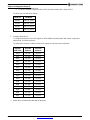
-
 1
1
-
 2
2
-
 3
3
-
 4
4
-
 5
5
-
 6
6
-
 7
7
-
 8
8
-
 9
9
-
 10
10


Diamond Systems DS-MPE-SER4M User manual
- Type
- User manual
- This manual is also suitable for
Diamond Systems DS-MPE-SER4M is a PCIe MiniCard that provides four high-speed serial ports with configurable protocols. It supports RS-232, RS-422, and RS-485 data transmission standards. With data rates reaching 1Mbps for RS-232 and 10Mbps for RS-422/RS-485, this card is suitable for various industrial and embedded applications requiring reliable serial data communication.
Ask a question and I''ll find the answer in the document
Finding information in a document is now easier with AI
Related papers
-
Diamond Systems DS-MPE-GE210 User manual
-
-
-
-
-
-
Diamond Systems DS-MPE-SER4M User manual
-
Diamond Systems FLOYD Carrier for Nano & Xavier NX User manual
-
-
Other documents
-
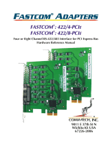 CommTech Fastcom 422/8-PCIe Reference guide
-
Diamond Aries PC/104-Plus SBC User manual
-
WinSystems SBC35-C398 User manual
-
-
Aplex APC-3420 User manual
-
Diamond Magellan MAG-965-1G User manual
-
Aaeon GENE-BT06 User manual
-
-
Eurotech Catalyst TC Owner's manual
-
Moxa CP-102U/102UL Series User manual
