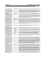
Everlast POWERTIG 210 EXT User manual
- Category
- Welding System
- Type
- User manual

PHASE
EVERLAST
POWERTIG
210 EXT
Operator’s Manual for the PowerTig 210EXT
Safety, Setup and General Use Guide
Rev. 2 0 00820-14
DIGITAL AC/DC PULSE TIG/STICK WELDER
CC
GTAW-P
SMAW
IGBT
1
~
AC/DC
everlastwelders.com
1-877-755-9353
329 Lileeld Ave. South San Francisco, CA 94080 USA
Specicaons and Accessories subject to change without noce.
120V
240V

2
Table of contents
Secon……………………………………………………………..Page
Leer to the Customer ………………...………………….
Everlast Contact Informaon…………………………….
Safety Precauons…………………………………………....
Introducon and Specicaons…………………….…..
Unit Specicaons……………………….……………………
General Overview…………….…..…………………………..
General Use and Care………...……………………………..
Quick Setup Guide, TIG Torch/Cooler Connecon
Quick Setup Guide, Sck Polarity……………………….
Rear Panel Gas Connecon and Wiring.…………….
Front Panel Features and Controls……………………..
Rear Panel Features and Controls……………………...
Welder Funcon Summary and Explanaons…….
Tungsten Preparaon………………………………………...
Li Start and High Frequency Start……………………
Sck Starng Methods………………………………………
Recommendaons for Polarity/Amps/Tungsten..
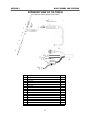
Expanded View of TIG torch……….…….……….………
7 Pin Connector Pinout………………….…….……………
Troubleshoong………………………………………………..
Trouble Codes…………………………………………………….
3
4
5
9
10
11
11
12
13
14
15
21
23
29
30
31
32
33
34
35
36
NOTE:
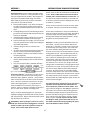
Product Specicaons and features are subject to change without noce. While every aempt has been made
to provide the most accurate and current informaon possible at the me of publicaon, this manual is intend-
ed to be a general guide and not intended to be exhausve in its content regarding safety, welding, or the oper-
aon/maintenance of this unit. Everlast Power Equipment INC. does not guarantee the accuracy, complete-
ness, authority or authencity of the informaon contained within this manual. The owner of this product as-
sumes all liability for its use and maintenance. Everlast Power Equipment INC. does not warrant this product or
this document for tness for any parcular purpose, for performance/accuracy or for suitability of applicaon.
Furthermore, Everlast Power Equipment INC does not accept liability for injury or damages, consequenal or
incidental, resulng from the use of this product or resulng from the content found in this document or accept
claims by a third party of such liability.

3
Dear Customer,
THANKS! You had a choice, and you bought an Everlast. We appreciate you
as a customer and hope that you will enjoy years of use from your welder.
Please go directly to the Everlast website to register your unit and to download your current war-
ranty informaon. Your unit registraon is important should any informaon such as product up-
dates or recalls be issued. It is also important so that we may track your sasfacon with Everlast
products and services. If you are unable to register by website, contact Everlast directly through
the sales department through the main customer service number in your country. Your unit will be
registered and warranty will be issued and in full eect. Keep all informaon regarding your pur-
chase. In the event of a problem you must contact technical support before your welder can be a
candidate for warranty service and returned.
Please review the current online warranty statement and informaon found on the web-
site of the Everlast division located in or nearest to your country. Print it for your records
and become familiar of its terms and condions.
Everlast oers full technical support, in several dierent forms. We have online support available
through email, and a welding support forum designed for customers and noncustomer interacon.
Technical advisors are acve on the forum daily. We also divide our support into two divisions:
technical and welding performance. Should you have an issue or queson concerning your unit,
please contact performance/technical support available through the main company headquarters
available in your country. For best service call the appropriate support line and follow up with an
email, parcularly if o hours, or you cannot reach a live person. In the event you do not reach a
live person, parcularly during heavy call volume mes, holidays, and o hours, leave a message
and your call will normally be returned within 24 hours. Also for quick answers to your basic ques-
ons, join the company owned forum available through the website. You’ll nd knowledgeable,
helpful people and sta available to answer your quesons, and perhaps nd a topic that already
addresses your queson at hp://www.everlastgenerators.com/forums/.
Should you need to call or write, always know your model name, purchase date and welder manu-
facturing inspecon date. This will assure the quick and accurate customer service. REMEMBER:
Be as specic and informed as possible. Technical and performance advisors rely upon you to
carefully describe the condions and circumstances of your problem or queson. Take notes of
any issues as best you can. You may be asked many quesons by the advisors to clarify prob-
lems or issues that may seem very basic. However, diagnosis procedures MUST be followed to
begin the warranty process. Advisors can’t assume anything, even with experienced users, and
must cover all aspects to properly diagnose the problem. Depending upon your issue, it is advisa-
ble to have basic tools handy such as screwdrivers, wrenches, pliers, and even an inexpensive
test meter with volt/ohm funcons before you call.
Let us know how we may be of service to you should you have any quesons.
Sincerely,
Everlast Customer Service

4
Serial number: _____________________________
Model number: ____________________________
Date of Purchase___________________________
Contact Informaon
Everlast US:
Everlast consumer sasfacon email: sale[email protected]
Everlast Website: everlastwelders.com
Everlast Technical Support: [email protected]
Everlast Support Forum: hp://www.everlastgenerators.com/forums/index.php
Main toll free number: 1-877-755 WELD (9353) 9am—5pm PST M-F
11am-4pm PST Sat.
FAX: 1-650-588-8817
Everlast Canada:
Everlast consumer sasfacon email: sal[email protected]
Everlast Website: everlastwelders.ca
Everlast Technical Support: [email protected]
Telephone: 905-637-1637 9am-4:30pm EST M-F
10am-1pm EST Sat.
FAX: 1-905-639-2817
Everlast Australia:
Sydney: 5A Karloo Parade Newport NSW 2106
(02) 9999 2949
Port Macquarie: 2B Pandorea Place Port Macquarie
(02) 8209 3389
Aer hours support: 0413 447 492
Everlast Technical Support: support@pickproducts.com

5
Everlast is dedicated to providing you with the best possible equipment and service to meet
the demanding jobs that you have. We want to go beyond delivering a sasfactory product to
you. That is the reason we oer technical support to assist you with your needs should an
occasion occur. With proper use and care your product should deliver years of trouble free
service.
Safe operaon and proper maintenance is your responsibility.
We have compiled this operator’s manual, to instruct you in basic safety, operaon and
maintenance of your Everlast product to give you the best possible experience. Much of
welding and cung is based upon experience and common sense. As thorough as this welding
manual may be, it is no substute for either. Exercise extreme cauon and care in all acvies
related to welding or cung. Your safety, health and even life depends upon it. While acci-
dents are never planned, prevenng an accident requires careful planning.
Please carefully read this manual before you operate your Everlast unit. This manual is not
only for the use of the machine, but to assist in obtaining the best performance out of your
unit. Do not operate the unit unl you have read this manual and you are thoroughly familiar
with the safe operaon of the unit. If you feel you need more informaon please contact Ev-
erlast Support.
The warranty does not cover improper use, maintenance or consumables. Do not aempt to
alter or defeat any piece or part of your unit, parcularly any safety device. Keep all shields
and covers in place during unit operaon should an unlikely failure of internal components
result in the possible presence of sparks and explosions. If a failure occurs, disconnue fur-
ther use unl malfunconing parts or accessories have been repaired or replaced by qualied
personnel.
Note on High Frequency electromagnec disturbances:
Certain welding and cung processes generate High Frequency (HF) waves. These waves may
disturb sensive electronic equipment such as televisions, radios, computers, cell phones, and
related equipment. High Frequency may also interfere with uorescent lights. Consult with a
licensed electrician if disturbance is noted. Somemes, improper wire roung or poor shield-
ing may be the cause.
HF can interfere with pacemakers. See EMF warnings in following safety secon for further
informaon. Always consult your physician before entering an area known to have welding or
cung equipment if you have a pacemaker.
Safety Precautions

6
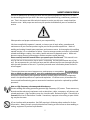
SAFETY PRECAUTIONS
These safety precauons are for protecon of safety and health. Failure to follow
these guidelines may result in serious injury or death. Be careful to read and follow all
cauons and warnings. Protect yourself and others.
Welding and cung processes produce high levels of ultraviolet (UV) radiaon that can cause se-
vere skin burn and damage. There are other potenal hazards involved with welding such as severe
burns and respiratory related illnesses. Therefore observe the following to minimize potenal acci-
dents and injury:
Use appropriate safety glasses with wrap around shields while in the work area, even under weld-
ing helmets to protect your eyes from ying sparks and debris. When chipping slag or grinding, gog-
gles and face shields may be required.
When welding or cung, always use an approved shielding device, with the correct shade of lter
installed. Always use a welding helmet in good condion. Discard any broken or cracked lters or
helmets. Using broken or cracked lters or helmets can cause severe eye injury and burn. Filter
shades of no less than shade 5 for cung and no less than shade 9 for welding are highly recommend-
ed. Shades greater than 9 may be required for high amperage welds. Keep lter lenses clean and
clear for maximum visibility. It is also advisable to consult with your eye doctor should you wear con-
tacts for correcve vision before you wear them while welding.
Do not allow personnel to watch or observe the welding or cung operaon unless fully protected
by a lter screen, protecve curtains or equivalent protecve equipment. If no protecon is availa-
ble, exclude them from the work area. Even brief exposure to the rays from the welding arc can
damage unprotected eyes.
Always wear hearing protecon because welding and cung can be extremely noisy. Ear protec-
on is necessary to prevent hearing loss. Even prolonged low levels of noise has been known to
create long term hearing damage. Hearing protecon also further protects against hot sparks and
debris from entering the ear canal and doing harm.
Always wear personal protecve clothing. Flame proof clothing is required at all mes. Sparks and
hot metal can lodge in pockets, hems and cus. Make sure loose clothing is tucked in neatly. Leather
aprons and jackets are recommended. Suitable welding jackets and coats may be purchased made
from re proof material from welding supply stores. Discard any burned or frayed clothing. Keep
clothing away from oil, grease and ammable liquids.
Leather boots or steel toed leather boots with rubber booms are required for adequate foot pro-
tecon. Canvas, polyester and other man made materials oen found in shoes will either burn or
melt. Rubber or other non conducve soles are necessary to help protect from electrical shock.
Flame proof and insulated gauntlet gloves are required whether welding or cung or handling met-
al. Simple work gloves for the garden or chore work are not sucient. Gauntlet type welding
gloves are available from your local welding supply companies. Never aempt to weld with out
gloves. Welding with out gloves can result in serious burns and electrical shock. If your hand or body
parts comes into contact with the arc of a plasma cuer or welder, instant and serious burns will oc-
cur. Proper hand protecon is required at all mes when working with welding or cung machines!

7
SAFETY PRECAUTIONS
WARNING! Persons with pacemakers should not weld, cut or be in the welding area
until they consult with their physician. Some pacemakers are sensitive to EMF radiation
and could severely malfunction while welding or while being in the vicinity of someone
welding. Serious injury or death may occur!
Welding and plasma cutting processes generate electro-magnetic fields and radiation.
While the effects of EMF radiation are not known, it is suspected that there may be
some harm from long term exposure to electromagnetic fields. Therefore, certain pre-
cautions should be taken to minimize exposure:
Lay welding leads and lines neatly away from the body.
Never coil cables around the body.
Secure cables with tape if necessary to keep from the body.
Keep all cables and leads on the same side the body.
Never stand between cables or leads.
Keep as far away from the power source (welder) as possible while welding.
Never stand between the ground clamp and the torch.
Keep the ground clamp grounded as close to the weld or cut as possible.
Welding and cutting processes pose certain inhalation risks. Be sure to follow any
guidelines from your chosen consumable and electrode suppliers regarding possible
need for respiratory equipment while welding or cutting. Always weld with adequate
ventilation. Never weld in closed rooms or confined spaces. Fumes and gases re-
leased while welding or cutting may be poisonous. Take precautions at all times.
Any burning of the eyes, nose or throat are signs that you need to increase ventilation.
Stop immediately and relocate work if necessary until adequate ventilation is ob-
tained.
Stop work completely and seek medical help if irritation and discomfort persists.
WARNING! Do not weld on galvanized steel, stainless steel, beryllium, titanium, cop-
per, cadmium, lead or zinc without proper respiratory equipment and or ventilation.
WARNING! This product when used for welding or cutting produces fumes and gas-
es which contains chemicals known to the State of California to cause birth defects
and in some cases cancer. (California Safety and Health Code §25249.5
et seq
.)
WARNING! Do not weld or cut around Chlorinated solvents or degreasing areas.
Release of Phosgene gas can be deadly. Consider all chemicals to have potential
deadly results if welded on or near metal containing residual amounts of chemicals.
Keep all cylinders upright and chained to a wall or appropriate holding pen. Certain
regulations regarding high pressure cylinders can be obtained from OSHA or local
regulatory agency. Consult also with your welding supply company in your area for
further recommendations. The regulatory changes are frequent so keep informed.
All cylinders have a potential explosion hazard. When not in use, keep capped and
closed. Store chained so that overturn is not likely. Transporting cylinders incorrectly
can lead to an explosion. Do not attempt to adapt regulators to fit cylinders. Do not
use faulty regulators. Do not allow cylinders to come into contact with work piece or
work. Do not weld or strike arcs on cylinders. Keep cylinders away from direct heat,
flame and sparks.

8
SAFETY PRECAUTIONS
continued
WARNING! Electrical shock can kill. Make sure all electrical equipment is properly grounded. Do
not use frayed, cut or otherwise damaged cables and leads. Do not stand, lean or rest on ground
clamp. Do not stand in water or damp areas while welding or cung. Keep work surface dry. Do not
use welder or plasma cuer in the rain or in extremely humid condions. Use dry rubber soled shoes
and dry gloves when welding or cung to insulate against electrical shock. Turn machine on or o
only with gloved hand. Keep all parts of the body insulated from work, and work tables. Keep away
from direct contact with skin against work. If ght or close quarters necessitates standing or resng
on work piece, insulate with dry boards and rubber mats designed to insulate the body from direct
contact.
All work cables, leads, and hoses pose trip hazards. Be aware of their locaon and make sure all
personnel in area are advised of their locaon. Taping or securing cables with appropriate restraints
can help reduce trips and falls.
WARNING! Fire and explosions are real risks while welding or cung. Always keep re exn-
guishers close by and addionally a water hose or bucket of sand. Periodically check work area for
smoldering embers or smoke. It is a good idea to have someone help watch for possible res while
you are welding. Sparks and hot metal may travel a long distance. They may go into cracks in walls
and oors and start a re that would not be immediately visible. Here are some things you can do to
reduce the possibility of re or explosion:
Keep all combusble materials including rags and spare clothing away from area.
Keep all ammable fuels and liquids stored separately from work area.
Visually inspect work area when job is completed for the slightest traces of smoke or embers.
If welding or cung outside, make sure you are in a cleared o area, free from dry tender and
debris that might start a forest or grass re.
Do not weld on tanks, drums or barrels that are closed, pressurized or anything that held amma-
ble liquid or material.
Metal is hot aer welding or cung! Always use gloves and or tongs when handling hot pieces of
metal. Remember to place hot metal on re-proof surfaces aer handling. Serious burns and injury
can result if material is improperly handled.
WARNING! Faulty or poorly maintained equipment can cause injury or death. Proper mainte-
nance is your responsibility. Make sure all equipment is properly maintained and serviced by qualied
personnel. Do not abuse or misuse equipment.
Keep all covers in place. A faulty machine may shoot sparks or may have exploding parts. Touching
uncovered parts inside machine can cause discharge of high amounts of electricity. Do not allow em-
ployees to operate poorly serviced equipment. Always check condion of equipment thoroughly
before start up. Disconnect unit from power source before any service aempt is made and for long
term storage or electrical storms.
Further informaon can be obtained from The American Welding Society (AWS) that relates directly
to safe welding and plasma cung. Addionally, your local welding supply company may have addi-
onal pamphlets available concerning their products. Do not operate machinery unl your are com-
fortable with proper operaon and are able to assume inherent risks of cung or welding.

9
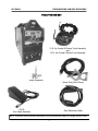
Introduction and Specifications Section 1
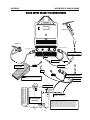
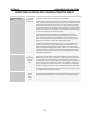
PowerTIG 210 EXT
12 ft. Air-Cooled 26 Series Torch Assembly
and
12 Ft. Air-Cooled 9 Series Torch Assembly
47K Ω
Foot Pedal Assembly
Heavy Duty Work Clamp
Argon Regulator
NOTE: Accessory and consumable appearance, style and quanty subject to change without noce.
Stick Electrode Holder

10
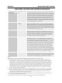
PowerTIG 210 EXT TIG/Sck Welder Specicaon
Process AC/DC GTAW-P/DC SMAW
Inverter Type Digital Microprocessor Controlled, IGBT Module
Minimum/Maximum Rated Output TIG (120) DC: 3 A/10.1 V– 120 A/15 V (240V) DC: 3 A/10.1 V-210 A/24 V
(120V) AC: 5 A/10.2 V– 120 A/15 V (240V) AC: 5 A/10.2 V– 210 A/24 V
Minimum/Maximum Rated Output Sck (120V) 20 A/20.8 V - 100 A/24V (240V) 20 A/20.8– 160 A/26.4 V
Start Type Solid State HF and Li Start
HF Point Gap Non-Adjustable Gapless Solid-State Design
TIG Duty Cycle @ Rated Amps/Volts (120V) 60% @ 125A/15V; 100%@ 80A/23.2V
(240V) 60% @ 210A/18.4V; 100%@170A/16.8V
Sck Duty Cycle @ Rated Amps/Volts (120V) 60% @ 100A/24V; 100% @ 80A/23.2V
(240V) 60% @ 160A/ 26.4V; 100% @ 130A/25.2V
OCV (U0) 70 V
Voltage Input (U1) 120/240V 50-60Hz 1 Phase
Maximum Inrush Amps (I1MAX) 110V: 27A; 220V: 31A
Maximum Operang Amps (I1EFF) 110V: 22A; 220V: 25A
Gas Pre-Flow /Post Flow Time 0-25 Seconds/ 0-50 Seconds
Start Amps/End Amps Start: (120V) 5-125A AC/DC ; (240V) 5-210A AC/DC
End: (120V ) 3-125A DC, 5-125A AC; (240V) 3-210V DC, 5-210V AC
Up/Down Slope 0-25/0-25 Seconds
AC Wave Forms Advanced Square, So Square, Triangular
AC Frequency Control 20-250 Hz
AC Balance Control 5-90% of Electrode Posive (EP +)
Pulse Frequency Hz (Pulses Per Second) .1-500 Hz DC
.1-250 Hz AC Advanced Square Wave (AC)
.1-10 So Square, Triangular (AC)
Pulse Amps (Rao) 5-99%
Pulse Time On (Balance) 5-100%
Sck Arc Force Control 0-100%
Sck Surge Amp Control (Hot Start Intensity) 0-100%
Sck Surge Amp Duraon (Hot Start Time) 0-2.0 Seconds
Minimum Water Ingress Protecon Standard IP21S
Eciency >/= 80%
Cooling Method Full Time High Velocity Fan with Tunnel design
Dimensions (approximate) 17.5” H X 9.25” W X 22” L
Weight (Bare Unit) 58lbs
AC Easy Start Parameters (Default) AC Frequency : 120Hz AC Balance: 25% Preow: .5 Post Flow: 4 Seconds Amps:
120 A (with pedal) Start amps: 50A End amps 50 A Upslope: 1 second,
Downslope: 3 seconds, (2T with torch switch)
DC Easy Start Parameters (Default) DC: Preow .5 Poslow: 3 Seconds Amps: 90 A (with pedal) Start amps: 50 A End
amps: 50A, Upslope: 1 second Downslope 3 seconds (2T with torch switch)
Minimum Generator Requirement* 120V: 4000 Was 240V: 7000 Was
Introduction and Specifications Section 1
* Generator must be cered as a clean power unit by its manufacturer with less than 10% total harmonic distoron.

11
General overview: The new 210EXT TIG/Sck welder
from Everlast is the latest in a new generaon of digi-
tal Pulse TIG/Sck inverter welders. With a digital mi-
croprocessor and IGBT module design, the welder
oers stable arc performance as well as convenient
setup and use. Key features include:
A. Siemens IGBT modules, a new 16 bit microproces-
sor and an overall plug and play design improve
reliability and reduces down me for service and
repair.
B. Full bridge design features so switching technolo-
gy which further extends IGBT component life and
extends its capabilies.
C. Solid state High Frequency design for arc starng
has improved arc iniaon at low amperages.
D. Features automac over-voltage, over current and
duty cycle protecon (over-heat) with self diagnos-
ing trouble code feature.
E. 9 Channel program memory stores favorite
sengs.
F. Arc force control and Hot Start me and Hot Start
intensity controls expand sck welding ability.
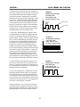
G. Four standard wave forms in AC oer increased
aluminum capability.
H. Advanced AC Pulse and Standard AC/DC pulse
increase weld capability on thin or heat sensive
materials.
I. Easy start-up feature oers simplied operaon.
General Use and Care: The welders are good for use
in many industrial environments such as ship yards,
fabricaon shops, pipelines. However, care should be
taken to keep the unit out of direct contact with water
spray. The unit is rated IP21S, which rates it for light
contact with dripping water. It is a good idea to re-
move the welder from the vicinity of any water or
moisture source to reduce the possibility of electrocu-
on or shock. Never operate in standing water.
Every 1-2 months, depending upon use, the welder
should be unplugged, opened up and carefully cleaned
with compressed air. Regular maintenance will extend
help extend the life of the unit.
IMPORTANT: Before opening the unit for any reason,
make sure the unit has been unplugged for at least 10
minutes to allow me for the capacitors to fully dis-
charge. Severe shock and/or death can occur.
Do not restrict air ow or movement of air around the
welder. Allow a buer distance of 2 from all sides if
possible, with a minimum distance of at least 18”. Do
not operate the welder immediately in the weld area
or the force of the fan will cause welding issues such as
unstable arc, or porosity.
Do not mount in areas that are prone to severe shock
or vibraon. Li and carry the welder by the handle.
Do not direct metallic dust or any dirt intenonally to-
ward the machine, parcularly in grinding and welding
operaons. Make sure the panel is protected from
damage while welding and cung operaons by ip-
ping down the clear protecve cover.
Duty Cycle. The duty cycle has been determined for
the 210 EXT. The duty cycle is rated for 60% at 210
Amps (TIG) in TIG mode. The duty cycle is based o a
10 minute duty cycle rang at 40° C. This means that
the unit is capable of being operated at the stated
amps for 6 out of every 10 minutes without a break for
cooling down the unit. This does NOT mean that the
210 EXT can work 60% of any other length of me. A
full 4 minute rest should be given to the welder for
maximum life. Sck duty cycle is rated at 35% for the
maximum rangs of sck at 160 amps for the 255EXT
and Overheat, over current, over voltage, and under
voltage faults are indicated by a warning light accompa-
nied with an error code. Do not operate the unit unl
the cause of the problem has been determined and
corrected. Do not shut down an overheated welder
unl it has safely cooled. Once the overheat condion
has been cleared, welding can resumed. Do not operate
the welder with the covers removed. In case of other
troubles follow the trouble diagnosis secon and/or call
Everlast Technical support.
This manual has been compiled to give an overview of
operaon and is designed to oer informaon cen-
tered around safe, praccal use of the welder. Weld-
ing is inherently dangerous. Only YOU, the operator of
this welder, can ensure that safe operang pracces
are followed, through the exercise of common sense
pracces and safety training. Do not operate this ma-
chine unl you have fully read the manual, including
points of safety. If you do not have the skill, and/or
knowledge to safely operate this welder, do not use
this welder unl formal training regarding safe opera-
on of this welder has been received.
Introduction and Specifications
Section 1
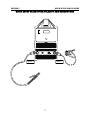
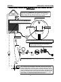
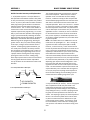
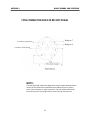
Figure 1. Basic Inverter design

12
!
WA
INPUT
OUTPUT
GAS (Ar)
CONTROL
WATER COOLER
(Oponal)
WATER-COOLED TORCH
GAS CONTROL
GAS (Ar)
WORK (+)
CONTROL
35 SERIES CONNECTOR
AIR-COOLED TORCH
CONTROL
FOOT PEDAL
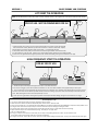
NOTE: Torch switch and foot pedal
control cannot be used at the same time.
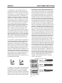
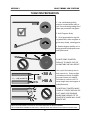
ARGON GAS LINE SHOULD BE TAGGED AS “Ar”. IF NOT, TAKE DRY, COM-
PRESSED AIR AND GENTLY BLOW THROUGH THE LINES TO DISCOVER
WHICH LINE EXHAUSTS THROUGH THE TORCH OR THROUGH THE RE-
TURN LINE. ON SOME TORCHES, THE WATER LINES ARE COLOR CODED:
BLUE FOR COOL WATER SUPPLY AND RED FOR HOT WATER RETURN.
COOLER FITTINGS SHOULD BE COLOR CODED BLUE AND RED AS WELL.
TORCH (+)
35 SERIES CONNECTOR
9/17 SERIES TORCH
26 SERIES TORCH
COOLANT IN (RED)
COOLANT OUT (BLUE)
QUICK SETUP AND USE GUIDE Section 2
QUICK SETUP GUIDE: TIG CONNECTIONS
18/20 SERIES TORCH
35 SERIES CONNECTOR

13
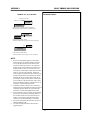
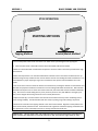
GAS CONTROL
WORK (-)
TORCH (+)
QUICK SETUP AND USE GUIDE Section 2
QUICK SETUP GUIDE: STICK POLARITY AND CONNECTIONS

14
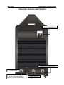
QUICK SETUP AND USE GUIDE Section 2
QUICK SETUP GUIDE: REAR CONNECTIONS AND WIRING 210 EXT
(US/Canada)
EVERLAST
NOTE: Use Ar or Ar/He only. Do not use more than 25% He in the Ar/He gas mix for best
arc starting and welding results. Too much helium in the mix may cause difficult starts.
CO2
NOTE: TO PREVENT STRAY HIGH FREQUENCY INTERFERENCE, THIS UNIT PROVIDES AN ADDI-
TIONAL GROUNDING POINT AT THE REAR OF THE UNIT. IT SHOULD BE DIRECTLY GROUNDED
THROUGH A SEPARATE WIRE TO AN OUTSIDE METAL ROD DRIVEN IN THE GROUND. THIS HELPS
PREVENT BLEEDBACK OF HF INTO THE POWER GRID, AND HELPS MUTE HF INTERFERENCE. ADDI-
TIONALLY, ALL SURROUNDING METAL OBJECTS SHOULD BE GROUNDED INCLUDING THE TABLE,
PIPES, WALLS ETC. TO PREVENT ELECTRICAL INTERFERENCE WITH OTHER CIRCUITS. DO NOT
COUPLE THIS WIRE TO THE GROUND PROVIDED IN THE ELECTRICAL CIRCUIT.
GAS INLET
AC 120V
110v/220 V
IMPORTANT: ALWAYS CONSULT A LICENSED ELECTRICIAN AND LOCAL CODES BEFORE
RE-WIRING YOUR WELDER OR ATTEMPTING TO MAKE ANY ELECTRICAL CONNECTION.
CLAMP
HF
Fe, Cu
NEMA 6-50P
L2,WHITE L1,BLACK; HOT
GREEN GROUND
120V/220V COOLER OUTLET. RECOMMENDED FOR DUAL VOLT-
AGE EVERLAST POWERCOOL WC 300 ONLY. WARNING: DO NOT
USE THIS OUTLET FOR ANY OTHER APPLICATION OR SERVICE!
SUPPLIED PLUG IS A NEMA 6-50P, THE STANDARD PLUG FOR MOST 1
PHASE 240 V WELDERS IN THE US AND CANADA. 120V OPERATION RE-
QUIRE S USE OF THE STEP-DOWN ADAPTER FOR 120 V OPERATION.
CONTACT EVERLAST TO PURCHASE AN ADAPTER IF NEEDED.
5/8” CGA FITTING
IMPORTANT: USE THE SUPPLIED 240V/120V ADAPTER FOR OPERATION
WITH 120V. DO NOT REMOVE THE NEMA 6-50 PLUG. NO INTERNAL
CHANGE IS REQUIRED TO OPERATE ON 120V. THIS UNIT AUTOMATICALLY
SENSES THE CHANGE IN SUPPLY POWER.
AC 220V

15
QUICK SETUP AND USE GUIDE Section 2
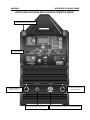
FRONT PANEL FEATURES AND CONTROLS POWERTIG 210EXT
GAS OUTLET CONTROL
1. CLEAR PROTECTIVE PANEL COVER
2. CONTROL PANEL
3.POSITIVE CONNECTOR
DINSE 35-70mm²
4.GAS OUTLET 9MM QUICK CONNECT 5. 7-PIN CONTROL FOR PEDAL/TORCH SWITCH/AMPTROL
6. NEGATIVE CONNECTOR
DINSE 35-70mm²

16
Section 2
FRONT PANEL FEATURES AND CONTROLS POWERTIG 210 EXT
QUICK SETUP AND USE GUIDE
POWERTIG 210EXT
MAIN PANEL FEATURES
PARAMETERS PURPOSE
1. Protecve Cover N/A Clear hinged cover protects panel from damage. Keep closed during welding opera-
ons.
2. Main Control Panel Digital The main control features digital adjustment. It oers features that include Easy Start
Up, Pulse, Advanced AC pulse, Sck welding feature, VRD Sck welding feature, Sck
Hot Start, Arc force control, Li start Tig, HF start TIG, 2T/4T/Pedal/Amptrol Control,
and error code diagnosis.
3. Posive Connector DINSE 35-70mm² Locaon of the posive terminal connecon. This is a standard 35 series connector.
For Sck: Torch Connecon (most electrodes). For TIG: Work Clamp Connecon.
4. Gas Outlet Quick Connect 9mm Connects the gas to the TIG torch. To connect: Push the torch ng into the connect-
or unl the collar slides forward with a click. To Release: Slide the outer collar back.
5. Control Connector 7 Pin
(Panasonic type)
Connect the foot pedal , amptrol or torch switch to this socket to control the welder.
Only one control connector can be plugged in at one me. If the torch has a torch
switch feature or hand amptrol feature, e the loose connector back or leave it hang-
ing while using the pedal.
6. Negave Connector DINSE 35-70mm² Locaon of the negave terminal connecon. This is a standard 35 series connector.
For Sck: Work clamp Cocnnecon. For TIG: Torch connecon.
NOTES:

17
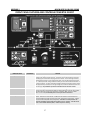
POWERTIG 210EXT PARAMETERS PURPOSE
1. Memory Funcon 1-9 The unit has 9 programs which allow the operator to select parameters then save the
sengs to the selected program channel. To operate, use the selector buon to select the
desired program number where the program is to be stored. The red select light will be lit,
indicang that the welder is in the programming mode. Enter the desired program parame-
ters. Aer all parameter changes have been made, press the selector buon and hold for 3
seconds and release. The green save buon will light, indicang the funcon has been saved.
Aer approximately 2 seconds, the save light will go out, and the unit will default back to the
red select light. Any addional adjustments made aer this will need to be resaved.
2. Pre-Flow 0-25 Seconds Pre-Flow sets the gas ow me before the arc starts aer the trigger or pedal is pressed.
Used to purge the torch and ood the weld area with shielding gas so the arc start is stable
and weld is free from porosity. Use enough me so that rst “blast” of argon is seled.
(about .3-.5 seconds) Pre-ow delays the arc start by the amount of me set.
3. Start Amps
5-250 A (AC/DC)
Serves as the 2T/4T beginning arc start amp value while using the torch switch, pedal or
amptrol. Allows the arc to be started at a dierent value than the selected maximum or
minimum welding amps while using the torch switch, foot pedal or hand amptrol. Typically
used to start the weld puddle more quickly/slowly. This feature is usually turned to the
minimum amp seng (5 amps) while the foot pedal is in use. However, It can be used to
create a “hot” TIG start with the pedal, or used to improve arc starng.
QUICK SETUP AND USE GUIDE Section 2
FRONT PANEL FEATURES AND CONTROLS POWERTIG 210EXT
1
2
3
4
5
6
7
8 9
10
11
12 13
15a
15b
16
17
18
19
20
21
24
22
23
14

18
POWERTIG 210 EXT PARAMETERS PURPOSE
4. Upslope 0-25 Seconds Upslope ramps amps “up” from the start amp value to the welding amp value while
starng the weld puddle. For best operaon, value should be set to 0 with foot pedal in
use. If used with an hand amptrol, without a separate switch to control slope in 2T/4T
mode, then the upslope should be also be set to 0. If slope is set while in use with the foot
pedal, sluggish or slow amp acceleraon aer the arc is struck will result.
5. Welding Amps AC: 5-210 Amps
DC: 3-210 Amps
Welding amps dene the top limit of amps at which the machine has been programmed to
operate. Used with the foot pedal and amptrol, this is the maximum liming value at the
upper limit of the range of travel. With the torch switch this is the desnaon, or maxi-
mum current reached aer up slope has occurred. When used with pulse, Welding Amps
represents the high amp stage of the pulse cycle. When used with Advanced AC Pulse,
this represents the AC, high amp stage of the pulse.
6. Pulse Time On (Balance) 5-100% of Welding
Amp (Peak) Time
Denes the duty cycle (balance) of the pulse, by dividing or skewing the amount of me
the pulse stays in the lower or upper stage of the pulse. The pulse consists of two stages:
Welding amps (upper /Peak) and Pulse amps (lower/background current). This is repre-
sented by a % of total me the pulse spends in the pulse amp stage of the cycle during one
full pulse. The feature can be used to increase or decrease pulse amp me relave to the
welding amp me of the cycle to help manage heat input. This funcons the same in both
Standard and Advanced AC pulse modes.
7. Pulse Amps (%) 3-100% of
Welding amps
Governs the lower( base or background current) amp value during the pulse cycle as a
percent of welding amps. In Advanced AC Pulse mode this also represents the DC—
(negave) low amp stage of the pulse cycle.
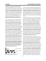
8. Pulse Frequency , Hertz
(Pulses per second )
DC:
.1-500 Hz
AC Advanced Square.:
.1-250Hz
AC So Square:
.1-10 Hz
AC Triangular:
.1-10 Hz
Advanced AC Pulse:
.1-10 Hz
Represented by Hertz (Hz), the pulse frequency denes the actual number of mes each
second the pulse makes one complete cycle between welding amps (peak/high amp value)
and pulse amps (background/low amp value). This is also commonly referred to as Pulses
Per Second (PPS). Low pulse frequencies are ideal for ming the point where ller metal is
added. This helps improve appearance and uniformity. Higher pulse frequencies are use-
ful for welding seams and edges of thin material. Also it is useful for overall heat input
control for thicker metals. Higher pulse frequencies are highly useful for automated weld-
ing processes. WARNING: WELDING AT HIGH PULSE FREQUENCIES INCREASES THE DECI-
BEL /NOISE LEVEL OF THE ARC. HEARING PROTECTION IS HIGHLY RECOMMENDED!
In Advanced mode, the funcon of the frequency is essenally the same, and represents
the number of mes per second that the welder cycles completely between AC (Welding
Amps/Peak current) and DC- (Pulse amps/base current).
9. AC Frequency 20-250 Hz Governs the number of mes per second that the current alternates in AC mode. To
achieve greater arc focus (constricon) and increase puddle agitaon while welding in AC
mode, increase AC frequency. This allows pinpoint use on thin materials, and helps pene-
traon on thicker materials. Ideal adjustment range is usually between 100-150 Hertz. For
comparison most transformer welders in the US operate on 60 Hz. Greater arc control and
stability can be achieved through the higher frequency range oered by this welder.
Lower Frequencies will widen and soen the arc and reduce the level of control. WARN-
ING: INCREASING THE AC FREQUENCY ALSO INCREASES THE DECIBEL/NOISE LEVEL OF
THE AC WELDING ARC. HEARING PROTECTION SHOULD BE WORN!
10. AC Balance 5-90% of EP Denes the percent of Electrode Posive (EP) used during AC welding to provide cleaning
acon. This divides the me that the AC cycle spends in Electrode Posive or Electrode
Negave during one full AC cycle. It controls the amount of cleaning and penetraon via
a rao to achieve the best balance while welding on AC. Too much cleaning acon will
result in tungsten balling or spling. Too lile cleaning can result in dirty, sooty welds
and even a dull weld appearance. Simply put, as the percent increases, greater cleaning
will occur, but less penetraon will be achieved. NOTE: This is expressed as a percent of
full Electrode Posive polarity. This unit uses 100% Electrode Posive as the reference,
which is opposite (a reciprocal value) from some brands of TIG welders with this adjust-
ment. Using the welder in excess of 50% EP can ball and vaporize the tungsten. For
most welds, no more than 45% cleaning is needed. Ideally, start with 30% EP for a refer-
ence point, and ne tune the cleaning by adjustment this point in increments of 5%.
QUICK SETUP AND USE GUIDE Section 2
FRONT PANEL FEATURES AND CONTROLS POWERTIG 210EXT

19
POWERTIG 210EXT PARAMETERS PURPOSE
11. Down Slope 0-25 Seconds Down Slope will ramp amps “down” from the welding amp value to the end amp value to
give me to ll the crater le at the end of the weld bead. For best operaon, value should
be set to 0 with foot pedal in use. If used with a hand amptrol, without a separate switch to
control slope in 2T/4T mode, then the upslope should be set to 0 as well. When using the
foot pedal or amptrol without a separate control switch, the arc may are at the end of the
weld aer the weld has been lowered to the minimum amp level if the value has not been
set to 0. Can also be used in the 4T mode to help with heat control by briey tapping the
switch to cool o the weld before tapping it again to restart the up slope sequence before
the arc reaches the end amp stage.
12. End Amps AC: 5-250 Amps
DC: 3-250 Amps
Sets the nal or minimum current before the arc is terminated. Used for lling craters at the
ends of the weld and crack prevenon. When using the foot pedal, this should be set to the
lowest amp value (3 for DC; 5 for AC) or arc may suddenly get hot at the end of the weld.
13. Post Flow 0-50 Seconds Controls the amount of me in seconds that the argon ows aer the arc has terminated.
Provides proper shielding during cooling to prevent rapid oxidaon of the weld which results
in porosity. Use 1-2 seconds post ow me for every 10 amps.
14. Purge Gas N/A Used to purge gas from lines or set gas ow without using torch switch or foot pedal or foot
pedal. Allows gas to ow connuously unl it is shut o.
15a. HF TIG/ Li TIG/Sck/
VRD Sck Process Selector
N/A This selects TIG or sck mode. It also selects the type of TIG start. The Process selector
oers the choice of Li Tig (for DC only) which requires contact with the metal to iniate the
arc and High Frequency Start which allows non contact starng of the arc (for AC and DC).
When in HF mode, the unit relies upon a gapless solid state HF module to start the arc, which
is a more reliable and trouble free design than tradional point gap HF design. The li start
funcon on the EXT models provides a cold electrode for safety, and prevents accidental
starts. This requires that the pedal or torch switch must be used to energize the arc. HF
refers to the start type only. The inverter design of the welder eliminates the need for a
constant HF overlay in AC.
15b. HF TIG/ Li TIG/Sck/
VRD Sck Process Selector
N/A This selects the sck process or the VRD sck process. A Voltage Reducon Devices (VRD) is
required in some situaons to reduce the risk of electrocuon. The VRD reduces the Open
Circuit Voltage (OCV) below 20 volts (±3V) for safer operaon unl the arc is struck and low
resistance is sensed. The VRD can make starng more dicult in some situaons, and re-
quires a brief contact with the metal to start the weld. Rusty metals, or painted surfaces may
make starng more dicult by oering too high of a resistance value for the unit to sense an
arc strike aempt. When using the VRD Sck mode, a slight delay in arc starng may be
noced. A rm scratching acon may be necessary.
16. Parameter Selector N/A The push buon selector is used to scroll le to right through dierent panel sengs.
17. Parameter Adjuster N/A The control knob is used increase or decrease parameter values. To increase adjustment
speed, push in on the knob while turning.
18. Arc Force Control (DIG) 0-100% Controls the arc response when an arc is held short and voltage begins to drop. Arc force
automacally compensates by modifying the volt/amp curve to maintain the energy needed
to weld. Represented as a percent of available arc force amperage.
19. Hot Start Time
(Surge Amp Time)
0-2 Seconds Sets the length of me that the Hot Start is acve while starng the arc. Used to reduce
scking of the electrode during the arc strike phase.
20. Hot Start Amps % 0-100% Controls the “hot” start amperage during the inial contact of the electrode. It makes arc
starng easier by sending a surge of amps briey while arc is struck to prevent scking. The
% represents the percent of addional hot start amps available.
21. TIG Pulse Mode Selector Pulse OFF
Standard Pulse
Advanced AC Pulse
The unit features two pulse modes. The standard mode is available in AC and DC modes. The
Advanced AC mode, works only in AC. Pulse is used to control heat input on metals by puls-
ing amperage between a high (Peak) and low (Base or background) amp value. The high amp
stage is represented as Welding Amps. The low amp stage is represented as Pulse Amps. The
Advanced AC pulse pulses between AC and DC– polarity to control heat input on thin alumi-
num. In advanced mode, AC is assigned the welding amps stage of the pulse, and DC– is
assigned the pulse amps stage of the pulse. Both the standard and Advanced pulse modes
have the same features of pulse me on, pulse frequency and pulse amps. Other than
changing the polarity in Advanced AC pulse mode, the two pulses are similar in adjustment.
QUICK SETUP AND USE GUIDE Section 2
FRONT PANEL FEATURES AND CONTROLS POWERTIG 210EXT

20
POWERTIG 210 EXT PARAMETERS PURPOSE
22. 2T/4T/ Pedal/Amptrol
Selector
2T, 4T, Pedal,
Pedal with 2T,
Pedal with 4T
This selects the operaon of the torch switch, pedal, or hand amptrol.
To operate with the torch switch, select 2T or 4T. For 2T operaon, simply press and hold the
switch. The panel program will cycle automacally. When the switch is released, the arc will
downslope and terminate with post gas ow. When in 4T mode, the switch is pressed, and
held to start the pre-ow and the start amps part of the cycle. When released, upslope be-
gins and connues unl the amps are raised to the preset welding amps. When pressed and
held again, downslope starts and ramps down to the end amp stage (crater current). When
released, the arc terminates, and post ow begins. If desired, before the downslope nishes,
the switch may be tapped again to start the up slope again.
To operate with the foot pedal, select pedal mode. The features such as start amps,
upslope, down slope, and end amps will funcon with the pedal. Be sure to lower these
features to the minimum values when the foot pedal is in use, unless a desired eect is
needed. The start amp feature can be parcularly useful as a brief “hot start” g seng
which provides an inial burst of amps to be to rapidly develop a puddle.
To operate with a hand amptrol, select Pedal, and then press the selector addionally to
select the 2T or 4T feature light. Both the Pedal and the 2T or 4T pedal will be lit. The
starng and ending of the arc will be the same as the standard 2T or 4T mode, except the
amps can be adjusted while welding with the amptrol. However, some amptrols have only a
a switch that is built into the amptrol mechanism, and is not controllable independently of
the amperage. When this type of amptrol is used, the unit should be placed into standard
pedal mode for proper operaon.
23. AC Waveform/DC selector DC
AC
Advanced Square
So Square
Triangular
Sine
The unit features AC/DC operaon, with 4 standard wave forms available in AC for specialized
welding needs. The advanced square wave is the default mode and is the best all around
mode with excellent wet in, and arc controllability . So Square wave and Sine wave mimic
the feel and eect of the transformer welders. The So square wave is similar to Square
wave transformers, and have a smooth, buery feel, but maintains good control over the arc.
The Sine wave is similar to much older sine wave transformer TIG welders. This oers the
soest arc, and aords less control than other modes. The Triangular wave is designed for
rapid wet in, and high speed travel on the metal. It also features rapid freeze of the puddle.
DC mode is the standard mode used for all metals except aluminum and magnesium. Alumi-
num and Magnesium should be welded in AC only.
24. Data Indicator Amps
Seconds
Percent
Hertz
Warning
On
The unit features a single main display. The data in the display is always accompanied by a
corresponding LED light which indicates the funcon being represented. This also includes a
self diagnosing funcon which displays an error code and a corresponding warning light.
QUICK SETUP AND USE GUIDE Section 2
FRONT PANEL FEATURES AND CONTROLS POWERTIG 210EXT
Page is loading ...
Page is loading ...
Page is loading ...
Page is loading ...
Page is loading ...
Page is loading ...
Page is loading ...
Page is loading ...
Page is loading ...
Page is loading ...
Page is loading ...
Page is loading ...
Page is loading ...
Page is loading ...
Page is loading ...
Page is loading ...
Page is loading ...
-
 1
1
-
 2
2
-
 3
3
-
 4
4
-
 5
5
-
 6
6
-
 7
7
-
 8
8
-
 9
9
-
 10
10
-
 11
11
-
 12
12
-
 13
13
-
 14
14
-
 15
15
-
 16
16
-
 17
17
-
 18
18
-
 19
19
-
 20
20
-
 21
21
-
 22
22
-
 23
23
-
 24
24
-
 25
25
-
 26
26
-
 27
27
-
 28
28
-
 29
29
-
 30
30
-
 31
31
-
 32
32
-
 33
33
-
 34
34
-
 35
35
-
 36
36
-
 37
37


Everlast POWERTIG 210 EXT User manual
- Category
- Welding System
- Type
- User manual
Ask a question and I''ll find the answer in the document
Finding information in a document is now easier with AI
Related papers
-
Everlast PowerTig 200DX-DV User manual
-
-
-
-
-
-
-
-
-
Other documents
-
VEVOR MMA-140 User manual
-
 Reboot WELDING MACHINE User manual
-
 WeldCorp WCPC001 Owner's Operating Manual
-
 Lotos LTPDC2000D User manual
-
VEVOR AC.DC TIG-200 User manual
-
-
Lincoln Electric Aspect 375 Quick Reference Manual
-
 S7 CUT50 Owner's manual
-
ESAB TIG 160S Inverter Arc Welder User manual
-
Nova NVA-FT06 Wireless TIG Foot Pedal User manual


