Page is loading ...

Inver ter Powered 200iDV AC/DC TIG
OWNER’S MANUAL
04/2018
WARNING:
Read carefully and understand all ASSEMBLY AND OPERATION
INSTRUCTIONS before operating. Failure to follow the safety rules and other
basic safety precautions may result in serious personal injury.

Page of 33
2
WARRANTY
METAL MAN WORK GEAR CO
EFFECTIVE JANUARY 1, 2013
LIMITED WARRANTY
This warranty applies to the original purchaser and is subject to the terms and conditions listed below. This Limited Warranty is for
new equipment sold after the above date, providing coverage for defects in material and workmanship at the time it is shipped from
the factory.
Limited to the warranty periods below, Metal Man Work Gear Co will repair or replace the item under warranty that fails due to
defects in material and workmanship. Metal Man Work Gear must be notified within 30 days of the failure, so as to provide
instructions on how to proceed with the repair of your welder and warranty claim processing. Warranty period begins at the time the
welder is purchased from and Authorized Reseller of Metal Man Work Gear Co. products. Keep your receipt as proof of
purchase.
Warranty Periods
Limited Warranty is divided into three categories. No Warranty, 90 days and 3 year.
No Warranty
Normal wear items, MIG gun parts (contact tips, nozzle, contact tip adapter, MIG gun liner), drive roll, electrode holder, ground
clamps, Plasma torch parts (nozzle, electrode, diffuser, cover) and TIG torch parts (collet, collet body, tungsten, backcap) are
considered consumable items and are not covered under warranty.
90 days
Parts for Metal Man Work Gear welding carts and welding cabinets. This warranty covers the absence of or defective parts.
3 year
This 3 year warranty covers parts and Labor on items such as: transformer, reactor, rectifier, solenoid valve, PC Board, switches,
controls, gas valve, drive motor, drive system other than drive roll and any other component that requires the removal of the sheet
metal to access. Any shipping related to warranty repair is the responsibility of the customer.
Voiding Warranty
Warranty does not apply to: Shipping Damage, Misuse and abuse of the unit, alteration of the unit in any way.
Warranty Claim
This is a parts and labor warranty. Do not return your unit to the retailer you purchased it from. Retain your receipt in the case
a warranty claim is needed. No warranty will be provided without the original receipt from an authorized reseller of Metal Man Work
Gear Products. To make a warranty claim, call our welder help line at 888-762-4045, M-F 8:00 am to 5:00 PM Central time or email
sales@metalmangear.com.

Page of 33
3
GENERAL SAFETY RULES
WARNING: Read and understand all instructions. Failure to follow all instructions listed
below may result in serious injury.
CAUTION: Do not allow persons to operate or assemble this Flux Core 125 until they
have read this manual and have developed a thorough understanding of how the Flux Core
125 works.
WARNING: The warnings, cautions, and instructions discussed in this instruction
manual cannot cover all possible conditions or situations that could occur. It must be
understood by the operator that common sense and caution are factors which cannot be built into
this product, but must be supplied by the operator.
SAVE THESE INSTRUCTIONS
IMPORTANT SAFETY CONSIDERATIONS
1.1 Your Welding Environment
-Keep the environment you will be welding in free from flammable materials.
-Always keep a fire extinguisher accessible to your welding environment.
-Always have a qualified person install and operate this equipment.
-Make sure the area is clean, dry and ventilated. Do not operate the welder in humid, wet or poorly
ventilated areas.
-Always have your welder maintained by a qualified technician in accordance with local, state and
national codes.
-Always be aware of your work environment. Be sure to keep other people, especially children,
away from you while welding.
-Keep harmful arc rays shielded from the view of others.
-Mount the welder on a secure bench or cart that will keep the welder secure and prevent it from
tipping over or falling.
1.2 Your Welder’s Condition
-Check ground cable, power cord and welding cable to be sure the insulation is not damaged.
Always replace or repair damaged components before using the welder.
-Check all components to ensure they are clean and in good operating condition before use.
1.3 Use of Your Welder
Do not operate the welder if the output cable, electrode, torch, wire or wire feed system is wet. Do
not immerse them in water. These components and the welder must be completely dry before
attempting to use them.
-Follow the instructions in this manual.
-Keep welder in the off position when not in use.
-Connect ground lead as close to the area being welded as possible to ensure a good ground.

Page of 33
4
-Do not allow any body part to come in contact with the welding wire if you are in contact with the
material being welded, ground or electrode from another welder.
-Do not weld if you are in an awkward position. Always have a secure stance while welding to
prevent accidents. Wear a safety harness if working above ground.
-Do not drape cables over or around your body.
-Wear a full coverage helmet with appropriate shade (see ANSI Z87.1 safety standard) and safety
glasses while welding.
-Wear proper gloves and protective clothing to prevent your skin from being exposed to hot metals,
UV and IR rays.
-Do not overuse or overheat your welder. Allow proper cooling time between duty cycles.
-Keep hands and fingers away from moving parts and stay away from the drive rolls.
-Do not point MIG gun at any body part of yourself or anyone else.
-Always use this welder in the rated duty cycle to prevent excessive heat and failure.
1.4 Specific Areas of Danger, Caution or Warning
Electrical Shock
Electric arc welders can produce a shock that can cause injury or death. Touching
electrically live parts can cause fatal shocks and severe burns. While welding, all metal
components connected to the wire are electrically hot. Poor ground connections are a hazard, so
secure the ground lead before welding.
-Wear dry protective apparel: coat, shirt, gloves and insulated footwear.
-Insulate yourself from the work piece. Avoid contacting the work piece or ground.
- Do not attempt to repair or maintain the welder while the power is on.
-Inspect all cables and cords for any exposed wire and replace immediately if found.
-Use only recommended replacement cables and cords.
-Always attach ground clamp to the work piece or work table as close to the weld area as possible.
-Do not touch the welding wire and the ground or grounded work piece at the same time.
-Do not use a welder to thaw frozen pipes.
Fumes and Gases
-Fumes emitted from the welding process displace clean air and can result in injury or
death.
-Do not breathe in fumes emitted by the welding process. Make sure your breathing air is clean and
safe.
-Work only in a well-ventilated area or use a ventilation device to remove welding fumes from the
environment where you will be working.
-Do not weld on coated materials (galvanized, cadmium plated or containing zinc, mercury or
barium). They will emit harmful fumes that are dangerous to breathe. If necessary use a ventilator,
respirator with air supply or remove the coating from the material in the weld area.
-The fumes emitted from some metals when heated are extremely toxic. Refer to the material safety
data sheet for the manufacturer’s instructions.
-Do not weld near materials that will emit toxic fumes when heated. Vapors from cleaners, sprays
and degreasers can be highly toxic when heated.
UV and IR Arc Rays
The welding arc produces ultraviolet (UV) and infrared (IR) rays that can cause injury to

Page of 33
5
your eyes and skin. Do not look at the welding arc without proper eye protection.
-Always use a helmet that covers your full face from the neck to top of head and to the back of each
ear.
-Use a lens that meets ANSI standards and safety glasses. For welders under 160 Amps output,
use a shade 10 lens; for above 160 Amps, use a shade 12. Refer to the ANSI standard Z87.1 for
more information.
-Cover all bare skin areas exposed to the arc with protective clothing and shoes. Flame-retardant
cloth or leather shirts, coats, pants or coveralls are available for protection.
-Use screens or other barriers to protect other people from the arc rays emitted from your welding.
-Warn people in your welding area when you are going to strike an arc so they can protect
themselves.
Fire Hazards
Do not weld on containers or pipes that contain or have had flammable, gaseous or liquid
combustibles in them. Welding creates sparks and heat that can ignite flammable and
explosive materials.
-Do not operate any electric arc welder in areas where flammable or explosive materials are
present.
-Remove all flammable materials within 35 feet of the welding arc. If removal is not possible, tightly
cover them with fireproof covers.
-Take precautions to ensure that flying sparks do not cause fires or explosions in hidden areas,
cracks or areas you cannot see.
-Keep a fire extinguisher close in the case of fire.
-Wear garments that are oil-free with no pockets or cuffs that will collect sparks.
-Do not have on your person any items that are combustible, such as lighters or matches.
-Keep work lead connected as close to the weld area as possible to prevent any unknown,
unintended paths of electrical current from causing electrical shock and fire hazards.
-To prevent any unintended arcs, cut wire back to ¼" stick out after welding.
Hot Materials
Welded materials are hot and can cause severe burns if handled improperly.
-Do not touch welded materials with bare hands.
-Do not touch MIG gun nozzle after welding until it has had time to cool down.
Sparks/Flying Debris
Welding creates hot sparks that can cause injury. Chipping slag off welds creates flying
debris.
-Wear protective apparel at all times: ANSI-approved safety glasses or shield, welder’s hat and ear
plugs to keep sparks out of ears and hair.

Page of 33
6
Electromagnetic Field
-Electromagnetic fields can interfere with various electrical and electronic devices such as
pacemakers.
-Consult your doctor before using any electric arc welder or cutting device
-Keep people with pacemakers away from your welding area when welding.
-Do not wrap cable around your body while welding.
-Wrap MIG gun and ground cable together whenever possible.
-Keep MIG gun and ground cables on the same side of your body.
Shielding Gas Cylinders Can Explode
High pressure cylinders can explode if damaged, so treat them carefully.
-Never expose cylinders to high heat, sparks, open flames, mechanical shocks or arcs.
-Do not touch cylinder with MIG gun.
-Do not weld on the cylinder
-Always secure cylinder upright to a cart or stationary object.
-Keep cylinders away from welding or electrical circuits.
-Use the proper regulators, gas hose and fittings for the specific application.
-Do not look into the valve when opening it.
-Use protective cylinder cap whenever possible
1.5 Proper Care, Maintenance and Repair
-Always have power disconnected when working on internal components.
- Do not touch or handle PC board without being properly grounded with a wrist strap. Put PC board
in static proof bag to move or ship.
-Do not put hands or fingers near moving parts such as drive rolls of fan
USE AND CARE
Do not modify this unit in any way. Unauthorized modification may impair the function and/or
safety and could affect the life of the equipment. There are specific applications for which the
this unit was designed.
Always check of damaged or worn out parts before using this unit. Broken parts will affect
the unit’s operation. Replace or repair damaged or worn parts immediately.
Store idle. When this unit is not in use, store it in a secure place out of the reach of children.
Inspect it for good working condition prior to storage and before re-use.

Page of 33
7
TECHNICAL SPECIFICATIONS
Item
Specification
Power Supply
120V, 20A, 50/60 Hz, Single Phase
230V, 35A, 50/60 Hz, Single Phase
Output No Load Voltage
65V
Rated Duty Cycle
35% @ 200A
DC TIG Output Range
10 - 95A with 120V Input Power
10 - 200A with 230V Input Power
AC TIG Output Range
20 - 95A with 120V Input Power
20 - 200A with 230V Input Power
Stick Welding Output Range
20 - 65A with 120V Input Power
20 - 160A with 230V Input Power
Pulse Frequency
0.2 - 200 HZ
AC Arc Frequency
50 to 150 HZ
AC Arc Balance Control
50% to 85% EN
Weight
37-1/2 lbs.
Dimension L×W×H
19.75 in. x 9.5 in. x 16.125 in.
DESCRIPTION
The Metal Man Inverter Powered 200iDV AC/DC TIG is a dual voltage, inverter powered AC and DC TIG,
Pulse TIG and DC Stick welder. This unit is intended to be used on a 50 amp 230V AC circuit or 120V,
20A AC Circuit, without the use of an extension cord. This machine comes complete with a TIG Torch, a
Foot Pedal, regulator/flowmeter with inert gas hose, a ground cable and clamp, and an Electrode Holder
with cable.
The 200iDV AC/DC TIG is the ideal Stick and TIG welder for every shop. The DC stick mode allows you
to stick weld when your application requires it. In the DC TIG mode you are able to TIG weld metals such
as steel and stainless steel. In the AC TIG mode, you are able to TIG weld non-ferrous metals such as
Aluminum. This unit is equipped with advanced TIG capabilities including Pulse, AC Arc Frequency
Control, AC Arc Balance Control, and Auto Balance/Frequency Control. The advanced inverter
technology that powers the 200iDV AC/DC provides for better arc control, lower power consumption, in a
lighter more portable unit.
DIGITAL METERS
Digital meters display welding amperage and voltage while welding.
FUNCTIONAL CONTROL
Use the Functional Control dial to increase and decrease the value of the function you are setting. An
indicator light will then illuminate showing which function you are setting.
WELD PARAMETER SETTING INDICATORS
When the push button below this set of indicators lights is pushed, the operator can sequence through
the different welding parameters. Use the Functional control to adjust the parameter setting indicated on
the digital meters.
REMOTE FOOT PEDAL CONTROL
The foot pedal is used to start the arc and manually adjust the amperage while TIG welding. The
cord will attached to the 5-Pin connector on the front of the unit.
STYLE 26 TIG TORCH
The TIG torch transfers welding power from the welding power source to the tungsten for the
purpose of TIG welding. It also delivers the shielding gas from the welding power source to the
welding zone. This style 26 torch uses the same common parts as other Style 26 TIG torches

Page of 33
8
GROUND CABLE AND CLAMP
The ground cable and clamp are attached to the work piece to complete the circuit allowing the flow
of current needed to weld.
REGULATOR/FLOWGAUGE AND GAS HOSE
The regulator nstalls directly on the shielding gas cylinder. Required for TIG welding. The regulator
controls the compressed gas and allows you to adjust the flow rate of the gas. The gas hose
connects to the regulator/flowgauge and delivers the shielding gas from the shielding gas bottle to
the welder.
ELECTRODE HOLDER AND CABLE
The electrode holder and weld cable transfers welding power from the welding power source to the
electrode for the purpose of stick welding.
WELD PROCESS INDICATORS
When the push button below this set of indicators lights is pushed, the operator can sequence through
the different welding processes.
INDICATOR LIGHTS
The indicator lights can be used to help with troubleshooting the welder. When the power indicator light is
on, input power is supplied to the main transformer and control circuit. When the work indicator is on, it is
indicating welding current is activated. When the temperature indicator is on, the machine has gone into
protection mode and requires the internal temperature to cool. When the power protection light is on, the
machine has gone into protection mode and requires that the input voltage stabilize to within 15% of the
rated input voltage.
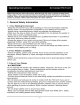
Electrode Holder
And Cable
Digital
Meters
Indicator
Lights
Weld Process
Indicators
Electrode Holder
And Weld Cable
Regulator/Flowgauge
With Gas Hose
Weld Parameter
Setting Indicators
Remote Foot
Pedal Control
TIG Torch
Functional
Control

Page of 33
9
ASSEMBLY
Electrical Shock Can Kill!
High voltage danger from power source! Consult a qualified electrician for proper installation
of receptacle. This welder must be grounded while in use to protect the operator from
electrical shock.
Do not remove grounding prong or alter the plug in any way. Use only the supplied adapter
between the welder's power cord and the power source receptacle. Make sure the POWER
switch is OFF then connect your welder's power cord to a properly grounded 230 VAC (220V
- 240V), 60 HZ, single phase, 50 amp power source. If operating on 120V, attach the 120V
Adapter cord to the unit power cord and then connect the assembly to a properly grounded
120 VAC (110V-130V), 60 Hz, single phase, 20 amp power source.
1. POWER REQUIREMENT 230V - AC single phase 230V (220-240V) 50/60 HZ fused with a 50 amp
time delayed fuse or circuit breaker is required. DO NOT OPERATE THIS UNIT if the ACTUAL power
source voltage is less than 215 volts AC or greater than 240 volts AC.
2. POWER REQUIREMENT 120V - AC single phase 120V (110-130V) 50/60 HZ fused with a 20 amp
time delayed fuse or circuit breaker is required. DO NOT OPERATE THIS UNIT if the ACTUAL power
source voltage is less than 110 volts AC or greater than 130 volts AC.
a. When connecting this unit to 120V power, connect the 120V adapter cord to the power
cord pigtail that is attached to the machine.
3. EXTENSION CORD - We do not recommend an extension cord because of the voltage drop they
produce. This drop in voltage can affect the performance of the welder. If you need to use an extension
cord, we recommend you check with a qualified electrician and your local electrical codes for your
specific area. Do not use an extension cord over 25 ft. in length.
4. STICK WELDING CONNECTION – DC Stick welding is generally performed DC Electrode Positive.
That means that the electrode holder and cable would be attached to the Positive (+) weld output
connection and the ground cable and clamp would be attached to the Negative (-) weld output
connection.
Positive (+) Weld
Output Connection
Negative (-) Weld
Output Connection

Page of 33
10
5. TIG WELDING CONNECTION – DC TIG welding is generally performed DC Electrode negative. That
means that the TIG torch and cable would be attached to the Negative (-) weld output connection and the
ground cable and clamp would be attached to the Positive (+) weld output connection. Use this same
connection when AC TIG welding. Connect the Remote Foot Pedal to the Remote connection on the
lower front panel. Connect the TIG torch gas supply line to the Gas Outlet on the lower front panel.
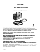
6. BACK PANEL CONNECTIONS
Remote Foot
Pedal Connection
TIG Torch
Gas Connection
Power Cord
Power
Switch
Shielding Gas
Connection

Page of 33
11
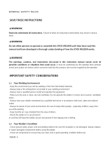
7. GAS INSTALLATION
Shielding gas cylinders and high pressure cylinders can explode if damaged, so treat them
carefully.
Never expose cylinders to high heat, sparks, open flames, mechanical shocks or arcs.
Do not weld on the cylinder.
Always secure cylinder upright to a cart or stationary object.
Keep cylinders away from welding or electrical circuits.
Use the proper regulators, gas hose and fittings for the specific application.
a. Connect one end of the gas hose to the gas hose connection on the back of the welder. Use a
wrench to snug up the connection.
b. Connect the other end of the gas hose to the gas hose connection on the supplied rear mount
regulator/flowgauge. Use a wrench to snug up the connection.
c. Before installing the regulator, it is good practice to make certain no debris is in the gas bottle
connection. Rotate the bottle so the gas connection is not pointing toward you or any other
person. Turn the valve on the gas bottle clockwise and quickly close. This quick thrust of gas will
clear any debris in the connection. Connect the regulator to the gas bottle connection. Use a
wrench to snug up the connection.
(1) Gas Bottle Valve
(2) Gas Flow Gauge (Set at 20 CFH)
(3) Gas Pressure Gauge
(4) Regulator
(5) Gas Flow Adjuster
(6) Gas Hose Connection
(7) Gas Cylinder
d. Open the Gas Bottle Valve on the cylinder of gas.
e. Turn the Gas Flow Adjuster on the regulator so that the gas flow rate is set at approximately 20
CFH. Make certain you are reading the correct scale on the gauge.
NOTE: Slowly open the cylinder valve by turning it counterclockwise until the cylinder pressure gauge
registers on the first gauge of the regulator. Turn the adjustment knob clockwise (right) slowly to increase
gas flow to 20 CFH. To reduce the gas flow turn the adjustment counterclockwise (left). The gas valve
is located on the back panel of the welder and activated by the remote control. Gas flow should be
1
7
4
3
2
6
5

Page of 33
12
heard when the remote is activated. No gas flow will result in a harsh arc.
Gas selection:
Except for very specialized TIG welding applications, TIG welding can be done with 100% Argon. Consult
your gas supplier for more information.
8. REMOTE CONTROL INSTALLATION
NOTE: When stick welding, remove all remote controls. Failure to do this will result in minimal welding
output only.
Remote Contactor and Amperage Control – This unit comes standard with a remote foot pedal control.
The remote foot pedal is used to initiate the arc and then vary the amperage during your weld. Connect
the remote foot pedal control to the Foot Pedal Connection on the front of the unit.
EQUIPMENT SET-UP
Electrical Shock Can Kill!
High voltage danger from power source! Consult a qualified electrician for proper installation
of receptacle. This welder must be grounded while in use to protect the operator from
electrical shock.
Do not remove grounding prong or alter the plug in any way. Use only the supplied adapter
between the welder's power cord and the power source receptacle. Make sure the POWER
switch is OFF then connect your welder's power cord to a properly grounded 230 VAC (220V
- 240V), 60 HZ, single phase, 50 amp power source. If operating on 120V, attach the 120V
Adapter cord to the unit power cord and then connect the assembly to a properly grounded
120 VAC (110V-130V), 60 Hz, single phase, 20 amp power source.
Remote Foot
Pedal Connection

Page of 33
13
1. PROCESS SELECTION
AVOID ACCIDENTAL ARCING
When in the STICK welding mode, the weld output connections of this unit are electrically hot.
To avoid accidental arcing, be mindful of the welding accessories that are connected to the
weld output connections.
Make certain the welding accessories connected to this unit are not touching each other and
are not electrically connected to each other.
a. With the input power switch turned ON, observe which of the Weld Process Indicator
Lights is on.
b. Press the button under the under the weld process indicators until the Weld Process
Indicator Light next to your desired weld process is on.
2. DC STICK SET-UP
AVOID ACCIDENTAL ARCING
When in the STICK welding mode, the weld output connections of this unit are electrically hot.
To avoid accidental arcing, be mindful of the welding accessories that are connected to the
weld output connections.
Make certain the welding accessories connected to this unit are not touching each other and
are not electrically connected to each other.
Weld Process
Indicator Lights
Push to Sequence
Through Weld
Processes

Page of 33
14
a. See the ASSEMBLY section for the correct welding accessories connections for DC Stick
Welding.
b. Turn the input power switch ON.
c. Press the button below the weld process indicators until the weld process indicator light
next to DC Stick is on.
d. Press the button below the weld parameter indicator lights until the Indicator Light is ON
for the Current (A) Weld Parameter.
e. The Digital Meter is displaying the Current (A) setting.
f. Turn the Parameter Adjustment Control until the Digital Meter displays the desired Current
(A) setting.
3. DC TIG SET-UP
a. See the ASSEMBLY section for the correct welding accessories connections for DC TIG
Welding.
b. Turn the input power switch ON.
c. Press the Weld Process Selector button until the Weld Process Indicator Light next to DC
TIG is on.
i. If the operator wants to use Pulse DC TIG, press the Weld Process Selector until
the Weld Process Indicator Light next to Pulse DC TIG is on.
d. Press the Weld Parameter Selector button until the Indicator Light is ON for the Current
(A) Weld Parameter.
e. The Digital Meter is displaying the Current (A) setting.
Weld Process
Indicator Lights
Push to Sequence
Through Weld
Processes
Weld Parameter
Indicator Lights
Weld Parameter
Adjustment

Page of 33
15
f. Turn the Parameter Adjustment Control until the Digital Meter displays the desired Current
(A) setting. This is the current setting that the operator wants when the foot pedal is
completely pressed to the maximum. The operator will then have control of the Current
(A) output from minimum amperage to this maximum setting by varying the amount the
operator is pressing down on the foot pedal.
i. If the operator is using Pulse DC TIG, this setting will be the maximum peak
amperage, or the amperage that the welder will pulse up to when the foot pedal
is completely pressed to the maximum.
ii. As the operator varies the amount they are pressing down on the foot pedal, the
peak amperage and background amperage will automatically be adjusted
proportionally.
g. If the operator is using Pulse DC TIG, they will need to adjust the number of times per
second that the welder will pulse between the peak amperage (high end amperage) and
the background amperage (low end amperage).
i. Press the weld parameter selector button until the indicator light in front of the
Pulse Frequency (HZ) is on.
ii. The Digital Meter is now displaying the Pulse Frequency (HZ) setting.
iii. Turn the Parameter Adjustment Control until the Pulse Frequency (Hz) display
shows the desired setting.
NOTE: When adjusting the Pulse Frequency (HZ) parameter, this unit will automatically default back to
the Current (A) parameter after 5 seconds on no parameter changes.
Weld Process
Indicator Lights
Push to Sequence
Through Weld
Processes
Weld Parameter
Indicator Lights
Weld Parameter
Adjustment

Page of 33
16
4. AC TIG SET-UP
a. See the ASSEMBLY section for the correct welding accessory connections for AC TIG
Welding.
b. Turn the input power switch ON.
c. Press the Weld Process Selector button until the Weld Process Indicator Light next to
AC TIG is on.
i. If the operator wants to use Pulse AC TIG, press the Weld Process Selector
until the Weld Process Indicator Light next to Pulse AC TIG is on.
d. AUTO BALANCE/FREQUENCY
Note: For most AC TIG welding applications, we recommend the use of the Auto
Balance/Frequency Weld Parameter. This allows the welder to automatically control the AC Arc
Frequency and the AC Balance automatically based on the amperage the operator is welding at.
i. Press the Weld Parameter Selector button until the Indicator Light is On for
the AUTO Balance/Frequency Weld Parameter. You will notice that both the
AUTO Balance/Frequency Indicator and the Current (A) Indicators are on.
ii. The Digital Meter is displaying the Current (A) setting.
iii. Turn the Parameter Adjustment Control until the Digital Meter displays the
desired Current (A) setting. This is the current setting that the operator wants
when the foot pedal is completely pressed to the maximum. The operator will
then have control of the Current (A) output from minimum amperage to this
Weld Process
Indicator Lights
Push to Sequence
Through Weld
Processes
Weld Parameter
Indicator Lights
Weld Parameter
Adjustment

Page of 33
17
maximum setting by varying the amount the operator is pressing down on
the foot pedal.
1. If the operator is using Pulse AC TIG, this setting will be the
maximum peak amperage, or the amperage that the welder will
pulse up to when the foot pedal is completely pressed to the
maximum.
2. As the operator varies the amount they are pressing down on the
foot pedal, the peak amperage and background amperage will
automatically be adjusted proportionally.
e. CURRENT (A)
i. Press the Weld Parameter Selector button until the Indicator Light is On for
the Current (A) Weld Parameter.
ii. The Digital Meter is displaying the Current (A) setting.
iii. Turn the Parameter Adjustment Control until the Digital Meter displays the
desired Current (A) setting. This is the current setting that the operator wants
when the foot pedal is completely pressed to the maximum. The operator will
then have control of the Current (A) output from minimum amperage to this
maximum setting by varying the amount the operator is pressing down on
the foot pedal.
1. If the operator is using Pulse AC TIG, this setting will be the
maximum peak amperage, or the amperage that the welder will
pulse up to when the foot pedal is completely pressed to the
maximum.
2. As the operator varies the amount they are pressing down on the
foot pedal, the peak amperage and background amperage will
automatically be adjusted proportionally.

Page of 33
18
DC STICK OPERATION
• High voltage danger from power source! Consult a qualified electrician for proper
installation of receptacle. This cutter must be Grounded while in use to protect the operator
from electrical shock.
• Do not remove grounding prong or alter the plug in any way. Use only the supplied adapter
between the welder's power cord and the power source receptacle. Make sure the POWER
switch is OFF when connecting your plasma cutter's power cord directly to a properly
grounded 120 VAC, 60 Hz, single phase, 20 amp input power supply.
1. SETTING UP THE WORK PIECE
1.1 Welding positions
There are two basic positions, for welding: Flat and Horizontal. Flat welding is generally easier,
faster, and allows for better penetration. If possible, the work piece should be positioned so that the
bead will run on a flat surface.
1.2 Preparing the Joint:
Before welding, the surface of work piece needs to be free of dirt, rust, scale, oil or paint or it will
create brittle and porous welds. If the base metal pieces to be joined are thick or heavy, it may be
necessary to bevel the edges with a metal grinder, the correct bevel should be around 60 degrees.
See following picture:
Based on different welding positions, there are different welding joints. See following images for
more information.

Page of 33
19
2. GROUND CLAMP CONNECTION
Clear any dirt, rust, scale, oil or paint on the ground clamp. Make certain you have a good solid
ground connection. A poor connection at the ground clamp will waste power and heat. Make sure
the ground clamp touches the metal.
3. ELECTRODE
The welding electrode is a rod coated with a layer of flux. When welding, electrical current flows
between the electrode (rod) and the grounded metal work piece. The intense heat of the arc
between the rod and the grounded metal melts the electrode and the flux.
4. SELECTING THE PROPER ELECTRODE
There is no golden rule that determines the exact rod or heat setting required for every situation.
The type and thickness of metal and the position of the work piece determine the electrode type and
the amount of heat needed in the welding process. Heavier and thicker metals required more
amperage. It is best to practice your welds on scrap metal which matches the metal you intend to
work with to determine correct heat setting and electrode choice. See the following helpful trouble
shooting tips to determine if you are using a correct electrode.

Page of 33
20
4.1. When proper rod is used:
4.1.a. The bead will lay smoothly over the work without ragged edges
4.1.b. The base metal puddle will be as deep as the bead that rises above it
4.1.c. The welding operation will make a crackling sound similar to the sound of eggs frying
4.2. When a rod too small is used:
4.2. a. The bead will be high and irregular
4.2. b. The arc will be difficult to maintain
4.3. When the rod is too large:
4.3. a. The arc will burn through light metals
4.3. b. The bead will undercut the work
4.3. c. The bead will be flat and porous
4.3. d. Rod may freeze or stick to work piece
Note: Rate of travel over the work also affects the weld. To ensure proper penetration and enough
deposit of rod, the arc must be moved slowly and evenly along the weld seam.
5. SETTING THE AMPERAGE CONTROL
The welder has current control that is infinitely adjustable within its range. It is capable of welding
with electrodes up to 3/32ʺ diameter. There is no golden rule that determines the exact amperage
required for every situation. It is best to practice your welds on scrap metal which matches the
metals you intend to work with to determine correct setting for your job. The electrode type and the
thickness of the work piece metal determine the amount of heat needed in the welding process.
Heavier and thicker metals require more voltage (amperage), whereas lighter and thinner metals
require less voltage (amperage). Consult the welding electrode packaging for recommended
welding amperage range.
6. WELDING TECHNIQUES
The best way to teach yourself how to weld is with short periods of practice at regular intervals. All
practice welds should be done on scrap metal that can be discarded. Do not attempt to make any
repairs on valuable equipment until you are satisfied that the appearance of your practice welds are
of good appearance and free of slag or gas inclusions.
6.1 Holding the electrode:
The best way to grip the electrode holder is the way that feels most comfortable to you. Position the
Electrode to the work piece when striking the initial arc, it may be necessary to hold the electrode
perpendicular to the work piece. Once the arc is started, the angle of the electrode in relation to the
/