Page is loading ...

AIV-APL1V1FL Series User Manual
User Manual
Acrosser Technology Co., Ltd.
www.acrosser.com
AIV-APL1V1FL-PT1
AIV-APL1V1FL-PT1OB
(OBD II)
Fan-less In-Vehicle System
Apollo Lake SoC with Smart Power System

AIV-APL1V1FL Series User Manual
2
Acrosser Technology Co., Ltd.
To read this User Manual on your smart phone, you will have to install an
APP that can read PDF le format rst. Please nd the APP you prefer from
the APP Market.
Ver: 100-003
Date: Feb. 5, 2018
Disclaimer
For the purpose of improving reliability, design and function, the information in this document
is subject to change without prior notice and does not represent a commitment on the part of
Acrosser Technology Co., Ltd.
In no event will Acrosser Technology Co., Ltd. be liable for direct, indirect, special, incidental, or
consequential damages arising out of the use or inability to use the product or documentation,
even if advised of the possibility of such damages.
Copyright
This document contains proprietary information protected by copyright. All rights are reserved.
No part of this manual may be reproduced by any mechanical, electronic, or other means in
any form without prior written permission of Acrosser Technology Co., Ltd.
Trademarks
The product names appear in this manual are for identication purpose only. The trademarks
and product names or brand names appear in this manual are the property of their respective
owners.
Purpose
This document is intended to provide the information about the features and use of the product.
Audience
The intended audiences are technical personnel, not for general audiences.

AIV-APL1V1FL Series User Manual
3www.acrosser.com
Table of Contents
1. System Introduction ...................................................................... 5
1.1. Specications ............................................................................................................. 5
1.2. Package Contents ...................................................................................................... 8
1.3. System Dissection ...................................................................................................... 9
1.3.1. Dimensions ..................................................................................................... 9
1.3.2. Front I/O Panel .............................................................................................. 10
1.3.3. Rear I/O Panel .............................................................................................. 15
2. Components Assembly ............................................................... 16
2.1. 2.5” SATA SSD Installation ....................................................................................... 16
2.2. SIM Card Installation ................................................................................................ 18
2.3. Antenna Connection ................................................................................................. 19
2.4. Brackets & Rubber Pads Installation ........................................................................ 21
3. BIOS Settings ............................................................................... 22
3.1. Main Setup ............................................................................................................... 22
3.2. Advanced Setup ....................................................................................................... 23
3.2.1. Trusted Computing ........................................................................................ 24
3.2.2. F81960 Super IO Conguration .................................................................... 25
3.2.3. Hardware Monitor .......................................................................................... 26
3.2.4. Power Sub System ........................................................................................ 27
3.2.5. CPU Conguration ........................................................................................ 28
3.2.6. AMI Graphic Output Protocol Policy .............................................................. 29
3.2.7. CSM Conguration ........................................................................................ 30
3.2.8. USB Conguration ........................................................................................ 31
3.3. Chipset Setup ........................................................................................................... 32
3.3.1. North Bridge .................................................................................................. 33
3.3.2. South Bridge ................................................................................................. 34
3.3.3. South Cluster Conguration .......................................................................... 35
3.4. Security Setup .......................................................................................................... 36
3.5. Boot Setup ................................................................................................................ 37
3.6. Save & Exit Setup..................................................................................................... 38
4. Function Description ................................................................... 39
4.1. Power input connection ............................................................................................ 39
4.2. Digital Inputs ............................................................................................................. 39
4.3. Digital Outputs .......................................................................................................... 40

AIV-APL1V1FL Series User Manual
4
Acrosser Technology Co., Ltd.
5. Driver and Utility Installation ...................................................... 41
5.1. Driver CD Interface Introduction ............................................................................... 41
5.2. Windows Installation ................................................................................................. 42
5.2.1. Driver Installation Page ................................................................................. 43
5.2.2. Utility Page .................................................................................................... 45
5.2.3. Application Installation Page ......................................................................... 51
5.2.4. Document Page ............................................................................................ 54
5.3. Linux Conguration................................................................................................... 55
6. Software Installation and Programming Guide ........................ 62
6.1. Introduction ............................................................................................................... 62
6.1.1. Environment .................................................................................................. 62
6.1.2. CAN Bus ....................................................................................................... 62
6.1.2.1. Overview ........................................................................................ 62
6.1.2.2. CAN Message Format .................................................................... 62
6.1.3. GPIO and Watchdog ..................................................................................... 64
6.1.3.1. Overview ........................................................................................ 64
6.1.3.2. Installing Device Driver ................................................................... 64
6.1.4. Power Subsystem ......................................................................................... 64
6.1.4.1. Overview ........................................................................................ 64
6.1.5. I
2
C ................................................................................................................. 65
6.1.5.1. Overview ........................................................................................ 65
6.2. API List and Descriptions ......................................................................................... 65
6.2.1. General ......................................................................................................... 65
6.2.2. J1939(STN1110) ........................................................................................... 66
6.2.3. CAN Bus ....................................................................................................... 75
6.2.4. GPIO and Watchdog ..................................................................................... 82
6.2.4.1. GPIO .............................................................................................. 82
6.2.4.2. Watchdog ....................................................................................... 83
6.2.5. Power Subsystem ......................................................................................... 84
6.2.6. I
2
c .................................................................................................................. 89
6.3. Appendix A................................................................................................................ 90
7. FAQ ............................................................................................... 91
Q 1. Where is the serial number located on my system? ................................................. 91

AIV-APL1V1FL Series User Manual
5www.acrosser.com
1. System Introduction
The AIV-APL1V1FL Series is a fanless In-Vehicle Computer using Intel Apollo Lake
processor designed to perform multiple in-car applications. These designs include
smart power management, high efcient thermal module, and diversity of integrated
communication technology such as wireless connectivity powered by 4G LTE.
1.1. Specifications
System
CPU • Intel
®
Pentium
®
N4200
(1.1GHz, 2M Cache, up to 2.50 GHz)
Memory • 2x DDR3L SO-DIMM- 1866, (Up to 8GB/non-ECC)
Display
Graphic Controller • Gen9 GPU
Video Interface • 1x DVI-D
• 1x VGA
Storage
SATA • 2x SATA Connectors (Sata 3 signal)
• 2x Power Connectors (JST 2.54mm, 1x4 pin)
Mini PCIe Slot • 3x Mini PCI-e sockets
• Mini PCI-e 1 for 4G & GPS (USB signal) (Full size)
• Mini-PCI-e 2 for Wi-Fi + BT (PCI-e + USB signal) (Full
size)
• Mini-PCI-e 3 for reserved (PCI-e + USB signal) (Full
size)
I
2
C Pin Header • 1x I
2
C Pin Header (I
2
c signal) for G Sensor Board
G Sensor • 1x G Sensor Board Connect to I
2
C Pin Header (3-axis
Accelerometer)
Disk Bay • 2x Swappable 2.5” HDD Bay with Anti-vibration

AIV-APL1V1FL Series User Manual
6
Acrosser Technology Co., Ltd.
Communication and I/O
Ethernet • 2x PCIE x 1 Intel i210 IT GbE chip via RJ-45 connector
USB • 4x USB 3.0
Serial Ports
• 4x COM
DB9 (RS-232)
• 1x COM
DB9 (RS232/422/485)
VIDEO Input • 1x DB9
CANBUS • Use CAN/OBDII DB9 connection
1. Support CAN bus 2.0B
2. Programmable baud rate:
Unsigned Char Baud Rate
1 10K
2 20K
3 50K
4 100K
5 125K
6 250K
7 500K
8 800K
9 1000K
3. API library for user development
4. CAN bus device status query
CAN/OBD II • Use IC STN1110 design a module board for optional
CAN BUS function
GPIO • Digital Input
Input Channels 4
Input Voltage 0 to 36 VDC at 25 Hz
Digital Input Levels for
Dry Contacts
• Logic level 0: Close to GND
• Logic level 1: Open
Digital Input Levels for
Wet Contacts
• Logic level 0: +3 V max.
• Logic level 1: +10 V to +36
V (Source to DI)
Isolation 3 kV optical isolation
• Digital Output
Output Channels 4, sink type
On-State Voltage
24 VDC nominal, open
collector to 36 VDC
Isolation 3 kV optical isolation
SIM • 2x SIM Card Sockets
LED • 1x3 LED for power & status (onboard)

AIV-APL1V1FL Series User Manual
7www.acrosser.com
Other Features
Audio • 2x 3.5” Phone Jack:
Pink: Mic In
Green: Audio Out
Remote Switch • 1x 3.5” Phone Jack (Blue)
CMOS • RTC (+/- 2 seconds for 24hours)
• Lithium Battery (3V) for CMOS Data Backup
Hardware Monitoring • CPU Voltage
• CPU and System Temperature
Watchdog Timer • Software Programmable 0~255 Seconds,
0 = Disable Timer.
Antenna
Antenna type • SMA-type antenna holes reserved for Wi-Fi, BT, 4G/
LTE, or GPS.
Power Requirement
Power Supply • Power Sub System: 9~36 V Power Input
• 12V for System
Software
OS Support • Windows 10 (64 bit)
• Linux kernel 4.4 or above (64 bit)
Mechanical & Environment
Thermal Design • Fanless (Heatsink)
Chassis • Aluminum extrusion heat sink & metal chassis
Dimension • 260mm (W) x 195mm(D) x 63mm(H)
Vibration • IEC 60068-2-64, 5~500Hz, 3GRMS(CF/SSD)
• For SSD only
Shock • IEC 60068-2-27, 50G 500m/s2 11MS
• For SSD only
Operating
Temperature/Humidity
• -25°C ~ 60°C / 0~90%
• -25°C ~ 55°C (+15°C) Follow EN50155 T1
Storage Temperature • -40°C ~ 80°C
Certication • CE / FCC class B / E Mark, EN50155

AIV-APL1V1FL Series User Manual
8
Acrosser Technology Co., Ltd.
1.2. Package Contents
Check if the following items are included in the package.
Item Q’ty
�
AIV-APL1V1FL-PT1 or
AIV-APL1V1FL-PT1OB (OBD II) System
1
�
Remote Switch Cable 1
�
Driver CD 1
�
Screw Pack (2.5”HDD bracket: 8 pcs) 1
�
Terminal Block (Female 3-pin) 1
�
Spare Fuse 1
�
GPIO Cable 1
�
Bracket 2
�
Rubber 4


AIV-APL1V1FL Series User Manual
10
Acrosser Technology Co., Ltd.
1.3.2. Front I/O Panel
Mic (Pink)
Microphone input jack.
SPEAKER (Green)
Line out phone jack.
Remote Switch (Blue)
SPST (Single Pole, Single Throw) switch input.
GPIO
GPIO DB15 Cable
Pin #
Denition Wire Color
Pin #
Denition Wire Color
1 GPO0 Brown 2 GPO1 Orange
3 GPO2 Green 4 GPO3 Blue
5 GND Black 6 GND Gray
7 N/A Red/White 8 N/A White
9 GND Red 10 N/A Purple
11 GPI4
Light
Green
12 GPI5 Light Blue
13 GPI6 Pink 14 GPI7
Brown/
White
15 EXTPWR Yellow

AIV-APL1V1FL Series User Manual
11www.acrosser.com
OBDII CANBUS
ODBII
AIV-APL1V1FL-
PT1OB
AIV-APL1V1FL-
PT1
Pin # Signal Pin # Signal Pin # Signal
1 GND 1 GND 1 N/A
2 GND 2 GND 2 N/A
3 CAN_H 3 CAN_H 3 CAN_H
4 K_LINE 4 K_LINE(RSV) 4 N/A
5 CAN_L 5 CAN_L 5 CAN_L
6 J1850_BUS- 6
J1850_BUS-
(RSV)
6 N/A
7 J1850_BUS+ 7
J1850_
BUS+(RSV)
7 N/A
8 L_LINE 8 L_LINE(RSV) 8 N/A
9 DLC_RAW 9 DLC_RAW 9 N/A
10 N/A 10 N/A 10 N/A
USB
Standard USB 3.0 Type-A connectors.
Pin # Signal Pin # Signal
1 VCC5 5 SS_RX -
2 DATA- 6 SS_RX +
3 DATA+ 7 GND
4 GND 8 SS_TX -
9 SS_TX +
LAN1, LAN2
LED Light Status
LED1
Off 10Mbps
Green 100Mbps
Orange 1000Mbps
LED2
Yellow Link/Active
Off LAN Off

AIV-APL1V1FL Series User Manual
12
Acrosser Technology Co., Ltd.
DVI
Pin # Signal Pin # Signal
C1 VGA_RED C2 VGA_GREEN
C3 VGA_BLUE C4 VGA_HSYNC
D1 DATA2- D2 DATA2+
D3 GND D4 VGA_SCL
D5 VGA_SDA D6 DDCCLK
D7 DDCDATA D8 VGA_VSYNC
D9 DATA1- D10 DATA1+
D11 GND D12 NC
D13 NC D14 VCC5
D15 GND D16 DVI_HPD
D17 DATA0- D18 DATA0+
D19 GND D20 NC
D21 NC D22 GND
D23 CLK+ D24 CLK-
VGA
Pin # Signal Pin # Signal
1 VGA_RED 2 VGA_GREEN
3 VGA_BLUE 4 NC
5 GND 6 GND
7 GND 8 GND
9 VCC5 10 CRT_PLUG
11 NC 12 VGA_SDA
13 VGA_HSYNC 14 VGA_VSYNC
15 VGA_SCL
COM1 ~ COM4
COM1~3, COM4
(RS232)
COM4 (RS422) COM4 (RS485)
Pin # Signal Signal Signal
1 DCD TX- DATA-
2 SIN TX+ DATA+
3 SOUT RX+
4 DTR RX-
5 GND
6 DSR
7 RTS
8 CTS
9 RI

AIV-APL1V1FL Series User Manual
13www.acrosser.com
Status/HDD/Power LED Display
LED Light Display
G Green Status
G Green HDD
Y Yellow Power LED
Status LED Flashing Status:
A Status LED is used to indicate the status of the system. In normal condition, the
LED will ash a number of blink to state the status. Each blink remains 200 ms ON
followed by a 200 ms OFF. Each Cycle will have a 2-second OFF in between.
LED Flashing
Numbers
Status
0 (Constant On) Power output runs normally.
1 Standby Mode (System off)
3 Power On Delay
5 Boot Up Delay
6 Soft Off Delay
4 Shutdown Delay
2 Hard Off Delay
If abnormal condition occur, the LED will ash a 1.5-second pulse followed by
numbers of 200 ms pulse to indicate the error status.
LED Flashing
Numbers
Error Status
1 Long, 1 Short
System cannot be turned on or was turned off because
battery voltage is below the Battery Low Voltage.
1 Long, 2 Short
System on/off fail. When motherboard cannot turn on or turn
off after retry.
DC Power In
9V ~ 36V DC input connector
Terminal Block: 3 pin
Pitch: 5.08mm
Pin # Signal
V+ 9V ~ 36V DC Power Input
IGN Ignition On (Hi Active)
V- GND

AIV-APL1V1FL Series User Manual
14
Acrosser Technology Co., Ltd.
Blade-type Fuse Holder
Car Battery Blade-type fuse suggestion Remarks
12V System CONQUER ATQ-10
Voltage Rating: 36V;
Current Rating: 15A
24V System CONQUER ATQ-5
Voltage Rating: 36V;
Current Rating: 15A
Note: You may have to use a needle-nose pliers to grip on the fuse and pull it out.

AIV-APL1V1FL Series User Manual
15www.acrosser.com
1.3.3. Rear I/O Panel
Antenna Sockets
Reserved for installation of optional SMA-type antennas.
SIM Card Holders
Reserved for installation of your SIM cards.
Capture
Reserved for installation of optional capture card.
HDD Bays
Reserved for installation of your hard disks.

AIV-APL1V1FL Series User Manual
16
Acrosser Technology Co., Ltd.
2. Components Assembly
2.1. 2.5” SATA SSD Installation
Step 1: Push the latch right, a white circle appears. The door is unlocked. Push
the door-end marked with the word “PUSH“ to let the door opened.
To install an SSD of 7mm thin, you will need to place two 2.5mm-thick
spacers atop the SSD so as to t in the 9.5mm bay.

AIV-APL1V1FL Series User Manual
17www.acrosser.com
Step 2: Insert your SSD into the tray. (The contact pins face inward.)
Step 3: Firmly close the door so that the SSD will be slided into its contact
position. (Failing to do so could cause a loose contact with the SSD.)
Step 4: Push the latch left, a red circle appears. The door is locked.

AIV-APL1V1FL Series User Manual
18
Acrosser Technology Co., Ltd.
2.2. SIM Card Installation
Step 1: Remove the screw that secure the cover plate.
Step 2: Lift the cover plate up a little to open the door. Gently hold the left side of
the plate up a little and take it away from the notch.
Step 3: Insert your SIM card. Secure the cover plate.

AIV-APL1V1FL Series User Manual
19www.acrosser.com
2.3. Antenna Connection
After havinf installed your wireless module into the mainboard and the antenna
socket, you may connect your antennas needed according to your system
conguration.
Step 1: Insert the antenna plug into the antenna socket.
Step 2: Turn the antenna body upright.

AIV-APL1V1FL Series User Manual
20
Acrosser Technology Co., Ltd.
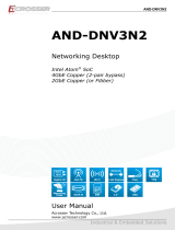
Step 3: Connect your antennas needed according to your system conguration.
The photo shows antenna from left to right are: 4G LTE, GPS, WiFi, BT.
/