Page is loading ...

AND-APL1N1FL-XX Series User Manual
User Manual
Acrosser Technology Co., Ltd.
www.acrosser.com
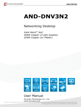
AND-APL1N1FL-XX
Intel
®
Apollo Lake series Networking Microbox
powered by SoC Celeron
®
CPU
J-Series/N-Series/E-Series
6x GbE LAN (3-pair Bypass)

AND-APL1N1FL-XX Series User Manual
2
Acrosser Technology Co., Ltd.
To read this User Manual on your smart phone, you will have to install an
APP that can read PDF le format rst. Please nd the APP you prefer from
the APP Market.
Ver: 100-001
Date: Aug. 30, 2018
Disclaimer
For the purpose of improving reliability, design and function, the information in this document
is subject to change without prior notice and does not represent a commitment on the part of
Acrosser Technology Co., Ltd.
In no event will Acrosser Technology Co., Ltd. be liable for direct, indirect, special, incidental, or
consequential damages arising out of the use or inability to use the product or documentation,
even if advised of the possibility of such damages.
Copyright
This document contains proprietary information protected by copyright. All rights are reserved.
No part of this manual may be reproduced by any mechanical, electronic, or other means in
any form without prior written permission of Acrosser Technology Co., Ltd.
Trademarks
The product names appear in this manual are for identication purpose only. The trademarks
and product names or brand names appear in this manual are the property of their respective
owners.
Purpose
This document is intended to provide the information about the features and use of the product.
Audience
The intended audiences are technical personnel, not for general audiences.

AND-APL1N1FL-XX Series User Manual
3www.acrosser.com
Table of Contents
1. System Introduction ...................................................................... 5
1.1. Specications ............................................................................................................. 5
1.2. Package Contents ...................................................................................................... 7
1.3. Dimensions ................................................................................................................. 8
1.4. Front Panel ................................................................................................................. 9
1.5. Rear Panel................................................................................................................ 10
2. Components Assembly ................................................................11
2.1. 2.5” SATA SSD Installation ........................................................................................11
2.2. DIMM Card Installation ............................................................................................. 13
2.3. Antenna Connection ................................................................................................. 14
3. BIOS Settings ............................................................................... 16
3.1. Main Setup ............................................................................................................... 16
3.2. Advanced Setup ....................................................................................................... 17
3.2.1. Trusted Computing ........................................................................................ 18
3.2.2. ACPI Settings ................................................................................................ 19
3.2.3. Super IO Conguration ................................................................................. 20
3.2.4. Hardware Monitor .......................................................................................... 21
3.2.5. Hardware Monitor .......................................................................................... 22
3.2.6. LAN Bypass Control & Watchdog Settings ................................................... 22
3.2.7. Power Button & PXE Control ........................................................................ 23
3.2.8. SATA Drivers ................................................................................................. 24
3.2.9. S5 RTC Wake Settings ................................................................................. 25
3.2.10. Serial Port Console Redirection .................................................................... 26
3.2.11. CPU Conguration ........................................................................................ 27
3.2.12. CSM Conguration ........................................................................................ 28
3.2.13. USB Conguration ........................................................................................ 29
3.3. Chipset Setup ........................................................................................................... 30
3.3.1. North Bridge .................................................................................................. 31
3.3.2. South Bridge ................................................................................................. 32
3.3.3. South Cluster Conguration .......................................................................... 33
3.4. Security Setup .......................................................................................................... 34
3.5. Boot Setup ................................................................................................................ 35
3.6. Save & Exit Setup..................................................................................................... 36
4. Driver and Utility Installation ...................................................... 37
4.1. Driver CD Interface Introduction ............................................................................... 37
4.2. Windows Installation ................................................................................................. 38
4.2.1. Driver Installation Page ................................................................................. 39

AND-APL1N1FL-XX Series User Manual
4
Acrosser Technology Co., Ltd.
4.2.2. Utility Page .................................................................................................... 41
4.2.3. Application Installation Page ......................................................................... 45
4.2.4. Document Page ............................................................................................ 48
4.3. Linux Conguration................................................................................................... 49
5. Software Installation and Programming Guide ........................ 52
5.1. Introduction ............................................................................................................... 52
5.1.1. Environment .................................................................................................. 52
5.1.2. GPIO ............................................................................................................. 52
5.1.3. Watchdog ...................................................................................................... 52
5.1.4. LAN Bypass Subsystem ................................................................................ 52
5.2. File Descriptions ....................................................................................................... 53
5.2.1. GPIO/Watchdog/LAN Bypass Subsystem..................................................... 53
5.3. API List and Descriptions ......................................................................................... 53
5.3.1. GPIO ............................................................................................................. 53
5.3.2. Watchdog ...................................................................................................... 54
5.3.3. LAN Bypass Subsystem ................................................................................ 54
5.3.4. Notes ............................................................................................................. 56
6. FAQ ............................................................................................... 57
Q 1. Where is the serial number located on my system? ................................................. 57

AND-APL1N1FL-XX Series User Manual
5www.acrosser.com
1. System Introduction
1.1. Specifications
System
Thermal Solution • 1x Fanless Heatsink
CPU • Intel
®
Apollo Lake SoC Celeron
®
J-Series CPU
• Intel
®
Apollo Lake SoC Celeron
®
N-Series CPU
• Intel
®
Apollo Lake SoC Celeron
®
E-Series CPU
System Memory • 1x SO-DIMM DDR3L-1866 (up to 8GB)
BIOS • Support Console Re-direction
• Support Bypass Setting
Status Normal Bypass
SYS (ON) V
SYS (OFF) V
WDT (Timeout) V
PWR (Lost) Remained prior status
• Support Boot from RJ45 LAN[1:6]
BIOS Function • Support SSID
Network Interface
Ethernet Chip • 6x GbE Copper
• Intel
®
I210-AT (10/100/1000Mbps) LAN[1:6]
LAN Bypass
(3-pair)
• (1st LAN bypass) by LAN[1:2]
• (2nd LAN bypass) by LAN[3:4]
• (3rd LAN bypass) by LAN[5:6]
Storage
SATA/mSATA • 1x 2.5” Internal HDD Bay (default),
or 1x mSATA Socket (full-size module) (reserved)
CF/CFast • 1x CF Socket (default),
or 1x CFast Socket (reserved)
Other Features
WatchDog Timer • Software Programmable 0 ~ 255 seconds
(0=Disable Timer)
Battery • Lithium Battery, 3V 220mAH (CR2032)

AND-APL1N1FL-XX Series User Manual
6
Acrosser Technology Co., Ltd.
Hardware Monitoring • CPU Voltage
• CPU Temperature
• System Temperature
• RTC Battery Voltage
Security • TPM 2.0
Power Requirement
Power Adapter • DC-IN 12V / 60W Adapter (AT mode)
Software
OS Support • Windows 10 IoT Enterprise LTSB Entry, (64-bit)
• Linux Kernel 4.4 & above, (64-bit)
Mechanical & Environment
Dimension • 280mm (W) x 209mm(D) x 44mm(H)
Operating Temperature • 0 ~ 40°C (32 ~ 104°F)
Storage Temperature • -20 ~ 80°C (-4 ~ 176°F)
Relative Humidity • 0 ~ 90% @40°C, non-condensing
EMC & Safety
EMC • CE, FCC Class A
Vibration Test • IEC 60068-2-64, 5~500Hz, 3GRMS
Drop Test • ISTA-2A 2006


AND-APL1N1FL-XX Series User Manual
8
Acrosser Technology Co., Ltd.
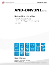
1.3. Dimensions
(Unit: mm)
DC12V
Bypass
USB3.0
PWR RST
Console
Bypass3 Bypass2 Bypass1
ANT1 ANT3 ANT2
LAN6 LAN5 LAN4 LAN3 LAN2 LAN1
209
218
9
280
44
48.4

AND-APL1N1FL-XX Series User Manual
9www.acrosser.com
1.4. Front Panel
Link Blinking
• USB
USB 3.0 connector.
• PWR
Power Indicator.
• HDD
HDD Indicator. PWR: Green, HDD: Yellow.
• BYP 1, BYP 2, BYP 3
Bypass LED. ln-active: Green, Active: Red.
• LAN1 ~ LAN6
LAN LED.
Link Blinking
LED Light Status
Upper Green Blinking Link w/ Act
Middle Green On 1000Mbps
Lower Yellow 100Mbps
Lower Off 10Mbps

AND-APL1N1FL-XX Series User Manual
10
Acrosser Technology Co., Ltd.
1.5. Rear Panel
DC12V
Bypass
USB3.0
PWR RST
Console
Bypass3 Bypass2 Bypass1
ANT1 ANT3 ANT2
LAN6 LAN5 LAN4 LAN3
LAN2 LAN1
• DC12V
DC12V power input jack.
• Bypass
Bypass LED. ln-active: Green, Active: Red.
• PWR
Power button.
• RST
Reset button.
• Console
COM1 connector.
• USB3.0
USB3.0 connectors.
• LAN1 ~ LAN6
LAN connectors.
LED Light Status
LED1
Green Blinking Link w/ Act
Green On Link w/o Act
Off No Link
LED2
Off 10Mbps
Orange On 100Mbps
Green On 1000Mbps
• ANT1 ~ ANT3
Antenna Hole


AND-APL1N1FL-XX Series User Manual
12
Acrosser Technology Co., Ltd.
Step 3: Connect the SATA cable.
Step 4: Lock the cover plate with screws.


AND-APL1N1FL-XX Series User Manual
14
Acrosser Technology Co., Ltd.
2.3. Antenna Connection
After having installed your wireless module into the mainboard and the antenna
socket, you may connect your antennas needed according to your system
conguration.
Step 1: Make sure your antenna type matches with the antenna socket.
Step 2: Insert the antenna plug into the antenna socket.


AND-APL1N1FL-XX Series User Manual
16
Acrosser Technology Co., Ltd.
3. BIOS Settings
This chapter describes the BIOS menu displays and explains how to perform
common tasks needed to get the system up and running. It also gives detailed
explanation of the elements found in each of the BIOS menus. The following topics
are covered:
• Main Setup
• Advanced Setup
• Chipset Setup
• Security Setup
• Boot Setup
• Save & Exit Setup
Once you enter the Award BIOS™ CMOS Setup Utility, the Main Menu will appear
on the screen. Use the arrow keys to highlight the item and then use the <Pg Up>
<Pg Dn> keys to select the value you want in each item.
3.1. Main Setup
The BIOS setup main menu includes some options. Use the [Up/Down] arrow key to
highlight the option, and then press the <Enter> key to select the item and congure
the functions.
Aptio Setup Utility - Copyright (C) 2018 American Megatrends, Inc.
Version 2.18.1263. Copyright (C) 2018 American Megatrends, Inc.
→←: Select Screen
↑↓: Select Item
Enter: Select
+/-: Change Opt.
F1: General Help
F2: Previous Values
F3: Optimized Defaults
F4: Save & Exit
ESC: Exit
Main Advanced Chipset Security Boot Save & Exit
Set the Date. Use Tab to
switch between Date
elements.
Default Ranges:
Year: 2005-2099
Months: 1-12
Days: dependent on month
BIOS Information
BIOS Version
Build Date and Time
Ststem Date
Ststem Time
Access Level
APL1N1FL 010-004
05/04/2018 11:22:33
[Wed 06/13/2018]
[11:22:33]
Administrator
Note: Listed at the bottom of the menu are the control keys. If you need any help with the
item elds, you can press <F1> key, and it will display the relevant information.

AND-APL1N1FL-XX Series User Manual
17www.acrosser.com
• System Date
Set the system date. Use Tab to switch between Date elements.
• System Time
Set the system time. Use Tab to switch between Time elements.
3.2. Advanced Setup
Aptio Setup Utility - Copyright (C) 2018 American Megatrends, Inc.
Version 2.18.1268. Copyright (C) 2017 American Megatrends, Inc.
→←: Select Screen
↑↓: Select Item
Enter: Select
+/-: Change Opt.
F1: General Help
F2: Previous Values
F3: Optimized Defaults
F4: Save & Exit
ESC: Exit
Main
Advanced Chipset Security Boot Save & Exit
Trusted Computing
ACPI Settings
Super IO Configuration
Hardware Monitor
Fan Function
LAN Bypass Control & Watchdog Settings
Power Button & PXE Control
SATA Drivers
S5 RTC Wake Settings
Serial Port Console Redirection
CPU
Configuration
CSM Configuration
USB Configuration
Trusted Computing
Settings.
• Trusted Computing
Trusted Computing Settings.
• ACPI Settings
Set system ACPI parameters.
• Super IO Conguration
System Super IO Chip Parameters.
• Hardware Monitor
Monitor hardware status.
• Fan Function
Fan function setting.
• LAN Bypass Control & Watchdog Settings
LAN Bypass Control & Watchdog Settings
• Power Button & PXE Control
Power Button & PXE Control
• SATA Drivers
Select the SATA device conguration setup options.

AND-APL1N1FL-XX Series User Manual
18
Acrosser Technology Co., Ltd.
• S5 RTC Wake Settings
Enable system to wake from S5 using RTC alarm.
• Serial Port Console Redirection
Set serial port console redirection.
• CPU Conguration
CPU Conguration Parameters.
• CSM Conguration
Compatibility Support Module Conguration. Enable/Disable Option ROM execution
settings, etc.
• USB Conguration
USB Conguration Parameters.
3.2.1. Trusted Computing
Set trusted computing settings
Aptio Setup Utility - Copyright (C) 2018 American Megatrends, Inc.
Version 2.18.1263. Copyright (C) 2018 American Megatrends, Inc.
→←: Select Screen
↑↓: Select Item
Enter: Select
+/-: Change Opt.
F1: General Help
F2: Previous Values
F3: Optimized Defaults
F4: Save & Exit
ESC: Exit
Advanced
TPM20 Device Found
Security Device Support
Active PCR banks
Available PCR banks
SHA-1 PCR Bank
SHA256 PCR Bank
Pending Operation
Platform Hierarchy
Storage Hierarchy
Endorsement Hierarchy
TPM2.0 UEFI Spec Version
Physical Presence Spec Version
TPM 20 InterfaceType
Device Select
[Enabled]
SHA-1
SHA-1,SHA256
[Enabled]
[Disabled]
[None]
[Enabled]
[Enabled]
[Enabled]
[TCG_2]
[1.2]
[TIS]
[Auto]
Enables or Disables BIOS
support for security
device. O.S. will not
show Security Device.
TCG EFI protocol and
INT1A interface will not
be available.
• Security Device Support
Enables or Disables BIOS support for security device. O.S. will not show Security
Device. TCG EFI protocol and INT1A interface will not be available.
• SHA-1 PCR Bank
Enables or Disables SHA-1 PCR Bank.
• SHA256 PCR Bank
Enables or Disables SHA256 PCR Bank.

AND-APL1N1FL-XX Series User Manual
19www.acrosser.com
• Pending Operation
Schedule an Operation for the Security Device. NOTE: Your Computer will reboot
during restart in order to change State of Security Device.
• Platform Hierarchy
Enables or Disables Pateform Hierarchy.
• Storage Hierarchy
Enables or Disables Storage Hierarchy.
• Endorsement Hierarchy
Enables or Disables Endorsement Hierarchy.
• TPM2.0 UEFI Spec Version
Select the TCG2 Spec Version Support,
TCG_1_2: The Compatible mode for Win8/Win10
.
TCG_2: Support new TCG2 protocol and event format for Win10 or later
.
• Physical Presence Spec Version
Select to Tell O.S. to
support PPI Spec Version 1.2
or 1.3. Note some HCK tests
might not support 1.3.
• Device Select
TPM 1.2 will restrict support to TPM 1.2 devices.
TPM2.0 will restrict support to
TPM 2.0 devices, Auto will support both with the default set to TPM2.0 devices if not
found, TPM1.2 devices will be enumerated
3.2.2. ACPI Settings
Set system ACPI parameters.
Aptio Setup Utility - Copyright (C) 2018 American Megatrends, Inc.
Version 2.18.1263. Copyright (C) 2018 American Megatrends, Inc.
→←: Select Screen
↑↓: Select Item
Enter: Select
+/-: Change Opt.
F1: General Help
F2: Previous Values
F3: Optimized Defaults
F4: Save & Exit
ESC: Exit
Advanced
ACPI Settings
Enable ACPI Auto Configuration
[Disabled]
Enables or Disables
BIOS ACPI Auto
Configuration.

AND-APL1N1FL-XX Series User Manual
20
Acrosser Technology Co., Ltd.
• Enable ACPI Auto Conguration
Enables or Disables BIOS ACPI Auto Conguration.
3.2.3. Super IO Configuration
Set system super IO chip parameters.
Aptio Setup Utility - Copyright (C) 2018 American Megatrends, Inc.
Version 2.18.1263. Copyright (C) 2018 American Megatrends, Inc.
→←: Select Screen
↑↓: Select Item
Enter: Select
+/-: Change Opt.
F1: General Help
F2: Previous Values
F3: Optimized Defaults
F4: Save & Exit
ESC: Exit
Advanced
Super IO Configuration
Super IO Chip
COM1
COM2
Set Parameters of
Serial Port 1
• COM1
Set Parameters of Serial Port 1.
• COM2
Set Parameters of Serial Port 2.
/