Page is loading ...

© 2017 Emerson. All Rights Reserved.Emerson.com/FinalControl
Before installation these instructions must be fully read and understood
YARWAY MODEL 950 HANCOCK FORGED STEEL GATE VALVE
InstallatIon and maIntenance InstructIons
VCIOM-03223-EN 18/02
1 SAFETY NOTICE
Proper installation, operation and maintenance
is essential to the safe and reliable operation
of all valve products. The relevant procedures
described in this manual, are effective methods
of performing the required tasks. Some of
these procedures require the use of tools
specifically designed for an intended purpose.
These special tools should be used when, and
as, recommended.
It is important to note that this manual contains
various “safety messages” which should be
carefully read in order to minimize the risk of
personal injury, or the possibility that improper
procedures will be followed which may damage
the product, or render it unsafe. It is also
important that these “safety messages” are
not exhaustive.
PRODUCT SAFETY SIGN AND LABEL SYSTEM
If and when required, appropriate safety labels
have been included in the rectangular margin
blocks throughout this manual. Safety labels
are vertically oriented rectangles as shown in
the representative examples (below), consisting
of three panels encircled by a narrow border.
The panels can contain four messages which
communicate:
• The level of hazard seriousness
• The nature of the hazard
• The consequence of human, or product,
interaction with the hazard.
• The instructions, if necessary, on how to
avoid the hazard.
The top panel of the format contains a signal
word (DANGER, WARNING, CAUTION or
ATTENTION) which communicates the level of
hazard seriousness.
The center panel contains a pictorial which
communicates the nature of the hazard, and
the possible consequence of human or product
interaction with the hazard. In some instances
of human hazards the pictorial may, instead,
depict what preventive measures to take, such
as wearing protective equipment.
The bottom panel may contain an instruction
message on how to avoid the hazard, this
message may also contain a more precise
definition of the hazard, and the consequences
of human interaction with the hazard, than can
be communicated solely by the pictorial.
DANGER
Do not remove bolts if pressure in line, as this will
result in severe personal injury or death.
WARNING
Know all valve exhaust/leakage points to avoid
possible severe personal injury or death.
CAUTION
Wear necessary protective equipment to preven
possible injury.
ATTENTION
Do not drop or strike valve.
Emerson can not possibly know, evaluate, and
advise any customer of all the conceivable ways
in which tasks might be performed, or of the
possible hazardous consequences of each way.
Consequently, Emerson has not undertaken
any such broad evaluation and, thus, anyone
who uses a procedure and/or tool, which is
not recommended by Emerson, or deviates
from Emerson recommendations, must be
thoroughly satisfied that neither personal
safety, nor valve safety, will be jeopardized
by the method and/or tools selected. If not
so satisfied, contact Emerson representative
if there are any questions relative to tools/
methods. Some of the products manufactured
by Emerson may be used in radioactive
environments. Consequently, prior to starting
any operation in a radioactive environment, the
proper “health physics” procedures should be
consulted and followed, if applicable.
The installation, operation and maintenance
of valves and/or valve products may involve
proximity to fluids at extremely high pressure
and/or temperature. Consequently, every
precaution should be taken to prevent injury
to personnel during the performance of any
procedure. These precautions should consist
of, but are not limited to, ear drum protection,
eye protection, and the use of protective
clothing, (i.e., gloves, etc.) when personnel
are in or around a valve work area. Due to
the various circumstances and conditions in
which these operations may be performed
and the possible hazardous consequences of
each way, Emerson can not possibly evaluate
all conditions that might injure personnel or
equipment. Nevertheless, Emerson does offer
the safety precautions for customer information
only.
It is the responsibility of the purchaser or user
of Emerson valves/equipment to adequately
train all personnel who will be working with
the involved valves/equipment. Further, prior
to working with the involved valves/equipment,
personnel who are to perform such work
should become thoroughly familiar with the
contents of this manual.

2
1
3
2
4
5
6
7
8
9
10
13
11
12
14
15
16
17
18
19
20
21
YARWAY MODEL 950 HANCOCK FORGED STEEL GATE VALVE
InstallatIon and maIntenance InstructIons
2 SAFETY PRECAUTIONS
• Class 800 valves are shipped with the packing
gland nuts only hand tight. Always tighten
the packing gland nuts before pressurizing
a valve.
• Do not attempt to remove the packing gland
nuts while the valve is under pressure.
• Do not attempt to eliminate bonnet gasket
leakage by tightening the bonnet bolts while
the valve is under pressure.
• The bonnet should not be removed while the
valve is under pressure.
• Do not attempt to remove the thread bushing
while the valve is under pressure.
• All valves equipped with the permanent (fixed)
backseats are capable of being repacked
under pressure. However, due to the inherent
dangers* involved in working on equipment
under internal pressure, it is strongly
recommended that backseats only be used to
prevent this line fluid from escaping through
the stuffing box, until such time as all internal
pressure and/or hazardous fluids can be
removed,and the valve can be repacked under
safe conditions.
• No alteration and/or modification should be
made to any valve, except as sanctioned and/
or authorized by Emerson.
• Any modification of a valve, to accept a gear
operator, motor operator or pneumatic /
hydraulic actuator should be accomplished
using only those designs sanctioned and/or
authorized by Emerson.
• Never install, or attempt to use, any valve that
is not properly identified as to its material and
pressure class.
* The valve may have been modified internally by
other than Emerson personnel, and/or may have
damaged internal parts (e.g., broken, cracked
or severely damaged stem). Such unauthorized
modification, or such possible damage, could cause
a sudden rupture, or pressurization, of the packing
while the packing is being removed or installed, thus
endangering the surrounding equipment and safety
of personnel.
3 INTRODUCTION TO CLASS 800 VALVES
All valves are made to the highest quality
standards and meet or exceed the specification,
code and application requirements for which
they are designed. Although Emerson valves
are among the most ruggedly designed
products in the industry, they are still precision
pieces of equipment and, as such, require
proper care. Adherence to the handling,
storage, installation and maintenance
procedures contained in this manual will
greatly enhance the service life of the valve,
as well as help ensure the safety of personnel.
It is essential that all personnel assigned to
install, operate and/or service valves be trained,
have read and be thoroughly familiar with all
the information contained in this manual, prior
to starting work on the product. In the event
that there are any questions relative to the
instructions contained in this manual, contact
our service center for clarification prior to
proceeding.
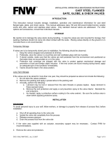
4 DESIGN FEATURES AND NOMENCLATURE
The principal design features and parts
nomenclature for the Type 950-4 valves are
provided in Figure 1.
Part
No. Nomenclature
Spare part
classification
1 Thread bushing nut Class 5
2 Marker plate N/A
3 Handwheel Class 3
4 Key Class 3
5 Handwheel washer Class 5
6 Thread bushing washer Class 5
7 Thread bushing Class 2
8 Packing gland nut Class 2
9 Packing glandflange Class 2
10 Packing gland Class 2
11 Stem* Class 1
12 Packing glandbolt Class 2
13 Pin Class 2
14 Packing cartridge Class 1
15 Bonnet bolt Class 3
16 Bonnet Class 5
17 Gasket Class 1
18 Body Class 5
19 Seat facing N/A
20 Wedge* Class 1
21 Seat Class 3
22 Stake lock N/A
FIGURE 1
Type 950-4 and gate valves
* New to stem and wedge design changes, wedge
and stem must be replaced as a unit.

3
¼ - 4 225
⅜ - 4 225
½ - 4 225
¾ - 4 225
1 4 6 300
1¼ 5 6 400
1½ 5 6 400
2 6 7 500
- 7 8 550
YARWAY MODEL 950 HANCOCK FORGED STEEL GATE VALVE
InstallatIon and maIntenance InstructIons
6 OPERATION
When opening or closing the valve, torques, as
specified in Table 1, should not be exceeded.
If the valve is not tight when properly torqued,
opening the valve and reclosing may free
foreign material trapped on the seats. Do not
use a wrench to close the valve. If the valve will
not shut off tightly, when seating surfaces are
free of foreign material, the valve should be
scheduled for servicing.
7 HANDLING
Care should be exercised when handling all
valves, in order to prevent damage to the
handwheel or stem. Valves should not be
dropped or subjected to sharp impact during
transportation or installation.
ATTENTION
Do not drop or strike valve.
8 STORAGE
Indoor storage of valves is recommended. If
prolonged storage is anticipated, the valves
should be stored in a humidity controlled
storage area. If valves are ordered to a more
stringent cleaning and storage procedure, the
recommendations in that procedure should be
followed.
9 PRE-INSTALLATION
Prior to installation, the following steps should
be taken:
1. Leave end caps in place until ready for
installation, then remove.
2. Inspect both ports for obstruction or foreign
materials. Clean when necessary.
3. Valves are shipped with gland nuts loose.
These nuts must be tightened before putting
the valve in service.
4. If packing is not installed in the valve, refer
to the maintenance instructions (see section
15.D) in this manual for packing installation
directions.
ATTENTION
Tighten gland nuts before placing valve in service.
TABLE 1 - MAXIMUM PERMISSIBLE TORQUE
Valve size
950
Handwheel Dia. - inches Inch-pounds
At least Less than (+ - 0%)
5 OPERATING PRINCIPLES
Type 950-4 valves are basic gate valves with
non-rotating stems. These valves are easily
operated by rotating the handwheel clockwise
to close and counterclockwise to open. Gate
valves are not designed for throttling service.
For long service life with minimum of erosion
of body, seats, and wedge, the valves should be
operated in a full open or closed position. Gate
valves have an integral backseat and when the
valve is operated in the full open position, the
valves should be
1
/
2 turn off the backseat.
WARNING
Know nuclear "health physics" procedures, if
applicable, to avoid possible severe personal
injury or death.
CAUTION
Wear necessary protective equipment to preven
possible injury
DANGER
Do not remove packing gland nuts, bonnet or
thread bushing if valve is under pressure, as this
will result in severe personal injury or death.
ATTENTION
Do not alter or modify valve without authorization.
ATTENTION
Do not install or use valve if material and/or
pressure class are not known.
When possible, type 950 gate valves should be
operated fully open, but ½ turn off the backseat.
When a valve is in a partially closed position,
velocity of flow is increased and the possibility
of erosion of the seating surfaces is greater.
ATTENTION
Do not exceed specified torques, or use a wrench
to close valve.

4
¼ - ¾ 7220815 7221115
1 7220816 7221116
1¼ -1½ 7220817 7221117
2 7220818 7221118
2½ - 3 7220823 7221123
YARWAY MODEL 950 HANCOCK FORGED STEEL GATE VALVE
InstallatIon and maIntenance InstructIons
B. Specific steps
To repack a valve under pressure, when
absolutely dictated by necessity, turn
the handwheel counterclockwise until
the stem makes up on the backseat. If
the original leak has stopped, loosen the
packing gland nuts, but do not remove.
The reason for not removing the gland nuts is
to allow a reasonable amount of time to pass in
order to be certain that the backseat is holding
tight and there is no evidence of leakage or
packing movement. Once assured that the
backseat is holding tight, proceed to remove
the packing gland nuts completely. Wire the
packing gland and packing gland flange to
the handwheel to allow more room to remove
the packing. When removing the old packing,
care should be taken not to damage the stem
or packing chamber wall. When valves are
repacked without disassembly, the packing
illustrated in Figure 2, part numbers for which
are shown in Table 2, must be used.
When inserting new packing rings and bull
rings, stagger the splits in the successive rings
at 90 degree angles. (Again, see Figure 2.)
TABLE 2 - PACKING
Valve size
NPS 950
Packing cart
part no.
Packing set
part no*
Top bull ring
Lower bull ring
Individual split
grafoil rings
FIGURE 2
Packing set individual split rings
* Packing set is supplied in a set of individual split
rings with bull rings.
12 PACKING LEAKAGE
For parts nomenclature, refer to Figure 1
of this manual. When the valve has been
placed in service and has been brought up to
temperature, the packing should be checked
for leakage. Close the valve ½ turn and check
the packing for leakage. If leakage occurs,
adjust the packing gland. To adjust the packing
gland, run the nuts down evenly ½ turn on all
gland bolts and check for leakage. If leakage
continues, turn the nuts down another ½ turn
on all bolts. Turn the handwheel back and forth
½ turn after each adjustment. Again, check for
leakage. If binding of the stem occurs and the
leakage has stopped, loosen the packing nuts
¼ turn. Check the stem for binding and check
for leakage. The object is to tighten the packing
a minimum amount to prevent leakage, while
producing a minimum amount of stem binding.
If leaking through the packing continues and
cannot be completely stopped by tightening
the packing, then the valve should be firmly
backseated to prevent steam damaging the
stem or the bonnet. The valve should then be
scheduled for inspection and repair at shut
down.
13 REPACKING UNDER PRESSURE
A. General information
The bolted bonnet valve design is fitted with
an integral backseat as standard. Although
the backseat provides a means of packing the
gland box under pressure Emerson does not
recognize this as a safe practice. (Again, see
“Safety precautions” Section 2).
DANGER
Do not repack a valve under pressure unless it is
absolutely necessary, as this will result in severe
personal injury or death.
10 INSTALLATION
Type 950-4 Gate valves may be installed with
the stem in any desired position and they
will operate equally well with flow in either
direction.
ATTENTION
Do not ground to bonnet, stem or handwheel
when welding.
11 WELDING
Valves should be opened and backseated prior
to welding. Care should be taken not to ground
to the valve bonnet, stem, or handwheel.
Maintain 359° interpass temperature
requirement when installing stainless
steel valves.
Next, reinstall the packing gland and gland
flange onto the bolts and tighten the nuts
evenly by alternately turning each nut one full
turn. When the nuts are tightened securely,
slowly open the valve slightly and check for
packing leakage. If the packing leaks, tighten
the nuts alternately ½ turn each and check
again. When the leakage stops, operate the
valve open and closed about ½ turn to check
if the stem is binding with the packing.
Should any binding be severe, yet the
packing is not leaking, loosen the gland nuts
approximately ¼ turn each to relieve the stem
binding, checking again for leakage through
the packing.
The valve can now be adjusted to the proper
position to attain the desired flow rate.

5
YARWAY MODEL 950 HANCOCK FORGED STEEL GATE VALVE
InstallatIon and maIntenance InstructIons
C. Disassembling the bonnet assembly
The bonnet assembly may now be
disassembled. Remove the two packing gland
nuts. Free the packing gland from the packing
chamber.
Remove the stem by rotating the handwheel
clockwise while holding the stem until it
disengages the thread bushing. The stem may
now be forced through the packing chamber.
Remove the packing gland flange and the
packing gland.
Remove the thread bushing nut. Remove
the handwheel, washer and key. The thread
bushing and thread bushing washer can now be
removed. Remove the packing, taking care not
to damage the stuffing box.
15 MAINTENANCE
A. General information
1. The use of a wrench on the handwheel is
not recommended. If the valve will not shut
off tightly when seating surfaces are free
of foreign material, refinishing of seat and
wedge is indicated.
2. Continued leakage through the stem
packing may damage the valve beyond
repair. The packing gland should be
adjusted as soon as leakage is detected
(See section 12).
B. Removing and replacing seat rings
1. General information
Emerson gate valves have renewable seat
rings expanded into the valve body. Should it be
desirable to replace the seat rings remove the
valve from the line and follow the procedure
specified below.
2. Removing the seat rings
Seat rings may be removed with a hardened
steel punch, in a press. (See Figure 3 and
Table 3.) As an alternative, with a heavy
hammer, and with care, they may be removed
with a blunt chisel. The seat ring should be
driven out of socket and then removed through
the bonnet opening in the valve.
3. Installing new seat rings
Seat rings may be installed by the drift method
of expanding the ring. In this process a tool
called a drift is used. (See Figure 4 and Table 4.)
Before placing the seat rings in the valve body,
be sure that the surfaces of the body and the
seat rings are clean and all free of all burrs,
scales and foreign matter. Place the seats
in the body with the narrow section up. They
should have just sufficient clearance to turn
freely in the body.
14 DISASSEMBLY
A. General information
Type 950-4 Gate valves can easily be
disassembled for inspection, maintenance
or repair if the following procedures are
adhered to.
B. Removing the bonnet assembly
Note: do not remove the bonnet bolts if the valve
is under line pressure.
Before beginning disassembly, open the valve
until light contact on the backseat is felt. This
will ensure that the wedge does not become
free of the stem. (refer to Figure 1 for parts
nomenclature.)
Remove the four bonnet bolts using standard
socket wrenches. The bonnet assembly may
then be lifted off.
Remove the bonnet gasket from the body,
taking care not to damage the gasket seating
surface. The wedge may now be removed from
the stem, after turning the handwheel several
times as if closing the valve.
DANGER
Do not remove bonnet bolts if pressure in line, as
this will result in severe personal injury or death.
3. The packing gland flange should be adjusted
an equal amount on each side to ensure
proper compression of the packing and to
avoid contact of the gland or flange with the
stem. If adjustment of the packing gland
does not eliminate leakage, additional
packing should be inserted, or the valve
should be completely repacked with
packing suited to the service.
New packing may shrink when first put in
service and additional packing may be required.
Packing glands on valves used on elevated
temperatures should be adjusted shortly after
being brought up to operating temperature.
ATTENTION
Do not exceed specified torques, or use a wrench
to close valve.
Insert the wedge and stem, and line up the seat
rings with the wedge by using a rocking motion
of the stem/wedge assembly. If necessary, the
seats may be rotated to insure a good fit with
the wedge. When proper alignment is obtained,
the corners of the wedge and the machined
guides will show a uniform clearance on all
four corners.
Tap the end of the stem lightly to seat the
wedge. The wedge seat joint may be further
checked by inserting a light in the bonnet
opening and checking through the port opening.
The valve is now ready for final assembly. Do
not remove seat rings after they have been
properly positioned. Assemble the valve,
complete with packing, then close the valve,
forcing the wedge into a closed position. The
valve is now ready for expanding the seat skirt.
The seat rings are expanded with a drift, a well
lubricated, tapered expanding tool, in a press,
or by a roller type expanding tool in a drill press
or lathe. The drift should be driven in until the
seat is fully expanded and tight against the
body. Reverse the valve and expand the second
seat ring, being careful not to over-expand.
Loosen the wedge to check the work, and if the
seats have been properly expanded, the valve is
ready for test.

6
ØE
G
45°
F
C
ØB ØA
ØE
45°
C
B
F
R
R
ØA
20°
1
/
16
3
/
32
¼ .420 .366 3 ½ 1
5
/
8
.418 .362
⅜ .420 .366 3 ½ 1
5
/
8
.418 .362
½ .495 .454 3
3
/
8
5
/
8 1
7
/
8
.493 .450
¾ .620 .495 3½ ¾ 2
.618 .491
1 .930 .727 3
7
/
8 1 2
1
/
8
.928 .723
- 1.085 .727 4 1 2
1
/
8
1.080 .723
1 -1¼ 1.310 .547 3
5
/
8 1
3
/
8 1
9
/
16
1.308 .537
1 -1½ 1.310 .547 3
5
/
8 1
3
/
8 1
9
/
16
1.308 .537
2 1.684 .844 7½ 1
3
/
4 5½
1.690 .834
- 2.312 .844 7½ 2
1
/
2 5½
2.305 .834
¼ - ¾ 7194001 7220815 7221115
1 7194002 7220816 7221116
1¼ -1½ 7194003 7220817 7221117
2 7194004 7220818 7221118
2½ - 3 7194007 7220823 7221123
¼ .431 .302
9
/
16
9
/
16 2
7
/
16 8
.429 .300
⅜ .495 .365
9
/
16
5
/
8 2
7
/
16 8
.493 .362
½ .495 .365
9
/
16
5
/
8 2
7
/
16 8
.493 .363
¾ .620 .490
5
/
8 ¾ 2
1
/
2 8
1
/
8
.618 .488
1 .932 .740
7
/
8 1
1
/
16 2
3
/
4 8
1
/
8
.930 .738
- 1.085 .930
7
/
8 1
1
/
16 2
3
/
4 8
1
/
8
1.080 .925
1 -1¼ 1.307 1.115
13
/
16 1
5
/
16 2
1
/
2 8¼
1.305 1.113
1 -1½ 1.307 1.115
13
/
16 1
5
/
16 2
1
/
2 8¼
1.305 1.113
2 1.557 1.365
7
/
8 1
9
/
16 3 8¼
1.555 1.363
- 2.300 1.900
7
/
8 2
1
/
2 4 9
2.295 1.895
TABLE 3 - PUNCH DIMENSIONS
Valve size
NPS 950 A B C E F
1
/
16 x 45°
Chamfer
1
/
8 x 45°
Chamfer
1
/
16 x 45°
Chamfer
FIGURE 3
Seat removal punch
FIGURE 4
Drift tool
D. Repacking with no pressure
Disassembled valves may be repacked with
a packing set composed of two bull rings and
individual rings of compressed graphite, or with
a packing cartridge of compressed graphite
filament with bull rings, as shown in Figure 5.
Appropriate part numbers for both packing sets
and packing cartridges are shown in Table 5.
Valves of the bolted bonnet design may be
successfully repacked with any good grade of
packing as recommended for the appropriate
service.
Recommended factory replacement packings
are shown in Table 5. Unless otherwise
specified, valves of the bolted bonnet design
are packed by Emerson with a solid graphite
packing cartridge, consisting of compressed
graphite ribbon with split bull rings of braided
graphite. Split ring graphite packing is also
available as service packing.
TABLE 4 - DRIFT TOOL DIMENSIONS
Valve size
NPS 950 A B C E F G
Individual split
graphite intermediate
Solid graphite
intermediate cartridge
Upper bull
ring
TABLE 5 - PACKING AND GASKET PART
NUMBERS
Valve size
NPS 950
Bonnet
gasket part
no.
Packing
cartridge
part no.
Packing
set part
no.
Upper bull
ring
lower bull
ring
lower bull
ring
FIGURE 5
YARWAY MODEL 950 HANCOCK FORGED STEEL GATE VALVE
InstallatIon and maIntenance InstructIons
E. Bonnet gasket replacement
All Hancock Class 800 valves use a propriatary
spiral wound gasket located between the
specifically designed body flange and bonnet
flange to provide the tightest possible joint.
Gasket compression is an important factor in
obtaining a tight joint. The dimensions of these
parts are shown in Figure 6. Replacement
gaskets may be obtained from Emerson.
See Table 5 for part numbers.
NOTES
When a valve has been disassembled for any reason,
the gasket must be replaced to assure reliable
performance of the bonnet joint.
A clean dry surface is necessary for a tight seal.

7
0.187
+
-
0.000
0.005
0.087
+
-
0.000
0.005
0.092
+
-
0.006
0.000
0.125 0.005
+
-
3
1 4
2
¼ , ½ ½ - 13 65
1
9
/
16 - 12 100
1¼ ,1½
5
/
8 - 11 135
2
5
/
8 - 11 135
2½ , 3
7
/
8 - 9 340
See
note
Bonnet
Body
Gasket
NPS 1 valves and smaller
NPS 1 ¼ valves and larger
125 RMS
125 RMS
FIGURE 6
Body-bonnet gasket seating dimensions
FIGURE 7
Torquing sequence
YARWAY MODEL 950 HANCOCK FORGED STEEL GATE VALVE
InstallatIon and maIntenance InstructIons
16 RE-ASSEMBLY
A. General information
Type 950-4 Gate valves are no more difficult to
reassemble than they are to disassemble.
B. Specific steps
1. Insert the correct number of packing rings
or a packing set into the gland box. Slip
the thread bushing washer over the thread
bushing, then lubricate the I.D. and O.D.
threads of the thread bushing. Insert this
assembly between the yoke arms and into
the top of the bonnet opening.
2. While holding the thread bushing up in
place, slip the handwheel washer over
the thread bushing and insert the key into
the milled slot. Assemble the handwheel
to the thread bushing. Replace marker
plate and tighten the thread bushing nut.
Upset (stake) the nut thread for locking.
Slip the packing gland and packing gland
flange through the yoke arms and align
with the packing chamber. Insert the stem
through the bottom of the yoke. Work
the stem through the packing by rotating
counterclockwise while exerting pressure.
Continue to work until the ACME threads on
the stem engage the ACME threads on the
thread bushing.
3. Slip the stem into the “T” slot of the wedge.
After the ACME threads have engaged,
rotate the handwheel counterclockwise until
the stem makes upon the bonnet backseat.
Apply lubricant to the packing gland bolt
threads. Lift the gland flange and place the
gland flange swing bolts through the flange
holes. Screw the packing gland nuts onto
the packing gland bolts.
4. The bonnet assembly is now ready for
attachment to the body. Install a new gasket
into the body recess, align the wedge to fit
between the seats then install the bonnet
assembly on the body. Lubricate the threads
of the four bonnet bolts and screw the
bolts into the body. Tighten the bolts in the
sequence shown in Figure 7. Use several
increments to obtain the maximum torque
specified in Table 6.
5. If it is necessary to replace seat rings,
proceed in accordance with section 15B.
6. This completes reassembly of the Type
950-4 Gate valve. The valve is now ready
for test.
TABLE 6 - TORQUE TABLE
Valve size
NPS 950
Torque
Ft.Lbs
{+ - 0%}
Problem
Probable cause
Corrective action
Seat leakage Foreign material between seats
and disc.
Open valve to flush material out. (See operation,
section 6.)
Steam cut or damaged wedge Replace wedge (See maintenance, section 15.B)
Valve not fully torqued closed. Add torque (See table 3, section 15)
Packing
leakage
Packing gland loose. Tighten gland bolts (See packing leakage, section 12)
Insufficient packing in box. Add packing (See repacking under pressure, section 13)
Wrong packing for the service
and conditions.
Change packing (See repacking Under pressure,
section 13)
Stem and/or bonnet steam cut. Replace stem and/or bonnet
Body-bonnet
joint leakage
Bonnet bolts loose. Tighten bonnet bolts (See re-assembly, section 16)
Thermal or hydraulic shock. Replace bonnet gasket (See bonnet gasket
replacement, section 15.E)
Corrosion of sealing surface Replace body or bonnet, as required
Steam cut sealing surface Replace body or bonnet, as required
Overpressure Replace bonnet gasket
High operating
torque
Packing gland pulled down too tight Loosen gland nuts (See packing leakage, section 12)
Stem threads not lubricated Lubricate threads (See re-assembly, section 16)
Stem or stem threads bent Replace stem
17 CLASS 800 VALVE TROUBLE SHOOTING

8
1-1/2"
SA105
CR-13
YARWAY HANCOCK
®
SIZE:
CLASS:
BODY:
FIG. NO:
800 B16.34LTD 2000 CWP
STEM: DISC:HF SEAT:HF
MADE IN TAIWAN
950
YARWAY MODEL 950 HANCOCK FORGED STEEL GATE VALVE
InstallatIon and maIntenance InstructIons
FIGURE 8
Valve marker plate
19 IDENTIFICATION AND ORDERING
ESSENTIALS
When ordering service parts, please furnish the
following information to ensure receiving the
correct replacement parts:
Identify valve by marker plate information
(see Figure 8):
1. Nominal valve size
2. Complete figure number -including dash
numbers
3. Pressure class
4. Valve type
Example:
NPS 1-½
950W-4
CL. 800
Gate valve
Specify parts required by:
1. Part name
2. Part number (if known)
3. Quantity required
Example:
1. Packing cartridge
2. 7220817
3. Two (2)
Class Part name
Valve size
NPS
Quantity of parts recommended/number
of same size and type valves in service
Need
probability
coverage
%
Valve type
950-4 950-4-455 950-4-535
1 Stem ¼ - 3 1/10 70
Wedge ¼ - 3 1/10 70
Packing ¼ - 3 1(Individual ring cartridge)/1 70
Gasket ¼ - 3 1/1 70
2 Packing gland ¼ - 3 1/20 85
Thread bushing ¼ - 3 1/20 85
Bonnet bolt ¼ - 2 4/20 - 4/20 85
Bonnet stud ¼ - 2 - 4/20 - 85
Bonnet stud 2½ - 3 4/20 4/20 - 85
Bonnet stud nut ¼ - 3 - 4/20 - 85
18 INVENTORY PHILOSOPHY
It is recommended that a spares inventory
be maintained at the user site. Consult the
Recommended spare parts list (see section20)
to define the parts to be included in the
inventory plan
The basic objectives in formulating a
replacement parts plan are:
• PROMPT AVAILABILITY
• MINIMUM DOWNTIME
• SENSIBLE COST
• SOURCE CONTROL
Guidelines for establishing meaningful
spare parts inventory levels are based on the
frequency of replacement, number of valves in
service and criticality of the service application.
Neither Emerson, Emerson Automation Solutions, nor any of their affiliated entities assumes responsibility for the selection, use or maintenance of any product.
Responsibility for proper selection, use, and maintenance of any product remains solely with the purchaser and end user.
Yarway is a mark owned by one of the companies in the Emerson Automation Solutions business unit of Emerson Electric Co. Emerson Automation Solutions, Emerson
andthe Emerson logo are trademarks and service marks of Emerson Electric Co. All other marks are the property of their respective owners.
The contents of this publication are presented for informational purposes only, and while every effort has been made to ensure their accuracy, they are not to be
construed as warranties or guarantees, express or implied, regarding the products or services described herein or their use or applicability. All sales are governed by
our terms and conditions, which are available upon request. We reserve the right to modify or improve the designs or specifications of such products at any time without
notice.
Emerson.com/FinalControl
20 RECOMMENDED SPARE PARTS - TYPE 950-4 GATE VALVES
PARTS CLASSIFICATION
Part
classification
Replacement
frequency
Predicted
Availability %
Class 1 Most frequent 70
Class 2 Less frequent but
critical
85
Class 3 Seldom replaced 95
Class 4 Hardware 99
Class 5 Practically never
replaced
100
/