
Programmable indoor transmitter of temperature
T0318, T0418
Programmable indoor transmitter of temperature,
relative humidity and other derived humidity values
T3318, T3418
Programmable indoor transmitter of atmospheric
pressure, temperature, relative humidity and other
derived humidity values
T7318, T7418
with RS232 / RS485 serial output
Instruction Manual

IE-SNC-TX3(4)18-07
2
Instruction Manual
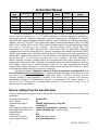
Device
type
Temperature
Humidity
Pressure
Computed
values
Output
Galvanic isolated
output
T0318
✓
-
-
-
RS232
-
T0418
✓
-
-
-
RS485
✓
T3318
✓
✓
-
✓
RS232
-
T3418
✓
✓
-
✓
RS485
✓
T7318
✓
✓
✓
✓
RS232
-
T7418
✓
✓
✓
✓
RS485
✓
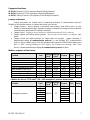
Devices are designed for indoor applications. By device type (see previous table) they can
measure ambient temperature at °C or °F, relative humidity of air without aggressive ingredients or
atmospheric pressure. Measured temperature and relative humidity are recomputed to humidity
expression: dew point temperature, absolute humidity, specific humidity, mixing ratio and specific
enthalpy. Devices T7318 and T7418 support atmospheric pressure measurement at hPa, PSI, inHg,
mBar, oz/in
2
, mmHg, inH
2
O or kPa. They support pressure correction for altitude setting (offset).
Unit choice is provided by User’s software – see later. Devices T0318, T3318 and T7318
communicate via link RS232, devices T0418, T3418 and T7418 via link RS485. Supported
communication protocols are Modbus RTU, protocol compatible with standard Advantech-ADAM,
ARION and communication with HWg–Poseidon devices. Devices are preset from manufacturer to
Modbus RTU communication protocol. If you would like to use different communication protocol
then Modbus RTU, it is necessary preset them throw user’s software – see latter. Temperature,
relative humidity eventually pressure sensors are non-removable device parts, pressure sensor is
placed inside the electronic case. Measured and computed values are optionally shown on dual line
LCD display. If there are two values displayed at one LCD line, they are periodically switched
between both readings with period of 4 seconds. Display can be switched OFF totally too. Please
read instruction manual before the first device connection.
Use user’s software Tsensor for setting of all device parameters (recommended). It is
free to download at www.cometsystem.cz. It supports make the adjustment of the device too. This
procedure is described at file „Calibration manual.pdf“ which is installed commonly with the
software. Change of some parameters is possible to do without user’s software with Windows
hyperterminal (change of communication protocol, its parameters, LCD display setting). It is
described in file “Description of communication protocols of Txxxx series” which is free to
download at the same address.
Device setting from the manufacturer
If special setting was not required in the order device is set from the manufacturer to the following
parameters:
communication protocol: Modbus RTU
device address: 01
communication speed: 9600Bd, without parity, 2 stop bits
display: switched ON
value displayed at higher line: temperature (temperature / pressure) – by device type
value displayed at lower line: relative humidity only – by device type
temperature unit: °C
pressure unit: hPa
correction for altitude: 0 hPa(absolute pressure)
preset computed value: dew point temperature

IE-SNC-TX3(4)18-07
3
Device installation
Devices are designed for indoor applications. It is recommended to mount them on universal
wiring box (common installation box KU68) with using two enclosed mounting screws. For correct
function there is necessary to find proper device place. It shouldn’t be placed at places where it can
be affected by sunshine, near radiators, heating elements and other heat sources, air handlers,
windows, doors, into racks and shelves and similar places. For buildings with less thermal
insulation there is not suitable to place them on external walls of building. If there are
communication conductors placed into conduit, there is strongly recommended make it caulk, to
restrict air flow around device.
Connect cables to terminals with respecting the signal polarity (see figure). Terminals are
self-clamping and can be opened by a suitable screwdriver. For the opening, insert the screwdriver
to upper terminal hole and lever by him.
There are two ways, how to power devices with RS232 interface. They can be powered
either from master device or from external power source. For powering from master device RS232
interface there is necessary to interconnect DTR and RTS signals with the device. For powering
from external power source, there is necessary to connect positive power terminal to DTR into
device terminal only and then do NOT interconnect DTR and RTS with master device.
Devices with RS232 interface:
Terminal
Connect to ( female connector CANNON 9 termination )
GND
Shielding, power source ground (PIN 5)
Tx
Output data for master device, transmit (PIN 2)
Rx
Input data from master device, receive (PIN 3)
RTS
Connect with RTS signal to master device (PIN 7), eventually o not connect
DTR
Connect with DTR signal to master device (PIN 4) or connect positive power terminal from
external power source
Devices with RS485 interface contain “doubled” connection terminals to provide continuous
connection of next RS485 devices. Terminals description:
Terminal
Connect to
A+, B-
RS485 communication line
Shielding of communication line
+U, GND
Power source positive terminal, power source ground
For devices with RS485 interface here is recommended to use shielded twisted copper cable
(e.g. SYKFY), maximal length 1200m. The cable must be located at indoor rooms.
Nominal cable impedance should be 100 Ω, loop resistance max. 240 Ω, cable capacity max.
65 pF/m. Suitable cable is e.g. SYKFY 2x2x0.5 mm
2
, where one wire pair serves for the device
powering and the other pair for communication link.
The cable should be led in one line, i.e. NOT to „tree“ or „star“. Termination resistor should
be located at the end. For short distance other topology is allowed. Terminate the network by a
termination resistor. The value of the resistor is recommended about 120 Ω. For short distance
termination resistor can be left out. The cable should not be led in parallel along power cabling.
Safety distance is up to 0.5 m, otherwise undesirable induction of interference signals can appear.
The same for devices with RS232 interface, but a maximal length is restricted to 15 m and
allow connect only one device.
Electrical system (wiring) may do only worker with required qualification by rules in
operation.

IE-SNC-TX3(4)18-07
4
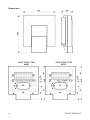
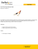
Dimensions
T0418, T3418, T7418
RS485
T0318, T3318, T7318
RS232

IE-SNC-TX3(4)18-07
5
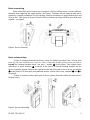
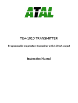
Device mounting
Firstly mount back part of device onto wiring box with two holding screws. Connect cables to
terminals with respecting the signal polarity (see figure). Terminals are self-clamping and can be
opened by a suitable screwdriver. For the opening, insert the screwdriver to upper terminal hole and
lever by him. Then insert front part of device firstly at bottom into hinge and then press both parts
together – see figure1
Figure1: Device mounting
Device demounting
If there is necessary demount the device, insert flat bladed screwdriver max. 3.5 mm wide
from top side into middle device’s air hole. There is fastening member placed, insert screwdriver
beyond the fastening member about 2 cm deep – number at the picture. Then slightly move
screwdriver in arrow direction as shown at the picture. It unlock fastening member and the
device is partially opened. Remove the screwdriver and take front part of device at top, see number
at the picture. Pull front part with pendulum motion, remove front cover, numbers and at
the picture.
If there is necessary remove back part of device, please disconnect cables and unscrew two
holding screws.
Figure2: Device demounting

IE-SNC-TX3(4)18-07
6
Button and jumper - placing
Button is placed behind small hole on the left side of the device (front
view). For button pressing use thin instrument, for example paper clip. Button
function is described later. Jumper is available only after the front part of device
is demounted. Then look at the back side of demounted front part. Jumper is
placed at the right bottom corner (at the same side as button). Jumper function is
described later.
Info mode
If in doubt of setting of installed device, verification of its address is enabled even without
using computer. Devices with RS232 interface have address always set to one.
Power should be connected. Shortly press Button (jumper should be opened). Actual adjusted
address of the device is displayed on LCD display at decimal base, for HWg-Poseidon’s
communication protocol there is shown number corresponding with ASCII address code. Next press
of button exits info mode and actual measured values are displayed.
Note: No measurement and communication is possible during info mode. If device stays in info
mode for longer than 15 s, device automatically returns to measuring cycle.
Setting of pressure correction for altitude
For devices T7318 and T7418 only! If there is necessary to read value of atmospheric pressure
corrected with respect to altitude, it is possible to set corresponding pressure offset for this altitude.
It is possible to do it with Users software. This value is then automatically added to measured
pressure value. The resultant value of pressure with added correction for altitude must be between
300 hPa and 1350 hPa (from 4.351 PSI to 19.580 PSI). Outside this range device sends value of
Error 2!
Description of communication protocols
Detailed description of each communication protocols including examples of communication
is available in individual document “Description of communication protocols of Txxxx series”
which is free to download at www.cometsystem.cz.
Note: After switching ON the power of the device it can last up to 2 s before the device starts to
communicate and measure!
Modbus RTU
Control units communicate on master-slave principle in half-duplex operation. Only master
can send request and only addressed device responds. During sending of request no other slave
station should respond. During communication, data transfer proceeds in binary format. Each Byte
is sent as eight bit data word in format: 1 start bit, data word 8 bit (LSB first), 2 stop bits
1
, without
parity. Device supports communication speed from 110Bd to 115200Bd.
Sent request and response have syntax: ADDRESS OF DEVICE – FUNCTION – Modbus
CRC
1
Device sends two stop bits, for receive one stop bit is enough.

IE-SNC-TX3(4)18-07
7
Supported functions
03 (0x03): Reading of 16-bit registers (Read Holding Registers)
04 (0x04): Reading of 16-bit input gates (Read Input Registers)
16 (0x10): Setting of more 16-bit registers (Write Multiple Registers)
Jumper and button
Jumper and button are located next to connection terminals. If communication protocol
Modbus is selected the function of jumper and button is as follows:
• Jumper opened – device memory is protected from writing, from device side it is only
enabled to read measured value, writing to memory is disabled (no change of device address,
communication speed and LCD setting is enabled)
• Jumper closed – writing to device memory is enabled by means of User’s software
• Jumper opened and button shortly pressed – device goes to Info mode, see chapter „Info
mode“
• Jumper closed and button pressed for longer than six seconds – causes restoring of
manufacturer setting of communication protocol, i.e. sets Modbus RTU communication
protocol, device address sets to 01h and communication speed to 9600Bd (after button press
there is “dEF” message blinking at LCD display. Six seconds later message “dEF” stays
shown, it means manufacturer setting of communication protocol is done).
Modbus registers of the device
Variable
Unit
Address
[hex]
X
Address
[dec]
X
Format
Size
Status
Measured temperature
[°C] [°F]*
0x0031
49
Int*10
BIN16
R
Measured relative humidity
[%]
0x0032
50
Int*10
BIN16
R
Computed value
*
[*]
0x0033
51
Int*10
BIN16
R
Address of device
[-]
0x2001
8193
Int
BIN16
R/W*
Code of communication speed
[-]
0x2002
8194
Int
BIN16
R/W*
Serial number of device Hi
[-]
0x1035
4149
BCD
BIN16
R
Serial number of device Lo
[-]
0x1036
4150
BCD
BIN16
R
Version of Firmware Hi
[-]
0x3001
12289
BCD
BIN16
R
Version of Firmware Lo
[-]
0x3002
12290
BCD
BIN16
R
Addition for devices T7310 and T7410 - with atmospheric pressure measurement
Variable
Unit*
Address
[hex]
X
Address
[dec]
X
Format
Size
Status
Atmospheric pressure
hPa
0x0034
52
Int*10
BIN16
R
PSI
Int*1000
inHg
Int*100
mBar
Int*10
oz/in
2
Int*10
mmHg
Int*10
inH
2
O
Int*10
kPa
Int*100

IE-SNC-TX3(4)18-07
8
Since FW version 02.44 there is possibility to read the all computed values from registers:
Variable
Unit
Address
[hex]
X
Address
[dec]
X
Format
Size
Status
Dew point temperature
[°C] [°F]*
0x0035
53
Int*10
BIN16
R
Absolute humidity
[g/m
3
]
0x0036
54
Int*10
BIN16
R
Specific humidity
[g/kg]
0x0037
55
Int*10
BIN16
R
Mixing ratio
[g/kg]
0x0038
56
Int*10
BIN16
R
Specific enthalpy
[kJ/kg]
0x0039
57
Int*10
BIN16
R
Explanation:
• * depends on device setting (by User’s software)
• Int*10 register is in format integer*10
• R register is designed only for reading
• W* register is designed for writing, for details see file “Description of communication
protocols of Txxxx series”
•
X
register addresses are indexed from zero – register 0x31 is physically sent as value
0x30, 0x32 as 0x31 (zero based addressing).
Note: In case there is a need for reading of measured values from the device with higher
resolution than one decimal, measured values in device are stored also in „Float“ format, which
is not directly compatible with IEEE754.
Protocol compatible with Advantech-ADAM standard
Control units communicate on master-slave principle in half-duplex operation. Only master
can send requests and only addressed device responds. During sending request any of slave devices
should respond. During communication data is transferred in ASCII format (in characters). Each
Byte is sent as two ASCII characters. Device supports communication speed from 1200Bd to
115200Bd, parameters of communication link are 1 start bit + eight bit data word (LSB first) +
1 stop bit, without parity.
Jumper
Jumper is located next to connection terminals. If communication protocol compatible with
standard Advantech-ADAM is selected, its function is the following:
• If jumper during switching ON the power is closed, device always communicates with
following parameters regardless stored setting in the device:
communication speed 9600 Bd, without check sum, device address 00h
• If jumper during switching ON the power is not closed, device communicates in accordance
with stored setting.
• If jumper is closed during device operation, device temporarily changes its address to 00h, it
will communicate in the same communication speed as before closing jumper and will
communicate without check sum. After jumper is opened setting of address and check sum
is reset in accordance with values stored in the device.
• Communication speed and check sum are possible to change only if jumper is closed.
• Jumper closed and button pressed for longer than six seconds – causes restoring of
manufacturer setting of communication protocol, i.e. sets Modbus RTU communication
protocol, device address sets to 01h and communication speed to 9600Bd (after button press
there is “dEF” message blinking at LCD display. Six seconds later message “dEF” stays
shown, it means manufacturer setting of communication protocol is done).

IE-SNC-TX3(4)18-07
9
For communication with device which measure more than one value, there is necessary to
add at the end of command the number of communication channel, where the measured value is
mapped. Command for value reading is #AAx(CRC) cr, where AA is device address, x is number
of communication channel, CRC is check sum (can be used or not).
Measured value
Number of communication channel
Temperature
0
Relative humidity
1
Computed value
2
Atmospheric pressure
3
Command #AA(CRC) cr for reading all measured values at once is supported for multi-
channel devices since firmware version 02.60.
Response: > (temperature)(relative humidity)(dew point temperature)(absolute humidity)
(specific humidity)(mixing ratio)(specific enthalpy)(atmospheric pressure)cr
ARION communication protocol - AMiT company
The device supports communication protocol ARiON version 1.00. For more details see file
“Description of communication protocols of Txxxx series” or www.amit.cz.
Communication with HWg Poseidon units
Device supports communication with HWg-Poseidon units. For communication with this
unit set the device with setup software TSensor to communication protocol HWg–Poseidon and set
correct device address. This communication protocol supports read temperature at °C, relative
humidity, one of computed value (dew point temperature or absolute humidity) and barometric
pressure at kPa (depended by device type). For atmospheric pressure correction to altitude setting
there is Users software Tsensor.
Jumper and button
If communication with HWg Poseidon unit is selected, the function of jumper and button is as
follows:
• Jumper opened and button shortly pressed – device goes to Info mode, see chapter „Info
mode“.
• Jumper closed and button pressed for longer than six seconds – causes restoring of
manufacturer setting of communication protocol, i.e. sets Modbus RTU communication
protocol, device address sets to 01h and communication speed to 9600Bd - after button press
there is “dEF” message blinking at LCD display. Six seconds later message “dEF” stays
shown, it means manufacturer setting of communication protocol is done.

IE-SNC-TX3(4)18-07
10
Error States of the device
Device continuously checks its state during operation. In case error is found LCD displays
corresponding error code:
Error 0
First line displays „Err0“. Check sum error of stored setting inside device’s memory. This error
appears if incorrect writing procedure to device’s memory occurred or if damage of calibration data
appeared. At this state device does not measure and calculate values. It is a serious error, contact
distributor of the device to fix.
Error 1
Measured or calculated value except in pressure is over upper limit of allowed full scale range.
There is a reading „Err1“ on LCD display. Value read from the device is +999.9. (for pressure
reading there is +999.9 hPa correct value)
This state appears in case of:
• Measured temperature is higher than approximately 600°C (i.e. high non-measurable
resistance of temperature sensor, probably opened circuit).
• Relative humidity is higher than 100%, i.e. damaged humidity sensor, or humidity
calculation of humidity is not possible (due to error during temperature measurement)
• Computed value – calculation of the value is not possible (error during measurement of
temperature or relative humidity or value is over range)
Error 2
There is a reading „Err2“ on LCD display. Measured or calculated value is below lower limit of
allowed full scale range. Value read from the device is -999.9.
This state appears in case of:
• Measured temperature is lower than approximately -210°C (i.e. low resistance of
temperature sensor, probably short circuit).
• Relative humidity is lower than 0%, i.e. damaged sensor for measurement of relative
humidity, or calculation of humidity is not possible (due to error during temperature
measurement)
• Measured pressure value with added correction for altitude is outside of range from
300 hPa to 1350 hPa (from 4.351 PSI to 19.580 PSI) or the pressure sensor is damaged.
Please check setting of pressure correction for altitude with User’s software.
• Computed value – calculation of computed value is not possible (error during measurement
of temperature or relative humidity)
Error 3
There is a reading „Err3“ on LCD display upper line. Error of internal A/D converter appeared
(converter does not respond, probably damage of A/D converter). This error does NOT affect
pressure measurement. Rest values are NOT measured. It is a serious error, contact distributor of the
device.
Error 4
There is a reading „Err4“ on LCD display. It is internal device error during pressure sensor
initialization. Under this condition device does NOT measure atmospheric pressure. Value read
from device is -999.9. Pressure sensor is probably damaged. It is a serious error, contact distributor
of the device.

IE-SNC-TX3(4)18-07
11
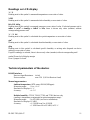
Readings on LCD display
°C, °F
Reading next to this symbol is measured temperature or error state of value.
%RH
Reading next to this symbol is measured relative humidity or error state of value.
hPa, PSI, inHg,
Reading next to this symbol is measured pressure or error state of value. If selected pressure unit is
mBar or oz/in
2
or mmHg or inH
2
O or kPa, there is shown only value (number) without
corresponding pressure unit!
°C / °F DP
Reading next to this symbol is calculated dew point temperature or error state of value.
g/m
3
Reading next to this symbol is calculated absolute humidity or error state of value.
g/kg
Reading next to this symbol is calculated specific humidity or mixing ratio (depends on device
setting) or error state of value.
If specific enthalpy is selected, there is shown only value (number) without corresponding unit!
symbol 3 near by left display margin
Is on if jumper is closed.
Technical parameters of the device:
RS 485 Interface:
Receiver-Input Resistance: 96 kΩ
Devices on bus: max. 256 (1/8 Unit Receiver Load)
Measuring parameters:
Ambient temperature (RTD sensor Pt1000/3850ppm):
Measuring range: -10 to +50 °C
Resolution of display: 0.1 °C
Accuracy: ± 0.5 °C
Relative humidity - T3318, T3418, T7318 and T7418 devices only
(reading is temperature compensated at entire temperature range):
Measuring range: 5 to 95 %RH (see Device installation)
Resolution of display: 0.1 %RH
Accuracy: ± 2.5 %RH from 5 to 60 %RH,
± 3 %RH from 60 to 95 %RH, at 23 °C

IE-SNC-TX3(4)18-07
12
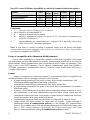
Atmospheric pressure (T7318, T7418 only):
Unit
hPa, mBar
PSI
mmHg
inHg
inH
2
O
oz/in
2
kPa
Range
600.0
8.70
450.0
17.72
240.9
139.2
60.00
1100.0
15.95
825.1
32.48
441.6
255.3
110.00
Display resolution
0.1
0.001
0.1
0.01
0.1
0.1
0.01
Measurement accuracy
T=23 °C
±1.3
±0.02
±1.0
±0.04
±0.5
±0.3
±0.13
0≤T≤40°C
±1.5
±0.02
±1.1
±0.04
±0.6
±0.3
±0.15
Else
±2.0
±0.03
±1.5
±0.06
±0.8
±0.5
±0.20
The value computed from ambient temperature and relative humidity (T3318, T3418, T7318
and T7418 devices only):
Display resolution: 0.1 °C
You can choice one of the next value:
Dew point temperature
Range: -60 to +80 °C (-76 to 176 °F)
Accuracy: ±1.5 °C (±2,7 °F) at ambient temperature T < 25°C (77°F) and relative
humidity RH >30%, for more details see graphs below

IE-SNC-TX3(4)18-07
13
Absolute humidity
Range: 0 to 400 g/m
3
Accuracy: ±1,5g/m
3
at air temperature T < 25°C (104 °F), for more details see
graphs below
Specific humidity
2
Accuracy: ±2g/kg at air temperature T < 35°C (95°F)
Range: 0 to 550 g/kg
Mixing ratio
2
Accuracy: ±2g/kg at air temperature T < 35°C (95°F)
Range: 0 to 995 g/kg
Specific enthalpy
2
Accuracy: ± 3kJ/kg at air temperature T < 25°C (77°F)
Range: 0 to 995 kJ/kg
3
The values computed from ambient temperature and relative humidity including their
accuracy you can exactly determine by the program Conversions. It is free to
download at www.cometsystem.cz.
Response time:
temperature: air flow approximately 0.3 m/s t90 < 12 min
No air flow t90 < 25 min
relative humidity: t90 < 30 s (air flow approximately 1 m/s, relative humidity step
65 %RH, constant temperature)
atmospheric pressure
4
: t90 <44 s
Recommended calibration interval: T0318, T0418: 2 years
Rest types: 1 year
2
This value depends on the barometric pressure. If device doesn’t support pressure measurement, then
constant value stored inside device memory is used. Default value preset by manufacturer is 1013hPa and
can be changed by user’s software.
3
This maximum is reached under conditions about 70°C/100%RH or 80°C/70%RH
4
There is possible to change response time. For more details see file “Description of calibration and adjustment
procedure.pdf”, which is installed together with Users software..

IE-SNC-TX3(4)18-07
14
Measuring interval and LCD display refresh: 0.5 s, atmospheric pressure 2 s
Power: 9 to 30 V dc
Consumption: T0318, T3318, T7318 (RS232) 6mA
T0418, T3418, T7418 (RS485) max 0.5 W
Protection: IP20
Operating conditions:
Operating temperature range: -10 to +50 °C
Operating humidity range: 0 to 100 %RH (without condensation)
Outer characteristics in accordance with Czech National Standart 33-2000-3, normal
environment with the specifications: AE1, AN1, BE1
Electromagnetic compatibility: complies EN 61326-1
Storing conditions: temperature -30 to +80 °C, humidity 0 to 100 %RH without condensation
Not allowed manipulations: It is not allowed to operate the device under other than specified
conditions in technical parameters. Devices are not designed for locations with chemically
aggressive environment. Temperature and humidity sensors must not be exposed to direct
contact to water or other liquids. Do not use the device in an explosive environment.
Dimensions: 106 x 88 x 33 (h x l x d)
Weight: approximately 150 g
Material of the case: ABS
End of operation
Device itself (after its life) is necessary to liquidate ecologically!
Technical support and service
Technical support and service is provided by distributor. For contact see warranty certificate.

IE-SNC-TX3(4)18-07
15
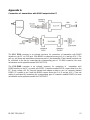
Appendix A
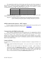
Connection of transmitters with RS485 output to the PC
The ELO E214 converter is an optional accessory for connection of transmitter with RS485
interface to the PC via USB port. Link RS485 is connected across pin 9 A(+) and pin 8 B(-). The
pull up, pull down and termination resistors are part of the transmitter. These internal resistors can
be connected to the bus by connecting the corresponding pins of CANON connector (for more
information see the operation manual for ELO E214).
The ELO E06D converter is an optional accessory for connection of transmitter with
RS485 interface to the PC via serial port RS232. Connector marked RS232 connect directly to the
PC. Power voltage +6V DC from an external acdc adapter connect to pin 9 of connector marked
RS485, 0V connect to pin 5 and link RS485 connect across pin 3 A(+) and pin 4 B(-). Time out
setting is performed by connecting the corresponding pins of connector marked RS485 (for more
information see the operation manual for ELO E06D).
-
 1
1
-
 2
2
-
 3
3
-
 4
4
-
 5
5
-
 6
6
-
 7
7
-
 8
8
-
 9
9
-
 10
10
-
 11
11
-
 12
12
-
 13
13
-
 14
14
-
 15
15


Comet T0318 User manual
- Category
- Measuring, testing & control
- Type
- User manual
Ask a question and I''ll find the answer in the document
Finding information in a document is now easier with AI
Related papers
Other documents
-
Testo 511 Short Manual
-
 StarTech.com TX3EXT12 Datasheet
-
Advantech 5000 Series User manual
-
Mircom LT-978 RB-MD-955 TX3-ER-8 Installation guide
-
-
Sytech SY-Z19M4 User manual
-
 Atal TEA-101D User manual
-
Testo 510 User manual
-
Mircom LT-6618 TX3-CX-1 Installation guide
-

