Celestron CGEM DX Owner's manual
- Category
- Telescopes
- Type
- Owner's manual
This manual is also suitable for

INSTRUCTION MANUAL
CGEM DX CoMputErizED Mount
ENGLISH

Table of ConTenTs
Introduction ..................................... 1
Warning
...................................... 1
Assembly
....................................... 3
Setting up the Tripod
............................ 3
Attaching the Accessory Tray
..................... 3
Attaching the Azimuth Adjustment Knobs
............ 3
Attaching the Equatorial Mount
.................... 3
Installing the Counterweight Bar
................... 4
Installing the Counterweight
...................... 4
Attaching the Hand Control Holder
................ 5
Attaching an Optical Tube to the Mount
............. 5
Moving the Telescope Manually
.................... 5
Balancing the Mount in R.A. ....................... 5
Balancing the Mount in DEC
....................... 6
Adjusting the Mount
............................. 6
Adjusting the Mount in Altitude
................. 6
Adjusting the Mount in Azimuth
................. 6
Powering the Mount
............................. 6
Hand Control
.................................... 6
Hand Control Operation
....................... 7
Alignment Procedures
........................... 7
Startup Procedure
............................... 8
Two Star Align
.................................. 8
East/West (E/W) Filtering
. . . . . . . . . . . . . . . . . . . . . . . 9
Quick-Align
.................................. 10
Last Alignment
................................ 10
Re-Alignment
................................. 10
Object Catalog
................................ 10
Selecting an Object
.......................... 10
Slewing to an Object
......................... 10
Finding Planets
............................. 10
Tour Mode
..................................11
Constellation Tour
............................11
Direction Buttons
.............................11
Rate Button
.................................11
Setup Procedures
...............................11
Tracking Mode
...............................11
Tracking Rate
................................11
Date / Time
..................................11
User Defined Objects
..........................11
Get RA/DEC
............................... 12
Goto R.A/ Dec .............................. 12
Identify
.................................... 12
Precise GoTo
................................. 12
Scope Setup Features
.......................... 12
Setup Time-Site
............................. 12
Anti-backlash
............................... 12
Filter Limits
................................ 13
Direction Buttons
........................... 13
Goto Approach
............................. 13
Autoguide Rate
............................. 13
OTA Orientation
............................ 14
Meridian
. . . . . . . . . . . . . . . . . . . . . . . . . . . . . . . . . . . 14
Mount Settings
............................. 14
RA Limits
.................................. 14
Utility Features
................................ 15
Calibrate Mount
............................ 15
Home Position
.............................. 15
Light Control
............................... 15
Factory Settings
............................ 15
Version
.................................... 15
Get Axis Position
............................ 15
Goto Axis Position
........................... 15
Hibernate
.................................. 15
Sun Menu
.................................. 15
Scrolling Menu
.............................. 15
Set Mount Position
............................. 15
Turn On/Off GPS
............................ 15
Turn On/Off RTC
............................ 15
Periodic Error Correction (PEC)
................. 16
Astronomy Basics
............................... 18
The Celestial Coordinate System
.................. 18
Motion of the Stars
............................. 18
Polar Aligning the Mount
........................ 18
All-Star Polar Align
. . . . . . . . . . . . . . . . . . . . . . . . . . . 19
Finding the North Celestial Pole
.................. 20
Optional Accessories
............................ 21
Appendix A – Technical Specifications
.............. 22
Appendix B - Glossary Of Terms
................... 22
Appendix C - RS-232 Connection
.................. 25
Appendix D – Maps Of Time Zones
................ 27
Sky Maps
...................................... 29

1
InTroduCTIon
Congratulations on your purchase of the Celestron CGEM DX
Series Mount! The CGEM DX series continues in Celestron’s
proud tradition combining large aperture optics with the
sophistication and ease of use of our computerized
GoTo mount.
If you are new to astronomy, you may wish to start off by using
the built-in Sky Tour feature, which commands the mount to
find the most interesting objects in the sky and automatically
slews to each one. Or if you are an experienced amateur, you
will appreciate the comprehensive database of over 40,000
objects, including customized lists of all the best deep-sky
objects, bright double stars and variable stars. No matter your
level of experience, the CGEM DX mount telescopes will unfold
for you and your friends all the wonders of the Universe.
Some of the many standard features of the
telescope include:
• Fullyenclosedopticalencodersforpositionlocation.
• Ergonomicallydesignedmountthatdisassemblesinto
compact and portable pieces.
• Databaselterlimitsforcreatingcustomobjectlists.
• Storageforprogrammableuserdenedobjects;
and many other high performance features!
Take time to read through this manual before embarking on
your journey through the Universe. It may take a few observing
sessions to become familiar with your mount, so you should
keep this manual handy until you have fully mastered your
telescope’s operation. The hand control has built-in instructions
to guide you through all the alignment procedures needed to
have the telescope up and running in minutes. Use this manual
in conjunction with the on-screen instructions provided by the
hand control. The manual gives detailed information regarding
each step as well as needed reference material and helpful hints
guaranteed to make your observing experience as simple and
pleasurable as possible.
The CGEM DX mount is designed to give you years of fun
and rewarding observations. However, there are a few things
to consider before using your telescope that will ensure your
safety and protect your equipment.
WarninG
• Neverlookdirectlyatthesunwiththenaked
eyeorwithatelescope(unlessyouhavethe
propersolarlter).Permanentandirreversible
eye damage may result.
• Neveruseyourtelescopetoprojectanimageofthesunonto
any surface. Internal heat build-up can damage the telescope
and any accessories attached to it.
• NeveruseaneyepiecesolarlteroraHerschelwedge.
Internal heat build-up inside the telescope can cause these
devices to crack or break, allowing unfiltered sunlight to pass
through to the eye.
Never leave the telescope unsupervised, either when
children are present or adults who may not be familiar with
the correct operating procedures of your telescope.

2
Figure 2-1 – CgeM DX Mount
Mount
1. Equatorial Mount
2. Latitude Adjustment
Knob
3
. Tripod
4. Hand Control
5. Tripod Center Leg
Brace/Accessory Tray
6.
Counterweight(s)
7. Counterweight Bar
8. Telescope Mounting
Platform
Control Panel
A. On/Off Switch
B. 12v Input Jack
C. Hand Control Port
D. AUX Port
E. Autoguider Port
1
2
3
4
5
6
7
8
A
BC
D E

3
assembly
The Celestron CGEM DX mount is shipped in three main boxes.
In separate boxes are the following:
• EquatorialMountwithHandControl,CounterweightBar
and tripod adapter plate included
• Tripod
• Counterweight(s)
Remove all the pieces from their respective boxes and place on
a flat, clear work area. A large floor space is ideal. When setting
up your Celestron mount you must start with the tripod and
work up from there. These instructions are laid out in the order
each task should be performed.
SEttinG up thE tripoD
The CGEM DX tripod comes with an all metal center leg brace /
accessory tray to give rock solid support to the mount.
The tripod comes fully assembled with a metal plate, called the
tripod head that holds the legs together at the top. In addition,
there is a central rod that extends down from the tripod head
that attaches the accessory tray between the legs. To set up
the tripod:
1. Stand the tripod upright and pull the tripod legs apart until
each leg is fully extended. The tripod will now stand by itself.
Once the tripod is set up, you can adjust the height at which
it stands.
2. Loosen the lever on the leg clamp so that the tripod leg can
be adjusted.
3. Slide the center portion of the tripod leg away from the
tripod head until it is at the desired height.
4. Tighten the levers on each leg clamp to hold the legs
in place.
5. Once that it is fully assembled, rotate the tripod so that one
of the legs is pointing roughly towards north.
attaChinG thE aCCESSory tray
1. Slide the accessory tray over the central rod so that the three
cup indents are pushing against the inside of the tripod legs.
2. Thread the accessory tray knob on to the central rod
and tighten.
To transport your tripod, remove the knob and lower the
accessory tray far enough to rotate it until the three recesses
line up with each leg. Collapse the legs so that each leg falls
into one of the recesses. Secure the legs together with the
nylon strap attached to the tripod leg.
attaChinG thE aziMuth aDjuStMEnt KnobS
To ensure safe shipment of your CGEM mount, the Azimuth
Adjustment Knobs have been removed from the mount and will
need to be attached.
Before securing the mount to the tripod as shown in Fig. 2-4:
1. Locate the Azimuth Adjustment Knobs from the box
containing the CGEM DX mount.
2. Thread one knob into each of the holes located on either
side of the mount.
3. Only thread the knobs about half way in, leaving enough
space for the tripod Alignment Peg which will need to fit
between the screw tips.
attaChinG thE Equatorial Mount
The equatorial mount allows you to tilt the telescope’s axis of
rotation so that you can track the stars as they move across the
sky. The CGEM DX mount is a German equatorial mount that
attaches to the tripod. On one side of the tripod head there
is a metal alignment peg for aligning the mount. This side of
the tripod will face north when setting up for an astronomical
observing session. Before attaching the equatorial head
mount to the tripod, the tripod mounting adapter must first be
attached to the tripod:
1. Place the tripod mounting adapter over the top of the
tripod head.
2. Rotate the adapter so that the holes line up with holes along
the side of the tripod head. Make sure the alignment peg is
over the tripod leg that you want to be facing north
when aligning.
3. Secure the mounting adapter to the tripod head using the
three screws and washers provided.
4. Thread the center support rod up through the center of the
tripod mounting adapter until the threads end.
The center support rod should now be captured by the
tripod mounting adapter and is ready to accept the
equatorial mount.
Figure 2-3
Figure 2-2
Accessory
Tray / Leg
Support
Leg
Clamp Lock
Levers

4
5. Locate the azimuth adjustment screws on the equatorial
mount (Fig 2-3).
6. Retract the screws so they do not extend into the azimuth
housing on the mount.
7. Hold the equatorial mount over the tripod adapter so that
the azimuth housing is above the metal peg.
8. Lower the equatorial mount on the tripod so that the two
are flush.
9. Thread the knob (attached to the central rod) on the
underside of the tripod head into the bottom of the
equatorial mount to hold it firmly in place.
inStallinG thE CountErWEiGht bar
To properly balance the telescope, the mount comes with a
counterweight bar and at least one counterweight (depending
on model). To install the counterweight bar:
1. Locate the counterweight bar locking nut from the box
containing the CGEM DX mount (see Fig 2-5).
2. Thread the counterweight bar through the rounded end of
locking nut until the threads pass all the way through and the
locking nut can go no further.
3. Locate the opening in the equatorial mount on the DEC axis.
4. Thread the counterweight bar into the opening until tight.
5. Tighten the counterweight bar lock nut fully for
added support.
Once the bar is securely in place you are ready to attach
the counterweight.
Since the fully assembled telescope can be quite
heavy, position the mount so that the polar axis is
pointing towards north before the tube assembly and
counterweights are attached. This will make the polar
alignment procedure much easier.
inStallinG thE CountErWEiGht
Depending on which telescope model you have, you will
receive either one, two or three counterweights. To install
the counterweight(s):
1. Orient the mount so that the counterweight bar points
toward the ground
2. Remove the counterweight safety screw on the end of the
counterweight bar (i.e., opposite the end that attaches to
the mount).
3. Loosen the locking screw on the side of the counterweight.
4. Slide the counterweight onto the shaft (see Figure 2-5).
5. Tighten the locking screw on the side of the weight to hold
the counterweight in place.
6. Replace the counterweight safety screw.
Figure 2-4
Equatorial
Mount
Alignment
Peg
Tripod
Mounting
Adapter
Heavy
Duty
Tripod
Center
Support
Rod
Tripod
Head
Figure 2-5 – Mount shown with two Counterweights
(CgeM DX 1400)
Counterweight
Bar Locking Nut
Counterweight Bar
Locking
Screw
Counterweight
Safety Screw

5
attaChinG thE hanD Control holDEr
The telescope comes with a hand control holder to place the
computerized hand control. The hand control holder comes
attached to the tripod leg and can be easily removed for
convenient use. To use the hand control plug the phone jack
connector into the hand control port labeled on the electronics
control panel.
attaChinG an optiCal tubE to thE Mount
The CGEM DX mount is equipped with a mounting plate that
accepts the Celestron CGE style (3”) dovetail bar. Before you
attach the optical tube, make sure that the declination and
rightascensionclutchknobsaretight(seeFigure2-8)and
thecounterweight(s)aresecurelyinstalled. This will ensure
that the mount does not move suddenly while attaching the
telescope. To mount the telescope tube:
1. Loosen the mounting screw on the side of the telescope
mounting platform. This allows you to slide the dovetail bar
onto the mount.
2. Remove the safety screw located at the front of the
dovetail bar.
3. Slide the dovetail bar on the telescope tube into the
mounting platform of the mount.
4. Tighten the mounting screw on the side of the mounting
platform to hold the telescope in place.
Now that the optical tube is securely in place, the visual
accessories can now be attached to the telescope.
MovinG thE tElESCopE Manually
In order to properly balance your telescope, you will need to
move your telescope manually at various portions of the sky to
observe different objects. To make rough adjustments, loosen
the R.A. and DEC clutch knobs slightly and move the telescope
in the desired direction.
Both the R.A. and DEC axis have lock levers to clutch down
each axis of the telescope. To loosen the clutches on the
telescope, rotate the lock levers counterclockwise.
balanCinG thE Mount in r.a.
To eliminate undue stress on the mount, the telescope should
be properly balanced around the polar axis. Proper balancing is
crucial for accurate tracking. To balance the mount:
1. Verify that the telescope is securely attached to the
telescope mounting platform.
2. Loosen the R.A. lock lever and position the telescope off to
one side of the mount. The counterweight bar will extend
horizontally on the opposite side of the mount.
3. Release the telescope — GRADUALLY — to see which way
the telescope “rolls.”
4. Loosen the set screws on the side of the counterweight so it
can be moved the length of the counterweight bar.
5. Move the counterweight to a point where it balances the
telescope (i.e., the telescope remains stationary when the
R.A. clutch knobs are loose).
6. Tighten the screw on the counterweight to hold it in place.
While the above instructions describe a perfect balance
arrangement, there should be a SLIGHT imbalance to ensure
the best possible tracking. When the scope is on the west
side of the mount the counterweight should be slightly
imbalanced to the counterweight bar side. And when the
tube is on the east side of the mount there should be a slight
imbalance toward the telescope side. This is done so that the
worm gear is pushing against a slight load. The amount of the
Figure 2-7
Safety
Screw
Dovetail
Bar
Telescope
Mounting
Screw
Figure 2-8
DEC Lock
RA Lock
Figure 2-9
Figure 2-6
Hand Control
Holder

6
imbalance is very slight. When taking astrophotographs, this
balance process can be done for the specific area at which the
telescope is pointing to further optimize tracking accuracy.
balanCinG thE Mount in DEC
Although the telescope does not track in declination, the
telescope should also be balanced in this axis to prevent any
sudden motions when the DEC lock lever is loose. To balance
the telescope in DEC:
1. Loosen the R.A. clutch lock lever and rotate the telescope so
that it is on one side of the mount (i.e., as described in the
previous section on “Balancing the Mount in R.A.”).
2. Tighten the R.A. lock lever to hold the telescope in place.
3. Loosen the DEC clutch lock lever and rotate the telescope
until the tube is parallel to the ground.
4. Release the tube — GRADUALLY — to see which way it
rotates around the declination axis. DONOTLETGOOF
THE TELESCOPE TUBE COMPLETELY!
5. Slightly loosen the knobs that holds the telescope to the
mounting platform and slide the telescope either forward
or backward until it remains stationary when the DEC clutch
is loose. Do NOT let go of the telescope tube while the
knob on the mounting platform is loose. It may be necessary
to rotate the telescope so that the counterweight bar is
pointing down before loosening the mounting
platform screw.
6. Tighten the knobs on the telescope mounting platform to
hold the telescope in place.
Like R.A. balance, these are general balance instructions
and will reduce undue stress on the mount. When taking
astrophotographs, this balance process should be done for the
specific area at which the telescope is pointing.
aDjuStinG thE Mount
In order for a motor drive to track accurately, the telescope’s
axis of rotation must be parallel to the Earth’s axis of rotation, a
process known as polar alignment. Polar alignment is achieved
NOT by moving the telescope in R.A. or DEC, but by adjusting
the mount vertically, which is called altitude, and horizontally,
which is called azimuth. This section simply covers the correct
movement of the telescope during the polar alignment process.
The actual process of polar alignment, that is making the
telescope’s axis of rotation parallel to the Earth’s, is described
later in this manual in the section on “Polar Alignment
.”
Adjusting the Mount in Altitude
• Toincrease(raise) the latitude of the polar axis, turn the
rear latitude adjustment knob and loosen the front screw
(if necessary)
.
• Todecrease(lower) the latitude of the polar axis, turn the
rear latitude adjustment knob and tighten the front screw
(if necessary)
.
The latitude adjustment on the mount has a range from
approximately 15° to 70°.
It is best to always make final adjustments in latitude by moving
the mount against gravity (i.e. using the rear latitude adjustment
screw to raise the mount).
Adjusting the Mount in Azimuth
For rough adjustments in azimuth, simply pick up the telescope
and tripod and move it side to side until it is roughly pointing
towards north. For fine adjustments in azimuth:
1. Turn the azimuth adjustment knobs located on either side of
the azimuth housing (see Fig 2-10). While standing behind
the telescope, the knobs are on the front of the mount.
•Turningtherightadjustmentknobclockwisemovesthemount
toward the right.
•Turningtheleftadjustmentknobclockwisemovesthemount
to the left.
Both screws push off of the peg on the tripod head, which
means you may have to loosen one screw while tightening the
other. The screw that holds the equatorial mount to the tripod
may have to be loosened slightly.
Keep in mind that adjusting the mount is done during the polar
alignment process only. Once polar aligned, the mount must
NOT be moved. Pointing the telescope is done by moving the
mount in right ascension and declination, as described earlier in
this manual.
poWErinG thE Mount
The telescope mount can be powered by the supplied car
battery adapter or optional 12v AC adapter. Use only adapters
supplied by Celestron. Using any other adapter may damage
the electronics or cause the telescope not to operate properly,
and will void your manufacturer’s warranty.
1. To power the telescope with the car battery adapter (or 12v
AC adapter), simply plug the round post into the 12v outlet
on the electronic panel and plug the other end into your
cars cigarette lighter outlet or portable power supply (see
Optional Accessories
).
2. Turn on the power to the telescope by flipping the switch,
located on the electronics panel, to the “On” position.
Hand ConTrol
All Celestron computerized telescope come with a hand
control designed to give you instant access to all the functions
that your telescope has to offer. With automatic slewing to
over 40,000 objects, and common sense menu descriptions,
even a beginner can master its variety of features in just a few
observing sessions. Below is a brief description of the individual
components of the computerized hand controller:
1. LiquidCrystalDisplay(LCD)Window: Has a dual-line,
16 character display screen that is backlit for comfortable
viewing of telescope information and scrolling text.
Figure 2-10
Rear
Latitude
Adjustment
Knob
Front
Latitude
Adjustment
Screw
Azimuth
Adjustment
Knob

7
2. Align: Instructs the telescope to use a selected star or
object as an alignment position.
3. Direction Keys: Allows complete control of the telescope
in any direction. Use the direction keys to move the
telescope to the initial alignment stars or for centering
objects in the eyepiece.
4. Catalog Keys: The hand control has keys on the hand
control to allow direct access to each of the catalogs in its
database. The hand control contains the following catalogs
in its database:
Messier
— Complete list of all Messier objects.
NGC — Complete list of all the deep-sky objects in the
Revised New General Catalog.
Caldwell — A combination of the best NGC and
IC objects.
Planets — All 8 planets in our Solar System plus
the Moon.
Stars — A compiled list of the brightest stars from the
SAO catalog.
List — For quick access, all of the best and most popular
objects in the telescope’s database have been broken
down into lists based on their type and/or
common name:
Named Stars Common name listing of the brightest
stars in the sky.
Named Objects Alphabetical listing of over 50 of the most
popular deep sky objects.
Double Stars Numeric-alphabetical listing of the most
visually stunning double, triple and
quadruple stars in the sky.
Variable Stars Select list of the brightest variable
stars with the shortest period of
changing magnitude.
Asterisms A unique list of some of the most
recognizable star patterns in the sky.
CCD Objects A custom list of many interesting galaxy
pairs, trios and clusters that are well suited
for CCD imaging.
IC Objects A complete list of all the Index Catalog
deep-sky objects.
Abell Objects A custom list of the Abell Catalog
deep-sky galaxies.
Constellation A complete list of all 88 constellations.
5. Info: Displays coordinates and useful information about
objects selected from the telescope database.
6. Tour: Activates the tour mode, which seeks out all the best
objects for the current date and time, and automatically
slews the telescope to those objects.
7. Enter: Pressing Enter allows you to select any of the
telescope’s functions and accept entered parameters.
8. Undo: Undo will take you out of the current menu and
display the previous level of the menu path. Press Undo
repeatedly to get back to a main menu or use it to erase
data entered by mistake.
9. Menu: Displays the many setup and utilities functions such
as tracking rates and user defined objects and many others.
10. Scroll Keys: Used to scroll up and down within any of the
menu lists. A double-arrow will appear on the right side of
the LCD when there are sub-menus below the displayed
menu.Usingthesekeyswillscrollthroughthose
sub-menus.
11. Rate: Instantly changes the rate of speed of the motors
when the direction buttons are pressed.
12. RS-232 Jack: Allows you to interface with a computer and
control the telescope remotely.
Hand Control Operation
This section describes the basic hand control procedures
needed to operate all Celestron computerized telescopes.
These procedures are grouped into three categories:
Alignment, Setup and Utilities. The alignment section deals with
the initial telescope alignment as well as finding objects in the
sky;thesetupsectiondiscusseschangingparameterssuchas
trackingmodeandtrackingrate;nally,thelastsectionreviews
all of the utilities functions such as calibrating your mount, polar
alignment and backlash compensation.
aliGnMEnt proCEDurES
In order for the telescope to accurately point to objects in the
sky, it must first be aligned with known positions (stars) in the sky.
With this information, the telescope can create a model of the
sky, which it uses to locate any object with known coordinates.
There are many ways to align your telescope with the sky
depending on what information the user is able to provide:
Figure 3-1
the hanD Control
1
2
3
4
6
5
11
10
9
8
7
12

8
TwoStarAlign uses the entered time/location information and
allows the user to select which two alignment stars the telescope
will automatically slew to. One Star Align uses the same time/
location information but only uses one star for alignment. Solar
System Align will display a list of visible daytime objects (planets
and the moon) available to align the telescope. Quick-Align
will ask you to input all the same information as you would for
the Auto Align procedure. However, instead of slewing to the
alignment stars for centering and alignment, the telescope
bypasses this step and simply models the sky based on the
information given. Finally, Last Alignment restores your last saved
star alignment and switch position. Last Alignment also serves
as a good safeguard in case the telescope should lose power.
Startup proCEDurE
Before any of the described alignments are performed, the
telescope mount needs to be positioned so that the index
marks are aligned on both the right ascension and declination
axes. (see Fig 3-2).
Once the index position has been set, the hand control will
display the last entered date and time information stored in the
hand control.
1. Press ENTER to begin the alignment process.
2. The hand control will ask the user to set the mount to its
index position. Move the telescope mount, either manually or
with the hand control, so that the index marked in both R.A.
and Dec are aligned (see Fig 3-2). Press Enter to continue.
• Thehandcontrolwillthendisplaythelastenteredlocal
time, time zone and date.
• UsetheUp/Downkeys(10)toviewthecurrent
parameters.
• PressENTERtoacceptthecurrentparameters.
• PressUNDOtoentercurrentdate,timeandlocation
information into the hand control. The following
information will be displayed:
Location — The hand control will display a list of cities to
choose from. Choose the city from the database that is closest
to your current observing site. The city you choose will be
remembered in the hand controls memory so that it will be
automatically displayed the next time an alignment is done.
Alternatively, if you know the exact longitude and latitude of
your observing site, it can be entered directly into the hand
control and remembered for future use as well. To choose a
location city:
• UsetheUpandDownscrollkeystochoosebetween
City Database and Custom Site. City Database will
allow you to select the closest city to your observing
site from a list of either international or U.S. location.
Custom Site allows you to enter the exact longitude
and latitude of your observing site. Select City
Database
and press ENTER.
• Thehandcontrolwillallowyoutochoosefromeither
U.S. or international locations. For a listing of U.S.
locations by state and then by city, press ENTER while
United States
is displayed. For international
locations, use the Up or Down scroll key to select
International
and press ENTER.
• UsetheUpandDownScrollbuttonstochooseyour
current state (or country if International locations was
selected) from the alphabetical listing and press ENTER.
• UsetheUpandDownScrollbuttonstochoosethe
closest city to your location from the displayed list and
press ENTER.
Time — Enter the current local time for your area. You can
enter either the local time (i.e. 08:00), or you can enter
military time (i.e. 20:00 ).
• SelectPMorAM.Ifmilitarytimewasentered,thehand
control will bypass this step.
• ChoosebetweenStandardtimeorDaylightSavings
time. Use the Up and Down scroll buttons (10) to toggle
between options.
• Selectthetimezonethatyouareobservingfrom.
Again, use the Up and Down buttons (10) to scroll
through the choices. Refer to Time Zone map in
Appendix for more information.
Date — Enter the month, day and year of your
observing session.
Updating Your Location — Since you may not need to
update your observing location as often as the date and
time, it is not displayed each time you update the date
and time. To update your city, press UNDO at any time
when updating your date and time. Continue to press
UNDO to change the state, country or to add longitude/
latitude coordinates.
Select one of the alignment methods as described below.
Note: If incorrect information is entered into the hand
control, the UNDO button acts like a back space button
allowing the user to re-enter the correct data.
tWo Star aliGn
Two-Star Align allows the user to select two stars on which to
align the telescope. To align your telescope using the Two-Star
Align method:
1. Select Two-Star Align from the alignment choices given.
Based on the date and time information entered, the hand
control will automatically select and display a bright star that
is above the horizon.
• PressENTERtoselectthisstarasyourrst
alignment star.
• Ifforsomereasonthechosenstarisnotvisible(perhaps
behind a tree or building) press UNDO to have the hand
control automatically select the next brightest star.
• OryoucanusetheUp/Downkeystobrowsetheentire
Named Star list and select any one of over two hundred
alignment stars.
Figure 3-2 - DeClination inDeX Marks
anD right asCension (ra) inDeX Marks
Index
Marks

9
2. Once the telescope is finished slewing to your first alignment
star, the display will ask you to use the arrow buttons to align
the selected star with the cross hairs in the center of the
finderscope. When centered in the finder, press ENTER.
3. The display will then instruct you to center the star in the
field of view of the eyepiece. When the star is centered,
press ALIGN to accept this star as your first alignment star.
4. After the first alignment star has been entered the hand
control will automatically select a second alignment star and
have you repeat this procedure for that star.
When the telescope has
been aligned on both
stars the display will ask
you if you wish to add
additional calibration stars.
Calibration stars are used
to improve the pointing
accuracy of your telescope
by compensating for
subtle opto-mechanical
misalignments between
the telescope optics and
the mount. Therefore it
is usually a good idea to
add at least one additional
calibration star to improve
the telescope’s all-sky
pointing accuracy.
5. Press ENTER to select a
calibration star. Select a
star the same way you
did with the first two
alignments stars and pres
ENTER. You will notice
that all the calibration stars
displayed are located on
the opposite side of the
side of the sky (Meridian)
as the original alignment stars. This is essential for an
accurate calibration of the mount.
Finally you can chose to continue to add additional calibration
stars or Press UNDO to complete the alignment.
Tips for adding calibration stars:
• Althoughforcasualobservingitisnotnecessarytoadd
calibration stars, it is recommended that you add as many
as three calibration stars for optimal point accuracy.
• Calibrationstarsthatareneartheequatorofferthebest
results than stars near the poles.
• Althoughitisnotnecessarytousecalibrationstarsifthe
telescope mount has not been moved since its original
alignment/calibration, it may be necessary to recalibrate
the telescope if the optical tube has been removed for
any reason.
onE Star aliGn
One-Star Alignment works much the same way as Two-Star
Align but uses only a single star in the sky for alignment.
This method of alignment is not as accurate as the two-star
alignment and is recommended only for telescopes that are
permanently and accurately polar aligned.
Solar SyStEM aliGn
Solar System Align is designed to provide excellent tracking
and GoTo performance by using solar system objects (Sun,
Moon and planets) to align the telescope with the sky. Solar
System Align is a great way to align your telescope for daytime
viewing as well as a quick way to align the telescope for
nighttime observing.
Never look directly at the sun with the naked eye or
with a telescope (unless you have the proper solar filter).
Permanent and irreversible eye damage may result.
1. Select Solar System Align from the alignment options.
2. The SELECT OBJECT message will appear in the top row of
the display. Use the Up and Down scroll keys (10) to select
the daytime object (planet, moon or sun) you wish to align.
Press ENTER.
3. Use the direction arrow buttons to carefully center the object
in the finderscope. Press ENTER when centered.
4. Then, center the object in the eyepiece and press ALIGN.
Once in position, the telescope will model the sky based on this
information and display Alignment Successful
.
Tips for Using Solar System Align
• Forsafetypurposes,theSunwillnotbedisplayedinanyof
the hand control’s customer object lists unless it is enabled
from the Utilities Menu. To allow the Sun to be displayed on
the hand control, do the following:
1. Press the UNDO button until the display reads “CGEM
Ready”
2. Press the MENU button and use the Up and Down keys to
select the Utilities menu. Press ENTER.
3. Use the UP and Down keys to select Sun Menu and
press ENTER.
4. Press ENTER again to allow the Sun to appear on the hand
control display.
The Sun can be removed from the display by using the same
procedure as above.
• Toimprovethetelescopepointingaccuracy,youcanusethe
Re-Align feature as described below.
East/West(E/W)Filtering
In order to ensure the best
possible full sky pointing
accuracy, your computerized
telescope automatically
filters and chooses its initial
alignment stars so that the
first two alignment stars are
located on one side of the
Meridian and any calibration
stars are on the opposite side
of the Meridian, as indicated
by the “W” or “E” displayed
in the upper-right corner of
the LCD. East/West filtering
can be changed simply by
pressing the MENU button at
any time during the alignment
process.
Figure 3-3
the MeriDian is an iMaginary line in the sky that starts
at the north Celestial Pole anD enDs at the south Celestial
Pole anD Passes through the zenith. iF you are FaCing south,
the MeriDian starts FroM your southern horizon anD
Passes DireCtly overheaD to the north Celestial Pole.

10
quiCK-aliGn
Quick-Align uses all the date and time information entered at
startup to align the telescope. However, instead of slewing to
the alignment stars for centering and alignment, the telescope
bypasses this step and simply models the sky based on the
information given. This will allow you to roughly slew to the
coordinates of bright objects like the moon and planets and
gives the telescope the information needed to track objects in
any part of the sky (depending on accuracy of polar alignment).
Quick-Align is not meant to be used to accurately locate small
or faint deep-sky objects or to track objects accurately for
photography.
To use Quick-Align, simply select Quick Align from the
alignment options and press ENTER. The telescope will
automatically use the entered date/time parameters to align
itself with the sky and display Alignment Successful
.
NOTE: Once a Quick-Align has been done, you can use
the Re-alignment feature (see below) to improve your
telescopes pointing accuracy.
laSt aliGnMEnt
The Last Alignment method will automatically recall the last
stored index positions to continue using the alignment that was
saved when the telescope was last powered down. This is a
useful feature should your telescope accidentally lose power or
be powered down.
NOTE: Just like with Quick-Align, you can use the Re-
alignment feature (see below) to improve your telescopes
pointing accuracy after using the Last Alignment method.
To maintain a more accurate alignment over a series of
observing sessions, use the Hibernate feature described
later in this chapter.
rE-aliGnMEnt
The telescopes has a re-alignment feature which allows you to
replace any of the original alignment stars with a new star or
celestial object. This can be useful in several situations:
• Ifyouareobservingoveraperiodofafewhours,youmay
notice that your original two alignment stars have drifted
towards the west considerably. (Remember that the stars are
moving at a rate of 15º every hour). Aligning on a new star
that is in the eastern part of the sky will improve your pointing
accuracy, especially on objects in that part of the sky.
• IfyouhavealignedyourtelescopeusingtheQuick-Align
method, you can use re-align to align on actual objects in the
sky. This will improve the pointing accuracy of your telescope
without having to re-enter addition information.
• Ifyouhaveusedthecomputerassistedpolaralignment
method and have manually moved the mount, it may be
necessary to re-align the mount for improved pointing
accuracy.
To replace an existing alignment star with a new alignment star:
1. Select the desired star (or object) from the database and
slew to it.
2. Carefully center the object in the eyepiece.
3. Once centered, press the UNDO button until you are at the
main menu.
4. With CGEM Ready displayed, press the ALIGN key on the
hand control to select Alignment Stars from the list
of options
5. The display will then ask you which alignment star you want
to replace. Use the UP and Down scroll keys to select the
alignment star to be replaced. It is usually best to replace
the star closest to the new object. This will space out your
alignment stars across the sky.
6. Press ALIGN to make the change.
objECt CataloG
Selecting an Object
Now that the telescope is properly aligned, you can choose
an object from any of the catalogs in the telescope’s extensive
database. The hand control has a key (4) designated for each
of the catalogs in its database. There are two ways to select
objects from the database: scrolling through the named object
lists and entering object numbers.
Pressing the LIST key on the hand control will access all objects
in the database that have common names or types. Each list
is broken down into the following categories: Named Stars,
Named Object, Double Stars, Variable Stars, Asterisms and
CCD Objects. Selecting any one of these catalogs will display
a numeric-alphabetical listing of the objects under that list.
Pressing the Up and Down keys (10) allows you to scroll through
the catalog to the desired object.
When scrolling through a long list of objects, holding down
either the Up or Down key will allow you to scroll through
the catalog more rapidly by only displaying every fifth
catalog object.
Pressing any of the other catalog keys (M, CALD, NGC, or
STAR) will display a blinking cursor below the name of the
catalog chosen. Use the numeric key pad to enter the number
of any object within these standardized catalogs. For example,
to find the Orion Nebula, press the “M” key and enter “042”.
SlewingtoanObject
Once the desired object is displayed on the hand control
screen, choose from the following options:
•
PresstheINFOKey. This will give you useful information
about the selected object such as R.A. and declination,
magnitude size and text information for many of the most
popular objects.
• Press the ENTER Key. This will automatically slew the
telescope to the coordinates of the object.
Caution: Never slew the telescope when someone is looking
into the eyepiece. The telescope can move at fast
slew speeds and may hit an observer in the eye.
Object information can be obtained without having to do a
star alignment. After the telescope is powered on, pressing
any of the catalog keys allows you to scroll through object lists
or enter catalog numbers and view the information about the
object as described above.
FindingPlanets
Your telescope can locate all 8 of our solar systems planets plus
the Moon. However, the hand control will only display the solar
system objects that are above the horizon (or within its filter
limits). To locate the planets, press the PLANET key on the hand
control. The hand control will display all solar system objects
that are above the horizon:
• UsetheUp and Down keys to select the planet that you wish
to observe.
• PressINFO to access information on the displayed planet.
• PressENTER to slew to the displayed planet.

11
Tour Mode
The telescopes include a tour feature which automatically
allows the user to choose from a list of interesting objects
based on the date and time in which you are observing. The
automatic tour will display only those objects that are within
your set filter limits (see Filter Limits in the Setup Procedures
section of the manual). To activate the Tour mode, press the
TOUR key (6) on the hand control. The hand control will display
the best objects to observe that are currently in the sky.
• Toseeinformationanddataaboutthedisplayedobject,
press the INFO key.
• Toslewtotheobjectdisplayed,pressENTER.
• Toseethenexttourobject,presstheUpkey.
Constellation Tour
In addition to the Tour Mode, your telescope has a Constellation
Tour that allows the user to take a tour of all the best objects in
each of the 88 constellations. Selecting Constellation from the
LIST menu will display all the constellation names that are above
the user defined horizon (filter limits). Once a constellation is
selected, you can choose from any of the database object catalogs
to produce a list of all the available objects in that constellation.
• Toseeinformationanddataaboutthedisplayedobject,
press the INFO key.
• Toslewtotheobjectdisplayed,pressENTER.
• Toseethenexttourobject,presstheUpkey.
Direction Buttons
The hand control has four direction buttons (3) in the center
of the hand control which control the telescope’s motion
in altitude (up and down) and azimuth (left and right). The
telescope can be controlled at nine different speed rates.
Rate Button
Pressing the RATE key (11) allows you to instantly change the
speed rate of the motors from high speed slew rate to precise
guiding rate or anywhere in between. Each rate corresponds to
a number on the hand controller key pad. The number 9 is the
fastest rate (3º per second, depending on power source) and is
used for slewing between objects and locating alignment stars.
The number 1 on the hand control is the slowest rate (0.5x
sidereal) and can be used for accurate centering of objects in
the eyepiece and photographic guiding. To change the speed
rate of the motors:
• PresstheRATEkeyonthehandcontrol.TheLCDwilldisplay
the current speed rate.
• Pressthenumberonthehandcontrolthatcorrespondsto
the desired speed. The number will appear in the upper-right
corner of the LCD display to indicate that the rate has
been changed.
The hand control has a “double button” feature that allows you
to instantly speed up the motors without having to choose a
speed rate. To use this feature, simply press the arrow button
that corresponds to the direction that you want to move the
telescope. While holding that button down, press the opposite
directional button. This will increase the slew rate to the
maximum slew rate.
The direction that a star moves in the eyepiece when a direction
is pressed will change depending on which side of the Meridian
the telescope tube is positioned. In order to change the
direction of the arrow buttons, see Scope Setup Features later
in this section.
SEtup proCEDurES
The Hand Control contains many user defined setup functions
designed to give the user control over the telescope’s many
advanced features. All of the setup and utility features can be
accessed by pressing the MENU key and scrolling through
the options:
Tracking Mode — This allows you to change the way the
telescope tracks depending on the type of mount being used
to support the telescope. The telescope has three different
tracking modes:
EQ North Used to track the sky when the telescope is
polar aligned in the Northern Hemisphere.
EQ South Used to track the sky when the telescope is
polar aligned in the Southern Hemisphere.
Off When using the telescope for terrestrial
(land) observation, the tracking can be
turned off so that the telescope
never moves.
Tracking Rate — In addition to being able to move the
telescope with the hand control buttons, your telescope will
continually track a celestial object as it moves across the night
sky. The tracking rate can be changed depending on what
type of object is being observed:
Sidereal This rate compensates for the rotation
of the Earth by moving the telescope at
the same rate as the rotation of the Earth,
but in the opposite direction. When the
telescope is polar aligned, this can be
accomplished by moving the telescope in
right ascension only.
Lunar Used for tracking the moon when
observing the lunar landscape.
Solar Used for tracking the Sun when solar
observing with the proper filter.
ViewTime-Site— Displays the current time and longitude/
latitude downloaded from the optional CN-16 GPS receiver.
It will also display other relevant time-site information like
time zone, daylight saving and local sidereal time. Local
sidereal time (LST) is useful for knowing the right ascension
of celestial objects that are located on the Meridian at that
time. View Time-Site will always display the last saved time and
location entered while it is linking with the GPS. Once current
information has been received, it will update the displayed
information. If GPS is switched off or not present, the hand
control will only display the last saved time and location.
User Defined Objects — Your telescope can store up to 100
different user defined objects in its memory. The objects can
be daytime land objects or an interesting celestial object that
you discover that is not included in the regular database. There
are several ways to save an object to memory depending on
what type of object it is:
GoTo Object To go to any of the user defined objects
stored in the database, scroll down to
ninE availablE SlEW SpEEDS
1 = 0.5x 4 = 8x 7 = 1º / sec
2 = 1x (sidereal)
5 = 16x 8 = 2º / sec
3 = 4x 6 = 64x 9 = 5º / sec

12
either GoTo Sky Obj or Goto Land
Obj and enter the number of the object
you wish to select and press ENTER. The
telescope will automatically retrieve and
display the coordinates before slewing to
the object.
Save Sky Object Your telescope stores celestial objects to
its database by saving its right ascension
and declination in the sky. This way the
same object can be found each time the
telescope is aligned. Once a desired
object is centered in the eyepiece,
simply scroll to the “Save Sky Obj”
command and press ENTER. The display
will ask you to enter a number between
1-200 to identify the object. Press ENTER
again to save this object to the database.
Save Database This feature allows you to create your own
(Db) Object custom tour of database objects by
allowing you to record the current position
of the telescope and save the name of the
object by selecting it from any one of the
database catalogs. These objects then can
be accessed by selecting GoTo Sky Object.
Enter R.A. - Dec You can also store a specific set of
coordinates for an object just by entering
the R.A. and declination for that object.
Scroll to the “Enter RA-DEC“
command and press ENTER. The display
will then ask you to enter first the R.A. and
then the declination of the desired object.
Save Land Object The telescope can also be used as a
spotting scope on terrestrial objects.
Fixed land objects can be stored by saving
their altitude and azimuth relative to the
location of the telescope at the time of
observing. Since these objects are relative
to the location of the telescope, they
are only valid for that exact location. To
save land objects, once again center the
desired object in the eyepiece. Scroll down
to the “Save Land Obj” command
and press ENTER. The display will ask
you to enter a number between 1-200 to
identify the object. Press ENTER again to
save this object to the database.
To replace the contents of any of the user defined objects,
simply save a new object using one of the existing identification
numbers;thetelescopewillreplacetheprevioususerdened
object with the current one.
Get RA/DEC — Displays the right ascension and declination
for the current position of the telescope.
Goto R.A/ Dec — Allows you to input a specific R.A. and
declination and slew to it.
To store a set of coordinates (R.A./Dec) permanently
into the database, save it as a User Defined Object as
described above.
Identify
Identify Mode will search any of the telescope’s database
catalogs or lists and display the name and offset distances
to the nearest matching objects. This feature can serve two
purposes. First, it can be used to identify an unknown object in
the field of view of your eyepiece. Additionally, Identify Mode
can be used to find other celestial objects that are close to
the objects you are currently observing. For example, if your
telescope is pointed at the brightest star in the constellation
Lyra, choosing Identify and then searching the Named Star
catalog will no doubt return the star Vega as the star you are
observing. However, by selecting Identify and searching by the
Named Object or Messier catalogs, the hand control will let you
know that the Ring Nebula (M57) is approximately 6° from your
current position. Searching the Double Star catalog will reveal
that Epsilon Lyrae is only 1° away from Vega. To use the
Identify feature:
• PresstheMenubuttonandselecttheIdentifyoption.
• UsetheUp/Downscrollkeystoselectthecatalogthatyou
would like to search.
• PressENTERtobeginthesearch.
Note: Some of the databases contain thousands of
objects, and can therefore take several minutes to return
the closest objects.
prECiSE Goto
The telescope has a precise goto function that can assist in
finding extremely faint objects and centering objects closer to
the center of the field of view for astrophotography and CCD
imaging. Precise Goto automatically searches out the closest
bright star to the desired object and asks the user to carefully
center it in the eyepiece. The hand control then calculates the
small difference between its goto position and its centered
position. Using this offset, the telescope will then slew to the
desired object with enhanced accuracy. To use Precise Goto:
1. Press the MENU button and use the Up/Down keys to select
Precise Goto.
• ChooseDatabase to select the object that you want to
observefromanyofthedatabasecatalogslistedor;
• ChooseRA/DEC to enter a set of celestial coordinates
that you wish to slew to.
2. Once the desired object is selected, the hand control will
search out and display the closest bright star to your desired
object. Press ENTER to slew to the bright alignment star.
3. Use the direction buttons to carefully center the alignment
star in the eyepiece.
4. Press ENTER to slew to the desired object.
SCopE SEtup FEaturES
Setup Time-Site — Allows the user to customize the
telescope’s display by changing time and location parameters
(such as time zone and daylight savings).
Anti-backlash — All mechanical gears have a certain amount
of backlash or play between the gears. This play is evident
by how long it takes for a star to move in the eyepiece when
the hand control arrow buttons are pressed (especially when
changing directions). The CGEM anti-backlash features allows
the user to compensate for backlash by inputting a value
which quickly rewinds the motors just enough to eliminate the
play between gears. The amount of compensation needed
dependsontheslewingrateselected;theslowertheslewing
rate the longer it will take for the star to appear to move in the
eyepiece. There are two values for each axis, positive
and negative:
Positive is the amount of compensation applied when you
press the button, in order to get the gears moving quickly
without a long pause.

13
Negative is the amount of compensation applied when you
release the button, winding the motors back in the other
direction to resume tracking.
Normally both values should be the same. You will need to
experimentwithdifferentvalues(from0-99);avaluebetween
20 and 50 is usually best for most visual observing, whereas a
higher value may be necessary for photographic guiding.
To set the anti-backlash value, scroll down to the anti-backlash
option and press ENTER. While viewing an object in the
eyepiece, observe the responsiveness of each of the four arrow
buttons. Note which directions you see a pause in the star
movement after the button has been pressed. Working one axis
at a time, adjust the backlash settings high enough to cause
immediate movement without resulting in a pronounced jump
when pressing or releasing the button. Now, enter the same
values for both positive and negative directions. If you notice
a jump when releasing the button, but setting the values lower
results in a pause when pressing the button, go with the higher
value for positive, but use a lower value for negative. The
telescope will remember these values and use them each time
it is turned on until they are changed.
FilterLimits— When an alignment is complete, the telescope
automatically knows which celestial objects are above the
horizon. As a result, when scrolling through the database
lists (or selecting the Tour function), the hand control will
display only those objects that are known to be above the
horizon when you are observing. You can customize the object
database by selecting altitude limits that are appropriate for
your location and situation. For example, if you are observing
from a mountainous location where the horizon is partially
obscured, you can set your minimum altitude limit to read
+20º. This will make sure that the hand control only displays
objects that are higher in altitude than 20º.
If you want to explore the entire object database, set the
maximum altitude limit to 90º and the minimum limit to
–90º. This will display every object in the database lists
regardless of whether it is visible in the sky from your
location.
Direction Buttons — The direction a star appears to
move in the eyepiece changes depending on which side
of the Meridian the telescope tube is on. This can create
confusion especially when guiding on a star when doing
astrophotography. To compensate for this, the direction of
the drive control keys can be changed. To reverse the button
logic of the hand control, press the MENU button and select
Direction Buttons
from the Utilities menu. Use the Up/Down
arrow keys (10) to select either the azimuth (right ascension) or
altitude (declination) button direction and press ENTER. Select
either positive or negative for both axes and press ENTER to
save. Setting the azimuth button direction to positive will move
the telescope in the same direction that the telescope tracks
(i.e. towards the west). Setting the altitude buttons to positive
will move the telescope counterclockwise along the DEC axis.
Goto Approach — lets the user define the direction that the
telescope will approach when slewing to an object. This allows
the user the ability to minimize the effects of backlash when
slewing from object to object. Just like with Direction Buttons,
setting GoTo Approach to positive will make the telescope
approach an object from the same direction as tracking (west)
for azimuth and counterclockwise in declination. Declination
Goto approach will only apply while the telescope tube is on
one side of the Meridian. Once the tube passes over to the
other side of the Meridian, the Goto approach will need to
be reversed.
To change the Goto approach direction, simply choose Goto
Approach from the Scope Setup menu, select either Altitude or
Azimuth approach, choose positive or negative and
press ENTER.
In order to minimize the affect of gear backlash on
pointing accuracy, the settings for Button Direction
should ideally match the settings for GoTo Approach. By
default, using the up and right direction buttons to center
alignment stars will automatically eliminate much of the
backlash in the gears. If you change the Goto approach
of your telescope it is not necessary to change the Button
Direction as well. Simply take notice of the direction the
telescope moves when completing its final goto approach.
If the telescope approaches its alignment star from the
west (negative azimuth) and clockwise (negative altitude)
then make sure that the buttons used to center the
alignment stars also move the telescope in the
same directions.
Autoguide Rate — Allows the user to set an autoguide rate
as a percentage of sidereal rate. This is helpful when
calibrating your telescope to a CCD autoguider for long
exposure photography.
SCOPE SETUP
SET UP TIME -SITE
ANTI-BACKLASH
FILTER LIMITS
DIRECTION BUTTONS
GOTO APPROACH
AUTOGUIDE RATES
OTA ORIENTATION
MERIDIAN
MOUNT SETTINGS
RA POSITIVE
RA NEGATIVE
DEC POSITIVE
DEC NEGATIVE
RA BUTTONS
DEC BUTTONS
RA LIMITS
RA APPROACH
DEC APPROACH
RA RATE
DEC RATE
NORMAL
EAST
WEST
FAVOR CURRENT
FAVOR WEST
FAVOR EAST
DISABLED
CONE VALUE
DEC INDEX
RA INDEX

14
OTA Orientation — Some users may wish to use an optional
tandem bar adapter which allows you to attach to the mount
two optical tubes at the same time. When most tandem bars
are attached to a mount, the optical tubes are positioned
at a 90 degree angle from the standard configuration. In
order for the mount to be successfully aligned with the stars,
it must know that a tandem bar is being used and in which
direction the optical tube(s) are positioned (East or West) when
beginning an alignment.
The tandem option must be set before beginning any of the
initial star alignments. To set this option, go to the Scope Setup
menu and select the Tandem option and press ENTER. Then
select from one of the following options:
• East — If the attached optical tubes are facing towards
the east when the declination index makers are align,
select East.
• West — If the attached optical tubes are facing towards
the west when the declination index makers are align,
select West.
• Normal — If the tandem bar is no longer being used,
select “normal” to turn off this feature.
Meridian — This feature instructs the mount on how to respond
when it is slewing to objects that are accessible from both sides
of the Meridian. See figure 3-3 for a definition of “Meridian”.
The Meridian feature allows the telescope tube to remain on a
desired side of the mount when slewing, and continue to track
according to the RA slew limits the user has set. See RA Limits
below. The Meridian feature allows for four choices:
• FavorCurrent — Allows the mount to favor whatever
side of the mount that it is currently on when slewing to
objects close to the Meridian. For example, if you RA
slew limits are set to allow the mount to track 10 degrees
past the meridian, then the telescope will continue to
stay on its current side of the Meridian when slewing
to objects that are as far as 10 degrees beyond
your Meridian.
• FavorWest — If the target object is accessible from
both sides of the mount, selecting “Favor West” instructs
the telescope to point to the object as if it were on the
west side of the meridian. The optical tube will then be
positioned on the east side of the mount and pointing west.
• FavorEast — If the target object is accessible from
both sides of the mount, selecting “Favor East” instructs
the telescope to point to the object as if it were on the
east side of the meridian. The optical tube will then be
positioned on the west side of the mount and
pointing east.
• Disable — This is the default setting, which instructs the
mount to always swing around to the other side of the
pier as required to view objects on the opposite side of
the Meridian. However once at the desired object, the
mount will continue to track past the Meridian according
the RA slew limits that have been set.
Mount Settings — Once the mount setting have been
calibrated (see Utilities section below) the values are stored
and displayed in the hand control. It is not recommended that
the calibration values be changed, however each setting can
be changed if necessary to improve the performance of
the telescope.
• Cone Value – This is the cone error value set when
Utilities / Calibrate Mount / DEC Switch - Cone is
carried out.
• DEC Index - This is the declination index error value
that is stored when calibration stars are added after your
initial star alignment.
• RA Index - This is the R.A. switch error value set when
Utilities / Calibrate Mount / R.A. Switch is carried out.
RA Limits — Sets the limits that the telescope can slew or
track in Right Ascension (R.A.) before stopping. The slew limits
are represented in degrees and by default set to 0º, being
the position of the telescope when the counterweight bar is
extended out horizontally. However, the slew limits can be
customized depending on your needs. For example, if you
are using CCD imaging equipment that has cables that are
not long enough to move with the telescope as it slews across
the sky, you can adjust the slew limit on the side of the mount
that is restricted by the cables, and command the mount the
stop slewing before it reaches this point. Or if you are taking
an image of an object that has just crossed the Meridian, you
can set the limit to allow the mount to continue tracking in the
same direction past the Meridian without the need to “flip”
the telescope around to the opposite side of the mount (see
Meridian
feature above). Using the first example above, the
user could slew the telescope in R.A. (azimuth) until it reaches
the point that the cables are extended to their maximum.
Then by displaying the telescopes azimuth in this position
(by looking at Get Axis Position under the Utilities menu) you
can determine the telescopes azimuth at its most extended
position. Enter this azimuth reading for either the maximum or
minimum azimuth slew limit to ensure that the telescope will
not slew beyond this point.
The telescope slew limits can be set to automatically stop
anywhere between 40º above level to 20º below level (see
figure 3-4). To set the RA Slew limit select the following:
• RA East Limit — Enter a number between +40º to -20º
to define the slew limit when the tube is on the east side
of the mount.
• RAWestLimit — Enter a number between +40º to -20º
to define the slew limit when the tube is on the west side
of the mount.
• Disable Limits — This disables any pre-defined values
that have been entered and allows the mount to track
the maximum amount pass the Meridian (ie. -20º on
both sides)
Warning: In order for the telescope to be able to slew
to a star from the direction that minimizes the amount
of backlash in the gears, it may be necessary for the
telescope to slew beyond the specified slew limit in order
to approach the star from the correct direction. This
can limit your ability to slew to an object by as much as
6º from the RA slew limit set in the hand control. If this
proves to be a problem, the direction that the telescope
Figure 3-4

15
takes to center an object can be changed. To change the
telescopes slewing direction, see Goto Approach under
the Scope Setup menu.
utility FEaturES
Scrolling through the MENU (9) options will also provide access
to several advanced utility functions within the telescope such
as;CalibrateMount,Hibernateaswellasmanyothers.
Calibrate Mount — In order to optimize the performance
and pointing accuracy of the telescope, the mount has built-in
calibration routines allowing it to compensate for mechanical
variation inherent in every German equatorial mount. Each
calibration is completely automatic and in most cases only
needs to be performed once. It is highly recommended that
you take a few minutes to go through the mount
calibration procedures.
• R.A.switch — this procedure records the offset error
when the right ascension index mark is aligned at
start-up. Calibrating the R.A. Index will improve the
accuracy of your initial star alignments when aligning the
telescope in the future.
• GoTo Calibration — Goto Calibration is a useful tool
when attaching heavy visual or photographic accessories
to the telescope. Goto Calibration calculates the amount
of distance and time it takes for the mount to complete
its final slow goto when slewing to an object. Changing
the balance of the telescope can prolong the time it
takes to complete the final slew. Goto Calibration takes
into account any slight imbalances and changes the final
goto distance to compensate.
Home Position — The telescopes “home” position is a user-
definable position that is used to store the telescope when not
in use. The home position is useful when storing the telescope
in a permanent observatory facility. By default the Home
position is the same as the index position used when aligning
the mount.
To set the Home position for your mount simply use the arrow
buttons on the hand control to move the telescope mount to
the desired position. Select the Set option and press Enter.
Select the Goto option to slew the telescope back to the Home
position at any time.
Light Control — This feature allows you to turn off both the
red key pad light and LCD display for daytime use to conserve
power and to help preserve your night vision.
FactorySettings— Returns the telecope’s hand control
to its original factory settings. Parameters such as backlash
compensation values, initial date and time, longitude/latitude
along with slew and filter limits will be reset. However, stored
parameters such as user defined objects will remain saved
even when Factory Settings
is selected. The hand control will
ask you to press the “0” key before returning to the factory
default setting.
Version — Selecting this option will allow you to see the
current version number of the hand control and motor control
The first set of numbers indicate the hand control software
version. For the motor control, the hand control will display
twosetsofnumbers;therstnumbersareforazimuthandthe
second set are for altitude.
Get Axis Position — Displays the relative altitude and azimuth
for the current position of the telescope.
Goto Axis Position — Allows you to enter a specific altitude
and azimuth position and slew to it.
Hibernate — Hibernate allows the telescope to be completely
powered down and still retain its alignment when turned
back on. This not only saves power, but is ideal for those that
have their telescopes permanently mounted or leave their
telescope in one location for long periods of time. To place
your telescope in Hibernate mode:
1. Select Hibernate from the Utility Menu.
2. Move the telescope to a desire position and press ENTER.
3. Power off the telescope. Remember to never move your
telescope manually while in Hibernate mode.
Once the telescope is powered on again the display will read
Wake Up. After pressing Enter you have the option of scrolling
through the time/site information to confirm the current setting.
Press ENTER to wake up the telescope.
Pressing UNDO at the Wake Up screen allows you to
explore many of the features of the hand control without
waking the telescope up from hibernate mode. To wake
up the telescope after UNDO has been pressed, select
Hibernate from the Utility menu and press ENTER. Do not
use the direction buttons to move the telescope while in
hibernate mode.
Sun Menu
For safety purposes the Sun will not be displayed as a database
object unless it is first enabled. The enable the Sun, go to the
Sun Menu and press ENTER. The Sun will now be displayed in
the Planets catalog as can be used as an alignment object when
using the Solar System Alignment method. To remove the Sun
from displaying on the hand control, once again select the Sun
Menu from the Utilities Menu and press ENTER.
Scrolling Menu
This menus allows you to change the rate of speed that the text
scrolls across the hand control display.
• PresstheUp(number6)buttontoincreasethespeedof
the text.
• PresstheDown(number9)buttontodecreasethe
speed of the text.
SEt Mount poSition
The Set Mount Position menu can be used to maintain your
alignment in cases where you wish to disengaged the clutches
or similar situation. For instance, you might use this feature if
you needed to rebalance the mount after having completed
an alignment. To set the mount position simply slew to a bright
star in the named star list then select Set Mount Position.
The hand control will sync on the star by asking you to center
the star in the eyepiece and pressing the Align
button. Once
synced on the star, you are free to manually move the mount
in both axes in order to rebalance. When you are ready to slew
the telescope to your next object, just remember to manually
return the tube to the same bright star and carefully center it in
the eyepiece. Using this tool will invalidate the PEC index.
Turn On/Off GPS — If using your telescope with the optional
GPS accessory (see Optional Accessories section of the
manual), you will need to turn the GPS on the first time you
use the accessory. If you want to use the telescope’s database
to find the coordinates of a celestial object for a future or past
dates you would need to turn the GPS off in order to manually
enter a time other than the present.
Turn On/Off RTC — Allows you to turn off the telescopes
internal real time clock. When aligning, the telescope still
receives time information from the RTC. If you want to use the

16
hand control database to find the coordinates of a celestial
object for a future or past dates you would need to turn the
RTC off in order to manually enter a time other than
the present.
PeriodicErrorCorrection(PEC)— PEC is designed to
improve photographic quality by reducing the amplitude of
the worm gear errors and improving the tracking accuracy of
the drive. This feature is for advanced astrophotography and
is used when your telescope is accurately polar aligned. For
more information on using PEC, see the section
on “Astrophotography.”
UTILITIES
CALIBRATE
MOUNT
HOME
POSTION
LIGHTS
CONTROL
FACTORY
SETTINGS
VERSION
GET AXI S
POSITION
GOTO AXIS
POSITION
HIBERNATE
SUN MENU
SCROLLING
MENU
SET MOUNT
POSITION
TURN ON/OFF
GPS
PEC
GOTO
SET
GOTO
RA SWITCH
KEYPAD LEVEL
DISPLAY LEVEL
RECORD
PLAYBACK
TURN ON/OFF
RTC
MENU
TRACKING
MODE
RATE
EQ NORTH
EQ SOUTH
SIDEREAL
SOLAR
LUNAR
UTILITIES
CALIBRATE MOUNT
SCOPE SETUP
VIEW TIME -SITE
SETUP TIME -SITE
HOME POSITION
ANTI-BACKLASH
FILT ER LIMITS
DIRECTION BUTTONS
GOTO APPROACH
AUTOGUIDE RATES
OTA ORIENTATION
MERIDIAN
LIGHTS CONTROL
FACTORY SETTINGS
VERSION
GET AXI S POSITION
GOTO AXIS POSITION
HIBERNATE
SUN MENU
SCROLLING MENU
MOUNT SETTINGS
R.A. LIMITS
SET MOUNT POSITION
TURN ON/OFF GPS
PEC
USER OBJECTS
IDENTIFY
GOTO RA & DEC
GET RA & DEC
PRECISE GOTO
GOTO SKY OBJECT
SAVE SKY OBJECT
SAVE DB OBJECT
ENTER RA & DEC
GOTO LAND OBJECT
SAVE LAND OBJECT
TURN ON/OFF RTC
ALIGN MENT
SELECT LOCATION
ENTER DATE – MM/DD/YY
TIME ZONE
DLS/ST
ENTER TIM E
SET TO INDEX
TWO STAR ALIGN
SOLAR SYSTEM ALIGN
LAST ALIGNMENT
QUICK ALIGN
ONE STAR ALIGN
LIST
NAME STAR
NGC
SAO
SOLAR SYSTEM
TOUR
VARIABLE STARS
ABELL
ASTERISM
CALDWELL
CCD OBJECTS
CONSTELLATIONS
DOUBLE STARS
IC
MESSIER
NAMED OBJECT
ALIGN
ALIGNMENT STARS
UNDO SYNC
SYNC
POLAR ALIGN
CALIB. STARS
ALIGN MOUNT
DISPLAY ALIGN

17
UTILITIES
CALIBRATE
MOUNT
HOME
POSTION
LIGHTS
CONTROL
FACTORY
SETTINGS
VERSION
GET AXI S
POSITION
GOTO AXIS
POSITION
HIBERNATE
SUN MENU
SCROLLING
MENU
SET MOUNT
POSITION
TURN ON/OFF
GPS
PEC
GOTO
SET
GOTO
RA SWITCH
KEYPAD LEVEL
DISPLAY LEVEL
RECORD
PLAYBACK
TURN ON/OFF
RTC
MENU
TRACKING
MODE
RATE
EQ NORTH
EQ SOUTH
SIDEREAL
SOLAR
LUNAR
UTILITIES
CALIBRATE MOUNT
SCOPE SETUP
VIEW TIME -SITE
SETUP TIME -SITE
HOME POSITION
ANTI-BACKLASH
FILT ER LIMITS
DIRECTION BUTTONS
GOTO APPROACH
AUTOGUIDE RATES
OTA ORIENTATION
MERIDIAN
LIGHTS CONTROL
FACTORY SETTINGS
VERSION
GET AXI S POSITION
GOTO AXIS POSITION
HIBERNATE
SUN MENU
SCROLLING MENU
MOUNT SETTINGS
R.A. LIMITS
SET MOUNT POSITION
TURN ON/OFF GPS
PEC
USER OBJECTS
IDENTIFY
GOTO RA & DEC
GET RA & DEC
PRECISE GOTO
GOTO SKY OBJECT
SAVE SKY OBJECT
SAVE DB OBJECT
ENTER RA & DEC
GOTO LAND OBJECT
SAVE LAND OBJECT
TURN ON/OFF RTC
ALIGN MENT
SELECT LOCATION
ENTER DATE – MM/DD/YY
TIME ZONE
DLS/ST
ENTER TIM E
SET TO INDEX
TWO STAR ALIGN
SOLAR SYSTEM ALIGN
LAST ALIGNMENT
QUICK ALIGN
ONE STAR ALIGN
LIST
NAME STAR
NGC
SAO
SOLAR SYSTEM
TOUR
VARIABLE STARS
ABELL
ASTERISM
CALDWELL
CCD OBJECTS
CONSTELLATIONS
DOUBLE STARS
IC
MESSIER
NAMED OBJECT
ALIGN
ALIGNMENT STARS
UNDO SYNC
SYNC
POLAR ALIGN
CALIB. STARS
ALIGN MOUNT
DISPLAY ALIGN

18
asTronomy basICs
Up to this point, this manual covered the assembly and basic
operation of your telescope. However, to understand your
telescope more thoroughly, you need to know a little about
the night sky. This section deals with observational astronomy
in general and includes information on the night sky and polar
alignment.
thE CElEStial CoorDinatE SyStEM
To help find objects in the sky, astronomers use a celestial
coordinate system that is similar to our geographical coordinate
system here on Earth. The celestial coordinate system has
poles, lines of longitude and latitude, and an equator. For the
most part, these remain fixed against the background stars.
The celestial equator runs 360 degrees around the Earth and
separates the northern celestial hemisphere from the southern.
Like the Earth’s equator, it bears a reading of zero degrees. On
Earth this would be latitude. However, in the sky this is referred
to as declination, or DEC for short. Lines of declination are
named for their angular distance above and below the celestial
equator. The lines are broken down into degrees, minutes
of arc, and seconds of arc. Declination readings south of the
equator carry a minus sign (-) in front of the coordinate and
those north of the celestial equator are either blank (i.e., no
designation) or preceded by a plus sign (+).
The celestial equivalent of longitude is called Right Ascension,
or R.A. for short. Like the Earth’s lines of longitude, they run
from pole to pole and are evenly spaced 15 degrees apart.
Although the longitude lines are separated by an angular
distance, they are also a measure of time. Each line of longitude
is one hour apart from the next. Since the Earth rotates once
every 24 hours, there are 24 lines total. As a result, the R.A.
coordinates are marked off in units of time. It begins with an
arbitrary point in the constellation of Pisces designated as 0
hours, 0 minutes, 0 seconds. All other points are designated by
how far (i.e., how long) they lag behind this coordinate after it
passes overhead moving toward the west.
Motion oF thE StarS
The daily motion of the Sun across the sky is familiar to even
the most casual observer. This daily trek is not the Sun moving
as early astronomers thought, but the result of the Earth’s
rotation. The Earth’s rotation also causes the stars to do the
same, scribing out a large circle as the Earth completes one
rotation. The size of the circular path a star follows depends
on where it is in the sky. Stars near the celestial equator form
the largest circles rising in the east and setting in the west.
Moving toward the north celestial pole, the point around which
the stars in the northern hemisphere appear to rotate, these
circles become smaller. Stars in the mid-celestial latitudes rise
in the northeast and set in the northwest. Stars at high celestial
latitudes are always above the horizon, and are said to be
circumpolar because they never rise and never set. You will
never see the stars complete one circle because the sunlight
during the day washes out the starlight. However, part of this
circular motion of stars in this region of the sky can be seen by
setting up a camera on a tripod and opening the shutter for
a couple hours. The processed film will reveal semicircles that
revolve around the pole. (This description of stellar motions also
applies to the southern hemisphere except all stars south of the
celestial equator move around the south celestial pole.)
polar aliGninG thE Mount
Latitude Scales
The easiest way to polar align a telescope is with a latitude
scale. Unlike other methods that require you to find the celestial
pole by identifying certain stars near it, this method works off of
a known constant to determine how high the polar axis should
be pointed. The CGEM mount can be adjusted from 15 to 70
degrees (see figure 4-3).
2
1
0
3
20
19
18
17
21
22
23
60
-60
-40
40
20
0
Figure 4-1
the Celestial sPhere seen FroM the outsiDe showing r.a. anD DeC.
stars seen near the
north Celestial Pole
stars seen near the
Celestial equator
stars seen looking
in the oPPosite
DireCtion oF the
north Celestial Pole
Figure 4-2
all stars aPPear to rotate arounD the Celestial Poles. however, the
aPPearanCe oF this Motion varies DePenDing on where you are looking in
the sky. near the north Celestial Pole the stars sCribe out reCognizable
CirCles CentereD on the Pole (1). stars near the Celestial equator
also Follow CirCular Paths arounD the Pole. but, the CoMPlete Path is
interruPteD by the horizon. these aPPear to rise in the east anD set in
the west (2). looking towarD the oPPosite Pole, stars Curve or arC in
the oPPosite DireCtion sCribing a CirCle arounD the oPPosite Pole (3).
Figure 4-3
Latitude Scale
Page is loading ...
Page is loading ...
Page is loading ...
Page is loading ...
Page is loading ...
Page is loading ...
Page is loading ...
Page is loading ...
Page is loading ...
Page is loading ...
Page is loading ...
Page is loading ...
Page is loading ...
Page is loading ...
Page is loading ...
Page is loading ...
Page is loading ...
Page is loading ...
-
 1
1
-
 2
2
-
 3
3
-
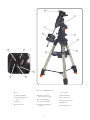 4
4
-
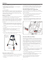 5
5
-
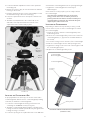 6
6
-
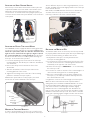 7
7
-
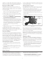 8
8
-
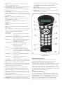 9
9
-
 10
10
-
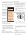 11
11
-
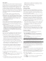 12
12
-
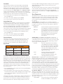 13
13
-
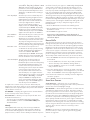 14
14
-
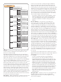 15
15
-
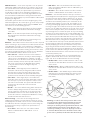 16
16
-
 17
17
-
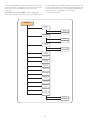 18
18
-
 19
19
-
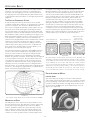 20
20
-
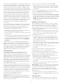 21
21
-
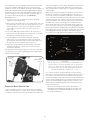 22
22
-
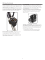 23
23
-
 24
24
-
 25
25
-
 26
26
-
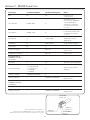 27
27
-
 28
28
-
 29
29
-
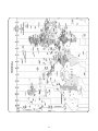 30
30
-
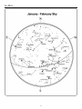 31
31
-
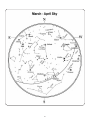 32
32
-
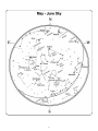 33
33
-
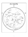 34
34
-
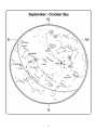 35
35
-
 36
36
-
 37
37
-
 38
38


Celestron CGEM DX Owner's manual
- Category
- Telescopes
- Type
- Owner's manual
- This manual is also suitable for
Ask a question and I''ll find the answer in the document
Finding information in a document is now easier with AI
Related papers
-
Celestron C8-NGT User manual
-
-
-
-
-
-
-
-
-
Celestron C5-S User manual
Other documents
-
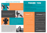 Crazefoto Car Phone Mount,CD Slot Car Phone Holder Universal Car Cradle Mount User manual
-
 EZPole EZL21B User manual
-
Orion Sirius EQ?G User manual
-
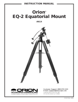 ORION TELESCOPES & BINOCULARS EQ-2 Equatorial Mount 9019 User manual
-
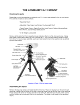 Explore Scientific LOSMANDY G-11 PMC-Eight GOTO Mount Owner's manual
-
iOptron #6002 Owner's manual
-
Bushnell 78-0040 User manual
-
Zhumell ECLIPSE 114 User manual
-
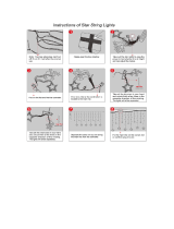 Twinkle Star 12 Stars 138 LED Curtain String Lights, Window Curtain Lights User manual
-


