Page is loading ...

Serial Number
Decal
Model No. PFTL99513.0
Serial No.
Write the serial number in the space
above for reference.
CAUTION
Read all precautions and instruc-
tions in this manual before using
this equipment. Save this manual
for future reference.
USER’S MANUAL
www.proform.com
ACTIVATE YOUR
WARRANTY
To register your product and
activate your warranty today,
go to www.proformservice.com/
registration.
CUSTOMER CARE
For service at any time, go to
www.proformservice.com.
Or call 1-888-533-1333
Mon.–Fri. 6 a.m.–6 p.m. MT
Sat. 8 a.m.–12 p.m. MT
Please do not contact the store.

2
This drawing shows the locations of the warning
decals. If a decal is missing or illegible, call
the telephone number on the front cover of
this manual and request a free replacement
decal. Apply the decal in the location shown.
Note: The decals may not be shown at actual size.
WARNING DECAL PLACEMENT
PROFORM is a registered trademark of ICON IP, Inc.
WARNING DECAL PLACEMENT . . . . . . . . . . . . . . . . . . . . . . . . . . . . . . . . . . . . . . . . . . . . . . . . . . . . . . . . . . . . . . .2
IMPORTANT PRECAUTIONS . . . . . . . . . . . . . . . . . . . . . . . . . . . . . . . . . . . . . . . . . . . . . . . . . . . . . . . . . . . . . . . . . .3
BEFORE YOU BEGIN. . . . . . . . . . . . . . . . . . . . . . . . . . . . . . . . . . . . . . . . . . . . . . . . . . . . . . . . . . . . . . . . . . . . . . . .7
PART IDENTIFICATION CHART. . . . . . . . . . . . . . . . . . . . . . . . . . . . . . . . . . . . . . . . . . . . . . . . . . . . . . . . . . . . . . . .8
ASSEMBLY . . . . . . . . . . . . . . . . . . . . . . . . . . . . . . . . . . . . . . . . . . . . . . . . . . . . . . . . . . . . . . . . . . . . . . . . . . . . . . . .9
OPERATION AND ADJUSTMENT . . . . . . . . . . . . . . . . . . . . . . . . . . . . . . . . . . . . . . . . . . . . . . . . . . . . . . . . . . . . .18
HOW TO FOLD AND MOVE THE TREADMILL . . . . . . . . . . . . . . . . . . . . . . . . . . . . . . . . . . . . . . . . . . . . . . . . . . .28
TROUBLESHOOTING . . . . . . . . . . . . . . . . . . . . . . . . . . . . . . . . . . . . . . . . . . . . . . . . . . . . . . . . . . . . . . . . . . . . . .29
EXERCISE GUIDELINES . . . . . . . . . . . . . . . . . . . . . . . . . . . . . . . . . . . . . . . . . . . . . . . . . . . . . . . . . . . . . . . . . . . .32
PART LIST. . . . . . . . . . . . . . . . . . . . . . . . . . . . . . . . . . . . . . . . . . . . . . . . . . . . . . . . . . . . . . . . . . . . . . . . . . . . . . . .34
EXPLODED DRAWING. . . . . . . . . . . . . . . . . . . . . . . . . . . . . . . . . . . . . . . . . . . . . . . . . . . . . . . . . . . . . . . . . . . . . .36
ORDERING REPLACEMENT PARTS. . . . . . . . . . . . . . . . . . . . . . . . . . . . . . . . . . . . . . . . . . . . . . . . . . . Back Cover
LIMITED WARRANTY. . . . . . . . . . . . . . . . . . . . . . . . . . . . . . . . . . . . . . . . . . . . . . . . . . . . . . . . . . . . . . . Back Cover
TABLE OF CONTENTS

3
1. It is the responsibility of the owner to ensure
that all users of this treadmill are adequately
informed of all warnings and precautions.
2. Before beginning any exercise program,
consult your physician. This is especially
important for persons over age 35 or persons
with pre-existing health problems.
3. Use the treadmill only as described in this
manual.
4. The treadmill is intended for home use only.
Do not use the treadmill in any commercial,
rental, or institutional setting.
5. Keep the treadmill indoors, away from mois-
ture and dust. Do not put the treadmill in a
garage or covered patio, or near water.
6. Place the treadmill on a level surface, with
at least 8 ft. (2.4 m) of clearance behind it
and 2 ft. (0.6 m) on each side. Do not place
the treadmill on any surface that blocks air
openings. To protect the floor or carpet from
damage, place a mat under the treadmill.
7. Do not operate the treadmill where aerosol
products are used or where oxygen is being
administered.
8. Keep children under age 12 and pets away
from the treadmill at all times.
9. The treadmill should be used only by per-
sons weighing 350 lbs. (159 kg) or less.
10. Never allow more than one person on the
treadmill at a time.
11. Wear appropriate exercise clothes while
using the treadmill. Do not wear loose
clothes that could become caught in the
treadmill. Athletic support clothes are recom-
mended for both men and women. Always
wear athletic shoes. Never use the treadmill
with bare feet, wearing only stockings, or in
sandals.
12. Plug the power cord into a surge suppressor
(not included), and plug the surge suppres-
sor into an appropriate outlet (see page 18).
To avoid overloading the circuit, do not plug
other electrical devices, except for low-power
devices such as cell phone chargers, into
the surge suppressor or into an outlet on the
same circuit.
13. Use only a surge suppressor that meets all of
the specifications described on page 18. To
purchase a surge suppressor, see your local
PROFORM dealer, call the telephone number
on the front cover of this manual, or see your
local electronics store.
14. Failure to use a properly functioning surge
suppressor could result in damage to the
control system of the treadmill. If the control
system is damaged, the walking belt may
slow, accelerate, or stop unexpectedly, which
may result in a fall and serious injury.
15. Keep the power cord and the surge suppres-
sor away from heated surfaces.
16. Never move the walking belt while the power
is turned off. Do not operate the treadmill
if the power cord or plug is damaged, or if
the treadmill is not working properly. (See
TROUBLESHOOTING on page 29 if the tread-
mill is not working properly.)
17. Read, understand, and test the emergency
stop procedure before using the treadmill
(see HOW TO TURN ON THE POWER on
page 20).
18. Never start the treadmill while you are stand-
ing on the walking belt. Always hold the
handrails while using the treadmill.
19. The treadmill is capable of high speeds.
Adjust the speed in small increments to
avoid sudden jumps in speed.
WARNING: To reduce the risk of burns, fire, electric shock, or injury to persons, read
all important precautions and instructions in this manual and all warnings on your treadmill before
using your treadmill. ICON assumes no responsibility for personal injury or property damage sus-
tained by or through the use of this product.
IMPORTANT PRECAUTIONS

4
20. The heart rate monitor is not a medical
device. Various factors, including the user’s
movement, may affect the accuracy of heart
rate readings. The heart rate monitor is
intended only as an exercise aid in determin-
ing heart rate trends in general.
21. Never leave the treadmill unattended while
it is running. Always remove the key, press
the power switch into the off position (see
the drawing on page 7 for the location of the
power switch), and unplug the power cord
when the treadmill is not in use.
22. Do not attempt to move the treadmill until it
is properly assembled. (See ASSEMBLY on
page 9, and HOW TO FOLD AND MOVE THE
TREADMILL on page 28.) You must be able
to safely lift 45 lbs. (20 kg) to raise, lower, or
move the treadmill.
23. When folding or moving the treadmill, make
sure that the storage latch is holding the
frame securely in the storage position.
24. Never insert any object into any opening on
the treadmill.
25. Inspect and properly tighten all parts of the
treadmill regularly.
26. DANGER: Always unplug the power
cord immediately after use, before clean-
ing the treadmill, and before performing the
maintenance and adjustment procedures
described in this manual. Never remove the
motor hood unless instructed to do so by an
authorized service representative. Servicing
other than the procedures in this manual
should be performed by an authorized ser-
vice representative only.
27. Over exercising may result in serious injury
or death. If you feel faint or if you experience
pain while exercising, stop immediately and
cool down.
SAVE THESE INSTRUCTIONS

5

6
all
STANDARD SERVICE PLANS

7
Thank you for selecting the revolutionary
PROFORM
®
Power 995i treadmill. The Power 995i
treadmill offers an impressive selection of features
designed to make your workouts at home more effec-
tive and enjoyable. And when you’re not exercising, the
unique treadmill can be folded up, requiring less than
half the fl oor space of other treadmills.
For your benefi t, read this manual carefully before
using the treadmill. If you have questions after
reading this manual, please see the front cover of this
manual. To help us assist you, please note the product
model number and serial number before contacting us.
The model number and the location of the serial num-
ber decal are shown on the front cover of this manual.
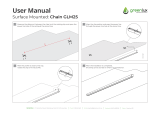
Before reading further, please review the drawing
below and familiarize yourself with the labeled parts.
BEFORE YOU BEGIN
Handrail
Upright
Tray
Key/Clip
Power Switch
Walking Belt
Platform Cushion
Foot Rail
Power Cord
Idler Roller
Adjustment Screws
Console
Heart Rate Monitor
Length: 6 ft. 6 in. (198 cm)
Width: 3 ft. (91 cm)

8
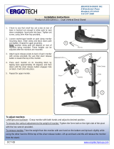
3/8" Star
Washer (13)–6
5/16" Nut (12)–2
5/16" Star
Washer (11)–10
#10 x 3/4" Screw
(9)–4
3/8" x 4" Screw (7)–6
#8 x 1/2" Silver
Screw (10)–1
#8 x 1/2"
Screw (1)–10
5/16" x 1 3/4"
Bolt (6)–1
5/16" x 2 1/4"
Bolt (3)–1
#10 Star
Washer (5)–4
5/16" x 2 1/2"
Screw (28)–4
Wheel Spacer
(63)–2
PART IDENTIFICATION CHART
Use the drawings below to identify small parts used for assembly. The number in parentheses below each draw-
ing is the key number of the part, from the PART LIST near the end of this manual. The number following the key
number is the quantity used for assembly. Note: If a part is not in the hardware kit, check to see if it is pre-
attached. Extra parts may be included.

9
• Assembly requires two persons.
• Place all parts in a cleared area and remove the
packing materials. Do not dispose of the packing
materials until you fi nish all assembly steps.
• After shipping, there may be an oily substance
on the exterior of the treadmill. This is normal. If
there is an oily substance on the treadmill, wipe
it off with a soft cloth and a mild, non-abrasive
cleaner.
• Left parts are marked “L” or “Left” and right parts
are marked “R” or “Right.”
• To identify small parts, see page 8.
• Assembly requires the following tools:
the included hex key
one adjustable wrench
one Phillips screwdriver
To avoid damaging parts, do not use power tools.
ASSEMBLY
1. Go to www.proformservice.com/
registration on your computer and register
your product.
• activates your warranty
• saves you time if you ever need to contact
Customer Care
• allows us to notify you of upgrades and offers
Note: If you do not have Internet access, call
Customer Care (see the front cover of this
manual) and register your product.
1

10
2. Make sure that the power cord is unplugged.
Press a Base Cap (74) into each side of the
Base (94).
Remove the tie securing the Upright Wire (81) to
the front of the Base (94).
Identify the Right Upright (90). Have a second
person hold the Right Upright near the Base
(94).
See the inset drawing. Tie the wire tie in the
Right Upright (90) securely around the end of the
Upright Wire (81). Then, insert the Upright Wire
into the lower end of the Right Upright as you
pull the other end of the wire tie out of the Right
Upright.
Then, remove and discard the indicated screw (A).
3. Lay the Right Upright (90) near the Base (94).
Press the Grommet (77) into the square hole in
the Right Upright. Make sure not to pinch the
ground wire.
Then, attach the ground wire to the Right Upright
(90) with a #8 x 1/2" Silver Screw (10) as shown.
94
94
90
90
81
10
90
Wire
Tie
Wire
Tie
2
81
77
Ground
Wire
Square
Hole
74
74
A
3

11
4. Insert a Wheel Spacer (63) into a Front Wheel
(62). Hold the Front Wheel inside the lower end
of the Right Upright (90), and insert a 3/8" x 4"
Screw (7) with a 3/8" Star Washer (13) into the
Right Upright and the Front Wheel.
Repeat this step on the other side of the
treadmill (not shown).
7
62
63
13
90
5. Place a piece of packing material (B) under
the right side of the Base (94). Hold the Right
Upright (90) against the Base. Make sure not
to pinch the Upright Wire (81).
Insert two 3/8" x 4" Screws (7) with two 3/8" Star
Washers (13) into the Right Upright (90), and
partially tighten the three Screws into the Base
(94); do not fully tighten the Screws yet.
Move the packing material (A) to the left side
of the Base (94) and attach the Left Upright
(not shown) in the same way. Note: There are
no wires on the left side.
Remove the packing material (B) from under-
neath the Base (94).
7
90
13
7
94
81
5
B
4

12
6. Identify the Left and Right Base Covers (82, 83).
Slide the Left Base Cover onto the Left Upright
(89), and slide the Right Base Cover onto the
Right Upright (90). Do not press the Base
Covers into place yet.
Identify the Right and Left Bottom Handrail
Covers (84, 85). Slide the Left Bottom Handrail
Cover onto the Left Upright (89), and slide the
Right Bottom Handrail Cover onto the Right
Upright (90).
82
85
90
83
84
89
7. Attach the Left Handrail (86) to the Left Upright
(89) with two 5/16" x 2 1/2" Screws (28) and two
5/16" Star Washers (11). Firmly tighten the
Screws.
Attach the Right Handrail (87) to the Right
Upright (90) in the same way.
Remove the wire tie from the Upright Wire (81).
90
7
87
86
89
81
11
28
11
28
Wire
Tie
6

13
8. If there are four screws (C) in the locations
shown, remove and discard them.
9. Set the console assembly face down on a soft
surface to avoid scratching the console assem-
bly. Remove and save the four 5/16" x 1/2"
Screws (4). They will be used in the next step.
8
9
C
4
C
4
Console
Assembly
10. Set the console assembly on the Left and Right
Handrails (86, 87). Make sure not to pinch any
wires (D, 81).
Attach the console assembly with the four 5/16"
x 1/2" Screws (4) that you removed in step 9 and
four 5/16" Star Washers (11). Do not tighten the
Screws yet.
10
Console
Assembly
87
86
4
11
4
11
81
D

14
11. Attach the console assembly to the Handrails
(86, 87) with four #10 x 3/4" Screws (9) and four
#10 Star Washers (5) as shown. Start all four
Screws, and then tighten them.
5
11
5
9
86
87
9
Console
Assembly
12. Connect the Upright Wire (81) to the console
wire (D). See the inset drawing. The connec-
tors should slide together easily and snap
into place. If they do not, turn one connector
and try again. IF YOU DO NOT CONNECT THE
CONNECTORS PROPERLY, THE CONSOLE
MAY BECOME DAMAGED WHEN YOU TURN
ON THE POWER.
Insert the excess wires (D, 81) into the Right
Upright (90).
Firmly tighten the four 5/16" x 1/2" Screws (4)
(only two are shown).
81
81
D
12
4
90
D

15
13. Attach the Right Handrail Cover (92) to the Right
Handrail (87) with three #8 x 1/2" Screws (1). Do
not overtighten the Screws.
Attach the Left Handrail Cover (79) to the Left
Handrail (86) in the same way.
92
79
86
1
87
1
13
14. Slide the Left Bottom Handrail Cover (85)
up against the Left Handrail Cover (79), and
attach the Left Bottom Handrail Cover with two
#8 x 1/2" Screws (1). Do not overtighten the
Screws.
Attach the Right Bottom Handrail Cover (84)
in the same way.
14
79
1
84
85
1

16
15. Note: If assembled on a smooth surface, the
treadmill may roll forward during this step.
Raise the Frame (56) to the upright position.
IMPORTANT: Do not raise the Frame past the
vertical position. Have a second person hold
the Frame until step 17 is completed.
Orient the Latch Crossbar (38) as shown. Make
sure that the “This side toward belt” sticker
(E) is facing the treadmill. Attach the Latch
Crossbar to the brackets on the Frame (56) with
two 5/16" x 3/4" Screws (25) and two 5/16" Star
Washers (11).
56
38
E
11
11
25
25
Brackets
15
16. Orient the Storage Latch (53) so that the decals
are facing away from the treadmill as shown.
Attach the lower end of the Storage Latch (53) to
the bracket on the Base (94) with a 5/16" x 1 3/4"
Bolt (6) and a 5/16" Nut (12).
Raise the Storage Latch (53) to a vertical posi-
tion. If there is a tie in the top of the Storage
Latch, remove and discard it.
94
53
6
Decals
12
Tie
16

17
17. Attach the upper end of the Storage Latch (53)
to the bracket on the Latch Crossbar (38) with a
5/16" x 2 1/4" Bolt (3) and a 5/16" Nut (12).
Lower the Frame (56) (see HOW TO LOWER
THE TREADMILL FOR USE on page 28).
38
3
56
12
53
17
18. Firmly tighten the six 3/8" x 4" Screws (7) (only
one side is shown).
Press the Left Base Cover (82) and the Right
Base Cover (83) onto the Base (94).
18
83
82
94
7
19. Make sure that all parts are properly tightened before you use the treadmill. If there are sheets of plastic
on the treadmill decals, remove the plastic. To protect the fl oor or carpet, place a mat under the treadmill. To
avoid damage to the console, keep the treadmill out of direct sunlight. Keep the included hex keys in a secure
place; one of the hex keys is used to adjust the walking belt (see pages 30 and 31). Note: Extra parts may be
included.

18
OPERATION AND ADJUSTMENT
HOW TO CONNECT THE POWER CORD
Use a Surge Suppressor
Your treadmill, like other electronic equipment, can be
damaged by sudden voltage changes in your home’s
power. Voltage surges, spikes, and noise interfer-
ence can result from weather conditions or from other
appliances being turned on or off. To decrease the
risk of damaging the treadmill, always use a surge
suppressor with the treadmill. To purchase a surge
suppressor, see precaution 13 on page 3.
Use only a surge suppressor that is UL 1449 listed as a
transient voltage surge suppressor (TVSS). The surge
suppressor must have a UL suppressed voltage rating
of 400 volts or less and a minimum surge dissipation of
450 joules. The surge suppressor must also be electri-
cally rated for 120 volts AC and 15 amps. There must
be a monitoring light on the surge suppressor to indi-
cate whether it is functioning properly. Failure to use a
properly functioning surge suppressor could result
in damage to the control system of the treadmill
and serious injury to users.
Plug in the Power Cord
The treadmill must be grounded. If it should malfunc-
tion or break down, grounding provides a path of least
resistance for electric current to reduce the risk of elec-
tric shock. The treadmill power cord has a plug with a
grounding pin (see drawing 1 on this page).
Plug the power cord into a surge suppressor, and plug
the surge suppressor into an appropriate outlet that is
properly installed and grounded in accordance with all
local codes and ordinances. The outlet must be on a
nominal 120-volt circuit capable of carrying 15 or
more amps. To avoid overloading the circuit, do
not plug other electrical devices, except for low-
power devices such as cell phone chargers, into
the surge suppressor or into an outlet on the same
circuit. IMPORTANT: The treadmill is not compat-
ible with GFCI-equipped outlets and may not be
compatible with AFCI-equipped outlets.
A temporary
adapter may
be used to
connect the
surge sup-
pressor to
a 2-pole
receptacle
if a properly
grounded
outlet is not
available.
The lug or wire extending from the adapter must
be connected with a metal screw to a permanent
ground such as a properly grounded outlet box cover.
Some 2-pole receptacle outlet box covers are not
grounded. Before using an adapter, contact a quali-
fied electrician to determine whether the outlet box
cover is grounded. The temporary adapter should
be used only until a properly grounded outlet can
be installed by a qualified electrician.
DANGER: Improper connection
of the power cord increases the risk of elec-
tric shock. Do not modify the plug—if it will
not fit an outlet, have a proper outlet installed
by a qualified electrician. If you are unsure
whether the treadmill is properly grounded,
contact a qualified electrician.
1
Surge
Suppressor
Grounding Pin
Grounded Outlet
2
Adapter
2-pole Receptacle
Lug
Grounding Pin
Metal
Screw

19
FEATURES OF THE CONSOLE
The treadmill console offers an impressive array of
features designed to make your workouts more effec-
tive and enjoyable. When you use the manual mode,
you can change the speed and incline of the treadmill
with the touch of a button. As you exercise, the console
will display instant exercise feedback. You can even
measure your heart rate using the handgrip heart rate
monitor.
In addition, the console features a selection of onboard
workouts. Each workout automatically controls the
speed and incline of the treadmill as it guides you
through an effective exercise session.
The console also features an iFit mode that enables
the treadmill to communicate with your wireless
network. With the iFit mode, you can download per-
sonalized workouts, create your own workouts, track
your workout results, race against other iFit users, and
access many other features.
You can even listen to your favorite workout music or
audio books with the console’s sound system while you
exercise.
To turn on the power, see page 20. To use the man-
ual mode, see page 20. To use an onboard workout,
see page 22. To use a set-a-goal workout, see page
23. To use an iFit workout, see page 24. To use the
sound system, see page 25. To change console set-
tings, see page 25.
IMPORTANT: If there are sheets of plastic on the
console, remove the plastic. To prevent damage
to the walking platform, wear clean athletic shoes
while using the treadmill. The fi rst time you use
the treadmill, observe the alignment of the walking
belt, and center the walking belt if necessary (see
page 31).
CONSOLE DIAGRAM

20
HOW TO TURN ON THE POWER
IMPORTANT: If the treadmill has been exposed to
cold temperatures, allow it to warm to room tem-
perature before you turn on the power. If you do
not do this, you may damage the console displays
or other electrical components.
Plug in the power cord
(see page 18). Next, locate
the power switch on the
treadmill frame near the
power cord. Press the
power switch into the reset
position.
IMPORTANT: The console features a display demo
mode, designed to be used if the treadmill is dis-
played in a store. If the displays light as soon as
you plug in the power cord and press the power
switch into the reset position, the demo mode is
turned on. To turn off the demo mode, hold down
the Stop button for a few seconds. If the displays
remain lit, see HOW TO CHANGE CONSOLE
SETTINGS on page 25 to turn off the demo mode.
Next, stand on the
foot rails of the
treadmill. Find the
clip attached to the
key and slide the
clip onto the waist-
band of your clothes.
Then, insert the key
into the console.
After a moment, the
displays will light.
IMPORTANT: In an emergency, the key can be
pulled from the console, causing the walking belt
to slow to a stop. Test the clip by carefully taking
a few steps backward; if the key is not pulled from
the console, adjust the position of the clip.
HOW TO USE THE MANUAL MODE
1. Insert the key into the console.
See HOW TO TURN ON THE POWER at the left.
2. Select the manual mode.
Press the Manual button on the console. If you
are not connected to iFit, the manual mode will be
selected automatically.
3. Start the walking belt.
To start the walking belt, press the Start button, the
Speed increase button, or one of the numbered
Quick Speed buttons.
If you press the Start button or the Speed increase
button, the walking belt will begin to move at 1
mph. As you exercise, change the speed of the
walking belt as desired by pressing the Speed
increase and decrease buttons. Each time you
press one of the buttons, the speed setting will
change by 0.1 mph; if you hold down the button,
the speed setting will change in increments of 0.5
mph. Note: After you press the button, it may take
a moment for the walking belt to reach the selected
speed setting.
If you press one of the numbered Quick Speed
buttons, the walking belt will gradually change
speed until it reaches the selected speed setting.
To select a speed setting that includes a decimal—
such as 3.5 mph—press two numbered buttons in
succession. For example, to select a speed setting
of 3.5 mph, press the 3 button and then immedi-
ately press the 5 button. Note: This will not function
if the console is set to metric units.
To stop the walking belt, press the Stop button. The
time will begin to flash in the display. To restart the
walking belt, press the Start button or the Speed
increase button.
Reset
Key
Clip
/