Page is loading ...

Part No. 334702G
IMPORTANT
Installer:
Leave Ibstaila+lon Inskucttons
with the homeowner
Homeowner:
Keep Installation Instruckons
for
fhJre feferenCe
Save
lnstallatton Instructions for loca’
electrical Inspector’s use
Convertible
Compact
Washer

I
I_
I’
s
Before you start...
Check location where washer
will be used Proper installation for
operation
IS your responsibility
Make sure you have everything
necessary for correct operation
Untape and open washer Ild.
/
Remove packages from washer,
Do not remove combination hose
I
or release shipping straps at this
I
time. Close and retape lid.
Grounded electrical outlet
is required See ElectrIcal
Hot and cold single-spout water
faucet:
Must be accessible within
4 feet of back of washer and
provide 5-100 PSI water pressure,
Water Heater:
Set
dater ?a washer.
deilver 1
to
Protection from weather:
Do not
store sr operate washer below
32 F See Use and Care Guide for
fbriher :-formation
Sink or laundry tub: VJ :i-
minimum carry-away capac,-1 c’
7 gallons per minute to dra,’
washer Top of sink or iti9 irclst KIT
at least 27 inches high and no
i-:gher +har-I 48 Inches fror^, oo+torr
SEE RECESSED AREA
INSTRUCTIONS ON
BACK COVER.
Support: Floor must be S:K
enougn To support washer AE Jht
of
250 pounds.
\
Important: Observe all governing
codes and ordinances.
Level floor:
maxlmurr? f’vzr SIOc?
under entire washer
-irlck
Electrical
Tools needed for
installation:
requirements
120
volt, 60 Hz, AC only, 15 or 20 ampere
fused electrical supply is required.
(Time-delay fuse or circuit breaker is
recommended.) It is recommended that
a separate circuit serving only this
appliance be provided.
receptacle is not available, it is the
personal responsibility and
obligation of the customer to have
a properly grounded 3-prong wall
receptacle installed by a qualified
electrician.
3-prong grounding
type wall
receptacle
Electrical Shock Hazard
l
Check with a qualified electrician if You
are in doubt as to whether the appliance
is properly grounded. Do Not modify the
power supply cord plug - if it will not fit the
outlet, have a proper outlet installed by a
qualified electrician. Improper connection
of the equipment-grounding conductor
can resull in a risk of electrical shock.
l
Do Not use an extension cord with this
appliance. Such use may result in a fire,
electrical shock or other personal injury.
0 Do Not have a fuse in the neutral or
grounding circuit. This could result in a
risk of electrical shock.
3-prong
grounding
Parts supplied
for installation:
Remove parts from packages. Check
that all parts were included.
Po\wer
SUPPlY
cord
Grounding
prow
Recommended
grounding
method
Figure 1
Do Not, under any circumstances,
remove the power supply cord
grounding prong.
For your personal safety, this appliance
must be grounded, This appliance is
equipped with a power supply cord
having a 3-prong grounding plug. To
minimize possible shock hazard, the
cord must be plugged into a mating 3-
prong grounding type wall receptacle,
grounded in accordance with National
Electrical Code, ANSVNFPA 70-1987
(or to the latest) and local codes and
ordinances. See Figure 1. If a mating wall
1 literature
2 rear casters
package
1 hose clamp
2 front casters
1 faucet adapter kit
PANEL A

Now stikrt...
With washer in laundry area.
carton on the floor
to the right side of the
washer,
Stand in front of washer.
I Firmly grasp washer and
gently lay it right side down on
foam corners,
3
n
Slide front casters into slots at
front corners of washer,
Lightly tap casters with small
hammer until they lock in place.
4
Firmly push rear casters into
m holes at rear corners of
washer. Lightly tap casters with small
hammer until they lock in place.
Check front and rear casters again.
If casters are not locked in place,
they may fall out when washer is
moved or cause the washer to
vibrate during use.
Now stand the washer
back
UT>.
II
Read
card
Shipping strap
with key
6
Untape and open washer
I lid. Read vellow card. Place
hand on top of agitator when
removing shipping straps. Firmly jerk
then pull the three (3) shipping straps
completely out of the washer, one at
a time. Put straps close to your tools.
Remove yellow tape from the top
front corners.
7
Remove yellow card. Take
n
combination hose out
of basket,
Place hose clamp over
n
washer drain connector.
Push drain hose down over washer
drain connector, Use pliers to open
clamp and slide clamp up over
drain hose and connector. Release
clamp and check for good fit. DO
NOT KINK OR TWIST HOSES.
u
f!
D
Inlets are plastic. Do not strip
or crossthread.
9
n
Attach inlet hose to top
inlet valve opening. Tighten
coupling by hand. Use pliers to
make an additional two-thirds turn.
C.
lo-
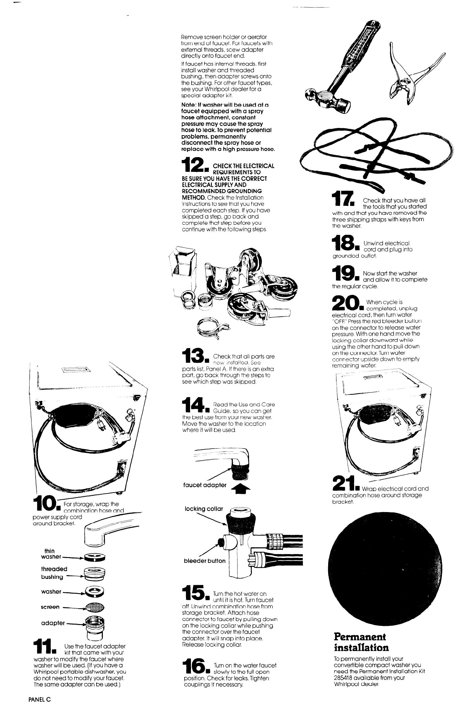
. For storage, wrap the
combinatic- L-- -hrl
power sup1 ’
-’
arouV hrr
thin
washer -+
GE3
11
n
Use the faucet adapter
kit that came with your
washer to modify the faucet where
washer will be used. (If you have a
Whirlpool portable dishwasher, you
do not need to modify your faucet.
The same adapter can be used.)
Remove screen holder or aerator
from end of faucet. For faucets with
external threads, stew adapter
directly onto faucet end.
If faucet has internal threads, first
install washer and threaded
bushing, then adapter screws onto
the bushing. For other faucet types,
see your Whirlpool dealer for a
special adapter kit.
Note: If washer will be used at a
faucet equipped with a spray
hose attachment, constant
pressure may cause the spray
hose to leak.To prevent potential
problems, permanently
disconnect the spray hose or
replace with a high pressure hose.
12
’
CHECK THE ELECTRICAL
REQUIREMENTS TO
BE SURE YOU HAVE THE CORRECT
ELECTRICAL SUPPLY AND
RECOMMENDED GROUNDING
METHOD. Check the Installation
Instructions to see that you have
completed each step. If you have
skipped a step, go back and
complete that step before you
continue with the following steps.
13
g
Check that all parts are
now nstalled. See
parts Irst, Panel A. If there is an extra
part, go back through the steps to
see which step was skipped.
14
Read the Use and Care
n
Guide, so you can get
the best use from your new washer.
Move the washer to the location
where it will be used.
faucet adapter
*
locking collar
m
n
Check that you have all
the tools that you started
with and that you have removed the
three shipping straps with keys from
the washer.
18
Unwind electrical
n
cord and plus into
grounded outlet. -
19
Now start the washer
n
and allow it to complete
the regular cycle.
20
When cycle is
n
completed, unplug
electrical cord, then turn water
“OFF.” Press the red bleeder button
on the connector to release water
pressure. With one hand move the
locking collar downward while
using the other hand to pull down
on the connector. Turn water
connector upside down to empty
remaining water.
4 Wrap electrical cord and
combination hose around storage
bracket.
15
n
Turn the hot water on
until it is hot. Turn faucet
‘off. Unwind combination hose from
storage bracket. Attach hose
connector to faucet by pulling down
on the locking collar while pushing
the connector over the faucet
adapter. It will snap into place.
Release locking collar.
16
Turn on the water faucet
n
slowly to the full open
position. Check for leaks. Tighten
couplings if necessary.
Permanent
installation
To permanently install your
convertible compact washer you
need the Permanent Installation Kit
285418 available from your
Whirlpool dealer.
PANEL C
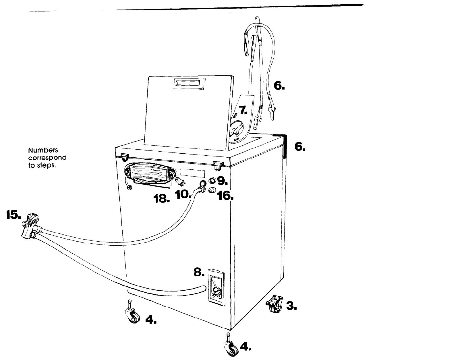
Numbers
correspond
to steps.
m
b
4
l
0
6.
3.

Recessed area
instructions.
This washer may be installed in
a recessed area or closet.
The installation spacing is in inches
and is the minimum allowable.
Additional spacing should be
considered for ease of installation
and servicing.
If closet door is installed, the
minimum air openings in top and
bottom are required. Louvered doors
with air openings in top and bottom
are acceptable.
Companion appliance spacing
should be considered.
This compact washer may be
installed with the compact dryer
companion appliance using
the Stack StandKit, Part No. 695570.
Only permanently installed units
may be used with Stack Kits,
Part Nos. 3390175 [White] or 3390196
(Almond).
Note: There are exhaust restrictions
on recess and closet installations for
dryers, Refer to dryer instructions for
proper installation,
Front view
(door not shown)
17” required for complete lid
opening - 9” minimum allowable.
Par-l No. 3347020 Prepared by Whirlpool Corporation, Benton Harbor, Michigan 49022
N Closet door
Closet door \
\
I
-14"
t
MAX.
48 Fi?
1
4
4"
t
242
1
II ;
I,
0
1
t
-I lb-l,::.
I’ l
A
3"
t
Side view
Minimum installation spacing.
Front view
Printed in U.S.A.
/