
CAUTION
Read all precautions and instruc-
tions in this manual before using
this equipment. Keep this manual
for future reference.
Model No. WLEL81914.0
Serial No.
Write the serial number in the space
above for reference.
USER’S MANUAL
www.weslo.com
Serial Number Decal
(under frame)
To register your product and
activate your warranty today,
go to www.wesloservice.com/
registration.
For service at any time, go to
www.wesloservice.com.
Or call 1-866-699-3756
Mon.–Fri. 6 a.m.–6 p.m. MT
Sat. 8 a.m.–12 p.m. MT
Please do not contact the store.
ACTIVATE YOUR
WARRANTY
CUSTOMER CARE

2
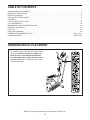
WARNING DECAL PLACEMENT
TABLE OF CONTENTS
WARNING DECAL PLACEMENT . . . . . . . . . . . . . . . . . . . . . . . . . . . . . . . . . . . . . . . . . . . . . . . . . . . . . . . . . . . . . . .2
IMPORTANT PRECAUTIONS . . . . . . . . . . . . . . . . . . . . . . . . . . . . . . . . . . . . . . . . . . . . . . . . . . . . . . . . . . . . . . . . . .3
BEFORE YOU BEGIN. . . . . . . . . . . . . . . . . . . . . . . . . . . . . . . . . . . . . . . . . . . . . . . . . . . . . . . . . . . . . . . . . . . . . . . .5
PART IDENTIFICATION CHART. . . . . . . . . . . . . . . . . . . . . . . . . . . . . . . . . . . . . . . . . . . . . . . . . . . . . . . . . . . . . . . .6
ASSEMBLY . . . . . . . . . . . . . . . . . . . . . . . . . . . . . . . . . . . . . . . . . . . . . . . . . . . . . . . . . . . . . . . . . . . . . . . . . . . . . . . .7
HOW TO USE THE ELLIPTICAL . . . . . . . . . . . . . . . . . . . . . . . . . . . . . . . . . . . . . . . . . . . . . . . . . . . . . . . . . . . . . .14
FCC INFORMATION . . . . . . . . . . . . . . . . . . . . . . . . . . . . . . . . . . . . . . . . . . . . . . . . . . . . . . . . . . . . . . . . . . . . . . . .18
MAINTENANCE AND TROUBLESHOOTING . . . . . . . . . . . . . . . . . . . . . . . . . . . . . . . . . . . . . . . . . . . . . . . . . . . .19
EXERCISE GUIDELINES . . . . . . . . . . . . . . . . . . . . . . . . . . . . . . . . . . . . . . . . . . . . . . . . . . . . . . . . . . . . . . . . . . . .21
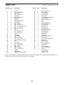
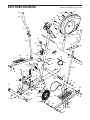
PART LIST. . . . . . . . . . . . . . . . . . . . . . . . . . . . . . . . . . . . . . . . . . . . . . . . . . . . . . . . . . . . . . . . . . . . . . . . . . . . . . . .22
EXPLODED DRAWING. . . . . . . . . . . . . . . . . . . . . . . . . . . . . . . . . . . . . . . . . . . . . . . . . . . . . . . . . . . . . . . . . . . . . .23
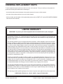
ORDERING REPLACEMENT PARTS . . . . . . . . . . . . . . . . . . . . . . . . . . . . . . . . . . . . . . . . . . . . . . . . . . Back Cover
LIMITED WARRANTY. . . . . . . . . . . . . . . . . . . . . . . . . . . . . . . . . . . . . . . . . . . . . . . . . . . . . . . . . . . . . . . Back Cover
This drawing shows the location(s) of the warning
decal(s). If a decal is missing or illegible, see
the front cover of this manual and request a
free replacement decal. Apply the decal in the
location shown. Note: The decal(s) may not be
shown at actual size.
WESLO is a registered trademark of ICON Health & Fitness, Inc.

3
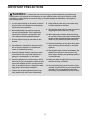
WARNING: To reduce the risk of serious injury, read all important precautions and
instructions in this manual and all warnings on your elliptical before using your elliptical. ICON
assumes no responsibility for personal injury or property damage sustained by or through the
use of this product.
1. It is the responsibility of the owner to ensure
that all users of the elliptical are adequately
informed of all precautions.
2. Before beginning any exercise program,
consult your physician. This is especially
important for persons over age 35 or per-
sons with pre-existing health problems.
3. Use the elliptical only as described in this
manual.
4. The elliptical is intended for home use only.
Do not use the elliptical in a commercial,
rental, or institutional setting.
5. Keep the elliptical indoors, away from mois-
ture and dust. Do not put the elliptical in a
garage or covered patio, or near water.
6. Place the elliptical on a level surface, with at
least 3 ft. (0.9 m) of clearance in the front and
rear of the elliptical and 2 ft. (0.6 m) on each
side. To protect the floor or carpet from dam-
age, place a mat under the elliptical.
7. Inspect and properly tighten all parts regu-
larly. Replace any worn parts immediately.
8. Keep children under age 12 and pets away
from the elliptical at all times.
9. The elliptical should not be used by persons
weighing more than 250 lbs. (113 kg).
10. Wear appropriate clothes while exercising;
do not wear loose clothes that could become
caught on the elliptical. Always wear athletic
shoes for foot protection while exercising.
11. Hold the handlebars or the upper body arms
when mounting, dismounting, or using the
elliptical.
12. The elliptical does not have a freewheel; the
pedals will continue to move until the fly-
wheel stops. Reduce your pedaling speed in
a controlled way.
13. Keep your back straight while using the ellip-
tical; do not arch your back.
14. Over exercising may result in serious injury
or death. If you feel faint, if you become short
of breath, or if you experience pain while
exercising, stop immediately and cool down.
IMPORTANT PRECAUTIONS

4
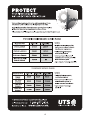
all
STANDARD SERVICE PLANS

5
BEFORE YOU BEGIN
Thank you for selecting the revolutionary WESLO
®
MOMENTUM G 3.4 elliptical. The MOMENTUM G 3.4
elliptical provides an impressive selection of features
designed to make your workouts at home more effec-
tive and enjoyable.
For your benefit, read this manual carefully before
you use the elliptical. If you have questions after
reading this manual, please see the front cover of this
manual. To help us assist you, note the product model
number and serial number before contacting us. The
model number and the location of the serial number
decal are shown on the front cover of this manual.
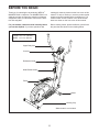
Before reading further, please familiarize yourself with
the parts that are labeled in the drawing below.
Leveling Cap
Upper Body Arm
Resistance Knob
Console
Pedal
Length: 3 ft. 7 in. (109 cm)
Width: 2 ft. 2 in. (66 cm)
Wheel
Water Bottle Holder*
*Water bottle is not included

6
M8 x 65mm
Carriage Bolt (57)–4
M8 x 55mm Bolt
(61)–2
M8 Locknut
(29)–2
M8 Acorn
Nut (59)–8
M8 Curved
Washer (14)–12
M5 x 10mm
Screw (2)–4
M5 x 20mm
Screw (12)–2
M5 x 14mm
Screw (35)–1
M8 Washer
(53)–4
M8 x 16mm
Screw (15)–4
M8 x 40mm Bolt
(60)–4
M8 x 20mm
Screw (28)–2
M8 Large
Washer (27)–2
M6 Washer
(62)–12
M6 Locknut
(39)–6
M17 Right Nut
(52)–1
M17 Left Nut
(47)–1
M6 x 35mm Bolt
(63)–6
PART IDENTIFICATION CHART
Use the drawings below to identify the small parts needed for assembly. The number in parentheses below each
drawing is the key number of the part, from the PART LIST near the end of this manual. The number following the
key number is the quantity needed for assembly. Note: If a part is not in the hardware kit, check to see if it
has been preassembled. Extra parts may be included.

7
• To hire an authorized service technician to
assemble this product, call 1-800-445-2480.
• Assembly requires two persons.
• Place all parts in a cleared area and remove the
packing materials. Do not dispose of the packing
materials until you fi nish assembly.
• Left parts are marked “L” or “Left” and right parts
are marked “R” or “Right.”
• To identify small parts, see page 6.
• In addition to the included tool(s), assembly
requires the following tools:
one Phillips screwdriver
one adjustable wrench
one pair of pliers
one rubber mallet
Assembly may be easier if you have a set of
wrenches. To avoid damaging parts, do not use
power tools.
ASSEMBLY
1. Go to www.wesloservice.com/registration on
your computer and register your product.
• activates your warranty
• saves you time if you ever need to contact
Customer Care
• allows us to notify you of upgrades and offers
Note: If you do not have Internet access, call
Customer Care (see the front cover of this
manual) and register your product.
1
2
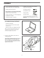
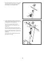
2. Identify the Rear Stabilizer (36), which has
Leveling Caps (37).
Attach the Rear Stabilizer (36) to the Frame (16)
with two M8 x 65mm Carriage Bolts (57), two
M8 Curved Washers (14), and two M8 Acorn
Nuts (59); start both Carriage Bolts, and then
tighten the Acorn Nuts.
36
37
37
14
14
59
59
57
16

8
3
4
38
57
14
59
16
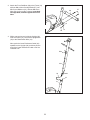
3. Attach the Front Stabilizer (38) to the Frame (16)
with two M8 x 65mm Carriage Bolts (57), two
M8 Curved Washers (14), and two M8 Acorn
Nuts (59) (only one side is shown); start both
Carriage Bolts, and then tighten the Acorn
Nuts.
4. While a second person holds the Upright (32)
near the Frame (16), connect the Upright Wire
(33) to the Reed Switch Wire (18).
Next, push the Lower Resistance Cable (24)
upward into the Upright (32), and then pull the
end of the Lower Resistance Cable out of the
indicated hole.
32
24
18
16
33
Hole

9
6
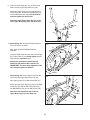
5. Insert the excess wire and cable into the
Frame (16).
Tip: Avoid pinching the wire and the cable.
Slide the Upright (32) onto the Frame (16).
Attach the Upright (32) with four M8 x 16mm
Screws (15) and four M8 Curved Washers (14);
start all the Screws, and then tighten them.
5
Avoid pinching
the wire and
the cable
32
15
15
15
14
14
15
16
Avoid pinching
the cable
24
32
35
34
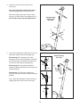
6. Connect the Resistance Cable (34) to the Lower
Resistance Cable (24) in the following way:
See drawing A. Pull upward on the metal
bracket (A) on the Lower Resistance Cable (24),
and insert the tip of the Resistance Cable (34)
into the wire clip inside the metal bracket.
See drawing B. Firmly pull the Resistance
Cable (34) upward and slide it into the top of the
metal bracket (A).
See drawing C. Using pliers, squeeze the
prongs on the upper end of the metal bracket (A)
together.
Then, attach the Resistance Control (34) to the
Upright (32) with an M5 x 14mm Screw (35).
A
B
C
24
34
34
A
A
A

10
7
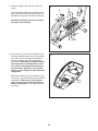
8. Using a plastic bag to keep your hands clean,
apply a generous amount of the included grease
to the right axle on the Upright (32).
Next, orient an Upper Body Leg (44) as
shown and slide it onto the right axle on the
Upright (32).
Attach the Upper Body Leg (44) with an M8 x
20mm Screw (28) and an M8 Large Washer (27).
Attach the other Upper Body Leg (44) in the
same way.
Then, press a Pivot Cap (26) firmly onto each
M8 x 20mm Screw (28).
Grease
8
7. Attach the Water Bottle Holder (9) to the Upright
(32) with two M5 x 20mm Screws (12); start
both Screws, and then tighten them.
9
12
32
32
27
28
26
44
44
28
26
27

11
9
60
59
14
41
44
44
44
65
44
41
10a
10b
29
46
53
53
61
51
51
52
55
3
47
46
Grease
9. Orient an Upper Body Arm (41) as shown and
slide it onto the right Upper Body Leg (44).
Attach the Upper Body Arm (41) with two M8 x
40mm Bolts (60), two M8 Curved Washers (14)
and two M8 Acorn Nuts (59); start both Bolts,
and then tighten the Acorn Nuts.
Attach the other Upper Body Arm (41) to the
other Upper Body Leg (44) in the same way.
10. See drawing 10a. Identify the Right Pedal Arm
(51) and orient it as shown.
Next, apply grease to the Right Pedal Arm
Axle (55).
Insert the Right Pedal Arm Axle (55) into the right
arm of the Crank (3), and firmly tighten the M17
Right Nut (52) clockwise onto it.
Repeat this procedure to attach the Left
Pedal Arm (46) with the M17 Left Nut (47).
IMPORTANT: You must firmly tighten the Left
Nut counterclockwise to attach it.
See drawing 10b. Insert a Spacer (65) into the
lower end of the right Upper Body Leg (44).
Next, apply grease to an M8 x 55mm Bolt (61).
Attach the right Upper Body Leg (44) to the Right
Pedal Arm (51) with the M8 x 55mm Bolt (61),
two M8 Washers (53), and an M8 Locknut (29).
Attach the Left Pedal Arm (46) to the left
Upper Body Leg (44) in the same way.
Grease

12
11
56
62
62
39
63
54
46
11. Identify the Right Pedal (56) and orient it as
shown.
Attach the Right Pedal (56) to the Right Pedal
Arm (51) with three M6 x 35mm Bolts (63), six
M6 Washers (62), and three M6 Locknuts (39).
Attach the Left Pedal (54) to the Left Pedal
Arm (46) in the same way.
12
12. The Console (1) can use two AA batteries (not
included); alkaline batteries are recommended.
Do not use old and new batteries together or
alkaline, standard, and rechargeable batter-
ies together. IMPORTANT: If the Console has
been exposed to cold temperatures, allow
it to warm to room temperature before you
insert batteries. Otherwise, you may dam-
age the console displays or other electronic
components.
Remove the battery cover from the back of the
Console (1), and insert batteries into the battery
compartment. Make sure to orient the bat-
teries as shown by the diagram inside the
battery compartment. Then, reattach the bat-
tery cover.
1
Battery
Cover
51

13
13
14. Make sure that all parts of the elliptical are properly tightened. Extra parts may be included. Place a mat
under the elliptical to protect the floor.
13. While a second person holds the Console (1)
near the Upright (32), connect the wire on the
Console to the Upright Wire (33).
Tip: Avoid pinching the wires. Attach the
Console (1) to the Upright (32) with four M5 x
10mm Screws (2); start all the Screws, and
then tighten them.
Avoid pinching
the wires
1
33
32
2

14
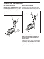
HOW TO MOVE THE ELLIPTICAL
Due to the size and weight of the elliptical, moving
it requires two persons. Stand in front of the ellipti-
cal, hold the upright, and place one foot against one of
the front stabilizer caps. Pull on the upright and have a
second person lift the rear stabilizer until the elliptical
will roll on the front stabilizer caps. Carefully move the
elliptical to the desired location, and then lower it to the
floor.
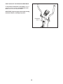
HOW TO USE THE ELLIPTICAL
To m o unt the e llip tica l in the elli p tica l mo d e, h old the
upper body arms and step onto the pedal that is in the
lower position. Then, step onto the other pedal.
Push the pedals until they begin to move with a con-
tinuous motion. Note: The pedals can turn in either
direction. It is recommended that you move the
pedals in the direction shown by the arrow; how-
ever, for variety, you can turn the pedals in the
opposite direction.
To d i smou nt t h e el lipt i cal , wai t un t il t he p e dal s com e to
a complete stop. Note: The elliptical does not have
a free wheel; the pedals will continue to move until
the flywheel stops. When the pedals are stationary,
step off the higher pedal first. Then, step off the lower
pedal.
HOW TO USE THE ELLIPTICAL
Pull here
Lift here
Place
your foot
here
Pedals
Upper Body Arms

15
HOW TO ADJUST THE PEDALING RESISTANCE
To increase the resistance of the pedals, turn the
resistance knob clockwise; to decrease the resis-
tance, turn the knob counterclockwise.
IMPORTANT: Stop turning the knob when turning
becomes difficult, or damage may result.
Resistance
Knob

16
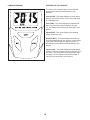
CONSOLE DIAGRAM FEATURES OF THE CONSOLE
The easy-to-use console features five modes that
provide instant exercise feedback during your
workouts.
Scan (SCAN)—This mode displays the time, speed,
distance, and calorie modes, for a few seconds each,
in a repeating cycle.
Time (TMR)—This mode displays the elapsed time.
Note: If you set a time goal (see step 2 on page
17), this display will show the time remaining in your
workout.
Speed (SPD)—This mode displays your pedaling
speed, in miles per hour.
Distance (DST)—This mode displays the distance
you have pedaled during your workout, in miles. Note:
If you set a distance goal (see step 2 on page 17),
this display will show the distance remaining in your
workout.
Calorie (CAL)—This mode displays the approximate
number of calories you have burned during your work-
out. Note: If you set a calorie-burning goal (see step
2 on page 17), this display will show the number of
calories yet to be burned in your workout.

17
HOW TO USE THE CONSOLE
Make sure that batteries (not included) are installed in
the console (see assembly step 12 on page 12). If
there is a sheet of plastic on the console, remove the
plastic.
1. Turn on the console.
To t u rn o n th e con sole , pr e ss a ny b u tton on t he
console or simply begin pedaling.
2. Set a workout goal if desired.
To s e t a time , dis tanc e , o r cal orie - burn ing g oal for
your workout, press the MODE button repeatedly
until the word TMR, DST, or CAL, appears in the
display. Make sure that the word SCAN does not
appear in the display.
Next, press the SET button repeatedly to set a
goal. To set a goal quickly, hold down the SET but-
ton. To reset the goal, press the RESET button.
3. Begin pedaling and follow your progress with
the displays.
Scan mode—To select the scan mode, press the
MODE button repeatedly until the word SCAN
appears in the display.
Time, speed, distance, or calorie mode—To
select one of these modes for continuous display,
press the MODE button repeatedly until the name
of the desired mode appears in the display. Make
sure that the word SCAN does not appear in the
display.
As you exercise, the console will provide instant
feedback about your workout.
4. When you are finished exercising, the console
will turn off automatically.
If the pedals do not move for a few seconds, the
console will pause.
The console has an auto-off feature. If the ped-
als do not move and the console buttons are not
pressed for a few minutes, the power will turn off
automatically to save the batteries.

18
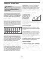
FCC INFORMATION
This equipment has been tested and found to comply with the limits for a Class B digital device, pursuant to part
15 of the FCC Rules. These limits are designed to provide reasonable protection against harmful interference
in a residential installation. This equipment generates, uses, and can radiate radio frequency energy and, if not
installed and used in accordance with the instructions, may cause harmful interference to radio communications.
However, there is no guarantee that interference will not occur in a particular installation. If this equipment does
cause harmful interference to radio or television reception, which can be determined by turning the equipment off
and on, try to correct the interference by one or more of the following measures:
• Reorient or relocate the receiving antenna.
• Increase the separation between the equipment and the receiver.
• Connect the equipment into an outlet on a circuit different from that to which the receiver is connected.
• Consult the dealer or an experienced radio/TV technician for help.
FCC CAUTION: To assure continued compliance, use only shielded interface cables when connecting to
computer or peripheral devices. Changes or modifications not expressly approved by the party respon-
sible for compliance could void the user’s authority to operate this equipment.

19
MAINTENANCE
Inspect and tighten all parts of the elliptical regularly.
Replace any worn parts immediately.
To c l ean the e llip tica l , u s e a damp clot h an d a s mall
amount of mild soap. IMPORTANT: To avoid damage
to the console, keep liquids away from the console
and keep the console out of direct sunlight.
CONSOLE TROUBLESHOOTING
Most console problems are the result of low batteries.
See assembly step 12 on page 12 for replacement
instructions.
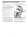
HOW TO ADJUST THE REED SWITCH
If the console does not display correct feedback, the
reed switch should be adjusted.
To a d just the reed swi t ch, firs t tu r n th e re s ist a nce knob
to the lowest setting.
Next, see assembly step 10 on page 11 and
remove the Left Pedal Arm (46) from the left Upper
Body Leg (44) and the left side of the Crank (3).
Then, see the EXPLODED DRAWING on page 23.
Remove the M4 x 50mm Screws (22) and the M5 x
16mm Screws (23) from the Left and Right Shields
(20, 21); note which size of Screw you remove from
each hole. Then, gently remove the Left Shield.
Locate the Reed Switch (18). Turn the Crank (3) until a
Magnet (8) is aligned with the Reed Switch.
Next, loosen, but do not remove, the two M4 x 10mm
Screws (17). Slide the Reed Switch (18) slightly closer
to or away from the Magnet (8). Then, retighten the two
Screws. Turn the Crank (3) for a moment.
Repeat these actions until the console displays correct
feedback. When the reed switch is correctly adjusted,
reattach the left shield and the left pedal arm.
MAINTENANCE AND TROUBLESHOOTING
8
18
3
17

20
HOW TO ADJUST THE DRIVE BELT
If you can feel the pedals slip while you are pedaling,
even when the resistance is at the highest level, the
drive belt may need to be adjusted.
To adjust the drive belt, first see assembly step 10 on
page 11 and remove the Right Pedal Arm (51) from
the right Upper Body Leg (44) and the right side of the
Crank (3).
Next, see the EXPLODED DRAWING on page 23.
Remove the M4 x 50mm Screws (22) and the M5 x
16mm Screws (23) from the Left and Right Shields
(20, 21); note which size of Screw you remove from
each hole. Then, gently remove the Right Shield.
Loosen the two M8 Locknuts (29) on the two M8 x
16mm Bolts (30). Then, tighten the M10 x 35mm Screw
(31) until the Drive Belt (5) is tight. When the Drive Belt
is tight, tighten the two Locknuts.
Then, reattach the right shield and the right pedal arm.
31
30
29
5
Page is loading ...
Page is loading ...
Page is loading ...
Page is loading ...
-
 1
1
-
 2
2
-
 3
3
-
 4
4
-
 5
5
-
 6
6
-
 7
7
-
 8
8
-
 9
9
-
 10
10
-
 11
11
-
 12
12
-
 13
13
-
 14
14
-
 15
15
-
 16
16
-
 17
17
-
 18
18
-
 19
19
-
 20
20
-
 21
21
-
 22
22
-
 23
23
-
 24
24


Weslo momentum G 3.4 User manual
- Type
- User manual
- This manual is also suitable for
Ask a question and I''ll find the answer in the document
Finding information in a document is now easier with AI
Related papers
Other documents
-
NordicTrack Elite 10.7 Elliptical User manual
-
AeroWorks EDGE 540 Assembly Manual
-
-
-
-
-
-
Pro-Form PRO 9.9 User manual
-
Pro-Form XP THINLINE 480 User manual
-
ProForm PFEL59915 Owner's manual