
TINSEA471JBRZ 49-7548 05-06 JR
Air Conditioners
Safety Instructions . . . . . . . . . . .2
Operating Instructions
Air Direction . . . . . . . . . . . . . . . .4
Auxiliary Controls . . . . . . . . . .5–9
Controls . . . . . . . . . . . . . . . . . . . .3
To Remove the Room Cabinet . .4
Vent Control . . . . . . . . . . . . . . . .4
Care and Cleaning
Air Filters . . . . . . . . . . . . . . . . . .11
Base Pan . . . . . . . . . . . . . . . . . .10
Outdoor Coils . . . . . . . . . . . . . .10
Room Cabinet and Case . . . . . .10
Vent Filter . . . . . . . . . . . . . . . . .10
Installation Instructions
Electrical Supply . . . . . . . . .14–17
Installing the Zoneline . . . .18, 19
Optional Drain Kit . . . . . . . . . .20
Preparation . . . . . . . . . . . . . . . .12
Replacing an Existing Unit? . . .13
Troubleshooting Tips . . . .21, 22
Normal Operating Sounds . . . .23
Consumer Support
Consumer Support . . .Back Cover
Product Registration . . . . . .25, 26
Warranty . . . . . . . . . . . . . . . . . .27
Heat/Cool Model 2800
Heat Pump Model 3800
Owner’s Manual and
Installation Instructions
ge.com
Write the model and serial
numbers here:
Model # ____________________
Serial # ____________________
Find these numbers on a label
behind the room cabinet on the
base pan.
Zoneline
®
Español
For a Spanish version of this
manual, visit our Website at
ge.com.
Para consultar una version en
español de este manual de
instrucciones, visite nuestro
sitio de internet ge.com.
Française
For a French version of this
manual, visit our Website at
www.electromenagersge.ca.
Pour une version française de
ce manuel d'utilisation, veuillez
visiter notre site web à l’adresse
www.electromenagersge.ca.

Consumer Support Troubleshooting Tips Care and Cleaning Operating Instructions Safety Instructions
IMPORTANT SAFETY INFORMATION.
READ ALL INSTRUCTIONS BEFORE USING.
WARNING!
For your safety, the information in this manual must be followed to minimize the risk of fire or
explosion, electric shock, or to prevent property damage, personal injury, or loss of life.
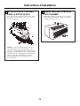
■ This Zoneline must be properly
installed in accordance with the
Installation Instructions before it is
used. See the Installation Instructions
in the back of this manual.
■ Replace immediately all electric service
cords that have become frayed or
otherwise damaged. A damaged power
supply cord must be replaced with a
new power supply cord obtained from
the manufacturer and not repaired.
Do not use a cord that shows cracks
or abrasion damage along its length
or at either the plug or connector end.
■ Unplug or disconnect the Zoneline at
the fuse box or circuit breaker before
making any repairs.
NOTE: We strongly recommend that any
servicing be performed by a qualified
individual.
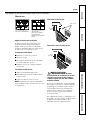
Replacing an existing unit?
For details, see the Installation
Instructions in this manual.
SAFETY PRECAUTIONS
READ AND FOLLOW THIS SAFETY INFORMATION CAREFULLY.
SAVE THESE INSTRUCTIONS
2

Quick Heat Recovery
Activates each time the thermostat is
switched from STOP or a COOL mode to a HEAT
mode. Electric heaters are energized until the
thermostat set point is reached. On heat pump
models, the heat pump operation will resume
at the next call for heat.
Safety Instructions Operating Instructions Care and Cleaning Troubleshooting Tips Consumer Support
3
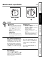
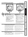
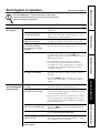
Controls
Temp Control
The temp control is used to maintain the
room temperature. The compressor will
cycle on and off to keep the room at the
same comfort level. When you turn the
knob to COOLER (blue), the indoor air
will become cooler. Turn the knob to
WARMER (red) and the indoor air will
become warmer.
3800 Series only
When the outdoor temperature is lower
than 20°F, heat is provided by the electric
heater in the air conditioner instead of by
the heat pump.
Mode Control
HIGH COOL and LOW COOL provide cooling
with different fan speeds.
HIGH HEAT and LOW HEAT provide heating
with different fan speeds.
LOW FAN or HIGH FAN provides air
circulation and filtering without cooling
or heating.
NOTE: If you move the switch from a cool or heat
setting to STOP or to a fan setting, the unit has an
automatic 3-minute delay before allowing the
compressor to restart in the cool or heat mode.
TEMP CONTROL MODE CONTROL
About the controls on your Zoneline. ge.com
About Your Heat Pump (3800 Series only)
Heat pumps can save money by removing heat
from the outside air—even when the outside
temperature is below freezing—and releasing
that heat indoors.
To get the best performance from your heat
pump, don’t change the room thermostat very
often. Raising the heat setting 2–3 degrees will
cause the Zoneline to use its electric heating
elements in order to reach the new temperature
setting quickly.
There is a three minute minimum compressor
run time at any setting to prevent short cycling.
The indoor fan motor starts before the
compressor and stops after the compressor
cycles off.
The electric heating elements use much
more electricity than heat pumps and cost
more to operate.

Consumer Support Troubleshooting Tips Care and Cleaning Operating Instructions Safety Instructions
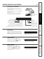
Ventilation Control
The ventilation control lever is located at the
upper left side of the Zoneline unit, behind
the room cabinet.
When set at the closed position, only the air
inside the room is circulated and filtered.
When set at the open position, some outdoor
air will be drawn into the room. This will
reduce the heating or cooling efficiency.
Energy Tip: Keep the vent control at the closed
position. The room air will be filtered and
circulated.
NOTE: Two shipping screws must be removed from the
vent door before use. See the Installation Instructions
in the back of this manual.
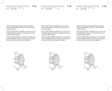
Air Direction
To adjust the air direction, remove the room
cabinet. Remove the 7 louver screws that hold
the louver insert in place. Flip the louver insert
180°, replace the screws and the room cabinet.
Remove the room cabinet and flip the louver
insert to change the air direction.
4
Other features of your Zoneline.
To Remove the Room Cabinet
Additional controls are located behind the
room cabinet.
To remove: Pull out at the bottom to release it
from the tabs (1). Then lift up (2).
To replace: Place the tabs over the top rail (1).
Push inward at the bottom until it snaps into
place (2).
Vent
control
(shown in
middle
position)
Open
position
Closed
position
Louver screws
Louver screws

5
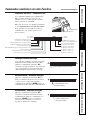
Auxiliary Controls on your Zoneline. ge.com
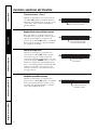
Auxiliary Controls—Dip Switches
The auxiliary dip switch controls are located
behind the room cabinet, through an opening
in the control panel.
Remove the room cabinet. See the To Remove the
Room Cabinet section.
The owner is responsible for checking switches
and ensuring they are in the desired position.
HIGH
COOL
1 2 3 4 5 6 1 2 3 4 5 67 8
UP
DOWN
UP
DOWN
ALLI
2
R (All Electric Heat)
(3800 Series models only)
C: FAN CN (Cooling–Smart Fan)
H: FAN CY (Heating–Smart Fan)
CLASS 2 (Remote Thermostat)
LOAD SHEDDING (CDC)
FREEZ Sen (Freeze Sentinel)
CONST FAN (Constant ON Fan)
No Function (Reserved for future use)
TL1 (H) (Temp. Limit 1–Heat)
TL2 (H) (Temp. Limit 2–Heat)
TL3 (H) (Temp. Limit 3–Heat)
TL1 (C) (Temp. Limit 1–Cool)
TL2 (C) (Temp. Limit 2–Cool)
TL3 (C) (Temp. Limit 3–Cool)
7 8
Heat Sentinel
HEAT BOOST
(3800 Series models only)
Safety Instructions Operating Instructions Care and Cleaning Troubleshooting Tips Consumer Support
All Electric Heat
This electric heat option functions only on the
3800 Series models. When this switch is enabled
(UP), heat pump operation is locked out, causing
the unit to provide only electric resistance heat.
Cooling—Smart Fan
When this switch is enabled (UP), it allows the
indoor fan to cycle on/off with the compressor.
When this switch is disabled (DOWN), it allows
the indoor fan to run continuously.
Heating—Smart Fan
When this switch is enabled (UP), it allows the
indoor fan to run continuously. When this
switch is disabled (DOWN), it allows the indoor
fan to cycle on/off with the heat pump or
heater operation.
ALLI
2
R (All Electric Heat)
C: FAN CN (Cooling–Smart Fan)
H: FAN CY (Heating–Smart Fan)
Dip Switches
Access Cover

6
Auxiliary controls on your Zoneline.
Remote Thermostat—Class 2
When this switch is enabled (UP), it allows the
unit to operate with a Class 2 Remote Control
Wall Thermostat. The unit controls are disabled.
Load Shedding (Central Desk Control)
This feature is active only if the unit is in
CDC mode. When this switch is enabled (UP),
the indoor fan can be turned ON or OFF with
the unit controls.
Freeze Sentinel
When this switch is enabled (UP), it turns OFF
the freeze sentinel protection feature. With the
switch disabled (DOWN), the freeze sentinel is
activated, which automatically provides heat
without user interface. This helps to prevent
plumbing damage by turning the heater and
indoor fan ON at 41°F and OFF at 46°F.
Constant ON Fan
When this switch is enabled (UP), it allows the
indoor fan to run continuously, at high speed,
even if the unit is in the STOP position.
Consumer Support Troubleshooting Tips Care and Cleaning Operating Instructions Safety Instructions
CLASS 2 (Remote Thermostat)
LOAD SHEDDING (CDC)
FREEZE Sen (Freeze Sentinel)
CONST FAN (Constant
ON Fan)

7
ge.com
Temperature Limiting
Temperature limiting can reduce energy costs
by limiting the lowest temperature that can be
set for cooling and the highest temperature that
can be set for heating. Temperature limiting is
controlled by the second six auxiliary switches.
The first three switches are used to select the
cooling limits, and the remaining three switches
are used to control the heating limits. This
feature is not available with the Remote
Thermostat—Class 2.
HIGH
COOL
1 2 3 4 5 6 1 2 3 4 5 67 8
UP
DOWN
UP
DOWN
TL1 (C) (Temp. Limit 1–Cool)
TL2 (C) (Temp. Limit 2–Cool)
TL3 (C) (Temp. Limit 3–Cool)
7 8
HIGH
COOL
1 2 3 4 5 6 1 2 3 4 5 67 8
UP
DOWN
UP
DOWN
TL1 (H) (Temp. Limit 1–Heat)
TL2 (H) (Temp. Limit 2–Heat)
TL3 (H) (Temp. Limit 3–Heat)
7 8
Temperature limiting during COOL mode
(all temperatures shown in °F)
UP DOWN Minimum Maximum
NONE 1, 2, 3 60° 85°
1 2, 3 64° 85°
1, 2 3 66° 85°
2 1, 3 68° 85°
2, 3 1 70° 85°
1, 2, 3 NONE 72° 85°
1, 3 2 74° 85°
3 1, 2 76° 85°
Temperature limiting during HEAT mode
(all temperatures shown in °F)
UP DOWN Minimum Maximum
NONE 4, 5, 6 60° 85°
4 5, 6 60° 80°
4, 5 6 60° 78°
5 4, 6 60° 76°
5, 6 4 60° 74°
4, 5, 6 NONE 60° 72°
4, 6 5 60° 70°
6 4, 5 60° 65°
Safety Instructions Operating Instructions Care and Cleaning Troubleshooting Tips Consumer Support
Heat Sentinel
When this switch is enabled (UP), it turns ON
the heat sentinel protection feature. With the
switch disabled (DOWN), the heat sentinel is
de-activated. This feature automatically provides
cooling without user interface. This helps to
prevent an excessively hot room by turning the
air conditioner ON at 85°F and OFF at 80°F.
Heat Sentinel
Heat Boost (AZ3800 only)
When this switch is enabled (UP) and outdoor
temperatures are between 20°F and 46°F, heat
pump only operation is locked out. This setting is
used to provide supplementary heat to the heat
pump operation in conditions where the heat
pump only operation is not sufficient to maintain
a consistent, comfortable room temperature.
NOTE: This is an auxiliary switch for AZ2800 models and
must remain in the (DOWN) position.
BOOST (Heat Boost Operation)

8
Consumer Support Troubleshooting Tips Care and Cleaning Operating Instructions Safety Instructions
Auxiliary controls on your Zoneline.
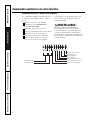
Auxiliary Controls—Terminal Connections
The auxiliary controls are located behind the
room cabinet beneath the access cover.
Remove the room cabinet. See the
To Remove the Room Cabinet section.
Remove the screw from the access cover.
To make wiring connections, insert the wires
into the bottom of the terminals and tighten
screws securely.
After all desired connections have been
made, replace the access cover and room
cabinet.
The owner is responsible for making all
connections and setting the appropriate
dip switches.
CAUTION:
Improper wiring may damage the Zoneline
electronics. No common busing is permitted.
Damage or erratic operation may result.
A separate wire pair must be run from each
separate controlling switch to each individual
Zoneline.
4
3
2
1
External Fan
Central Desk Control
Common - Ground
White - Heater
Yellow - Compressor
Black - Solenoid
Green - High Speed Fan
Green - Low Speed Fan
Red - 24 V AC only

9
Safety Instructions Operating Instructions Care and Cleaning Troubleshooting Tips Consumer Support
ge.com
External Fan (Obtained locally)
When connected, an auxiliary or external fan
can be controlled with the indoor fan motor
on the Zoneline. Connections provide 24 V AC
to energize a remote relay, turning on the
external fan.
External Fan
Central Desk Control
When connected, the unit can be turned ON
or OFF with a switch located at the Central
Control Panel. A separate wire pair must be
run from each separate controlling switch to
each individual Zoneline.
Central Desk Control
Remote Thermostat
When connected, the unit will be controlled
by a remote thermostat.
NOTE: The number 4 dip switch must be in the
enabled (UP) position to activate the remote
thermostat. (See the installation instructions
supplied with the remote thermostat).
IMPORTANT:
The Zoneline thermostat connections
provide 24 V AC only.
If using a digital/electronic wall thermostat,
you must set it to the 24 V AC setting.
See the Installation Instructions for the
wall thermostat.
CAUTION:
Damage to a wall thermostat or to the
Zoneline electronics can result from improper
connections. Special care must be used in
connecting the wires. No line voltage
connections should be made to any circuit.
Isolate all wires in building from line voltage.
Common - Ground
White - Heater
Yellow - Compressor
Black - Solenoid
Green - High Speed Fan
Green - Low Speed Fan
Red - 24 V AC only

Consumer Support Troubleshooting Tips Care and Cleaning Operating Instructions Safety Instructions
10
Care and cleaning.
Base Pan
In some installations, dirt or other debris may be
blown into the unit from the outside and settle in
the base pan (the bottom of the unit).
In some areas of the United States, a “gel-like” or
“slime-like” substance may be seen in the base pan.
Check it periodically and clean, if necessary.
Ventilation Filter
If the vent door is open, clean the vent filter twice a year
or as required.
Turn the Zoneline off before cleaning.
To remove the vent filter:
■ Remove the room cabinet. See the To Remove
the Room Cabinet section.
■ Remove the four screws securing the unit
flanges to the case.
■ Slide the unit from the wall case.
■ Grasp the vent filter tab and pull the filter out
by sliding it to the right.
To clean the vent filter:
■ Run water through the filter from the
back side.
■ Dry thoroughly before replacing.
Outdoor Coils
The coils on the outdoor side of the Zoneline
should be checked regularly. If they are clogged
with dirt or soot, they may be professionally
steam cleaned, a service available through your
GE service outlet. You will need to remove the
unit to inspect the coils because the dirt
buildup occurs on the inside.
Clean the outside coils regularly.
Room Cabinet and Case
Turn the Zoneline off and disconnect the
power supply.
To clean, use water and a mild detergent.
Do not use bleach or abrasives. Some commercial
cleaners may damage the plastic parts.
Coils
Grille

Safety Instructions Operating Instructions Care and Cleaning Troubleshooting Tips Consumer Support
11
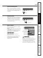
To maintain optimum performance, clean the filters at least every 30 days.
Air Filters
Turn the Zoneline off before cleaning.
The most important thing you can do to
maintain the Zoneline is to clean the filter
at least every 30 days. Clogged filters reduce
cooling, heating and air flow.
Keeping these filters clean will:
■ Decrease cost of operation.
■ Save energy.
■ Prevent clogged heat exchanger coils.
■ Reduce the risk of premature component
failure.
To clean the air filters:
■ Vacuum off the heavy soil.
■ Run water through the filters from the
back side.
■ Dry thoroughly before replacing.
NOTE: The air filters are interchangeable
and will fit in either the right or left side.
To remove the air filters:
To replace the air filters:
CAUTION: Do not operate the
Zoneline without the filters in place. If a filter
becomes torn or damaged, it should be replaced
immediately.
Operating without the filters in place or with
damaged filters will allow dirt and dust to reach
the indoor coil and reduce the cooling, heating,
airflow and efficiency of the unit.
Replacement filters are available from your
salesperson, GE dealer, GE Service and Parts
Center or authorized Customer Care
®
servicers.
Dirty filter—Needs cleaning Clogged filter—Greatly
reduces cooling, heating
and airflow.
FRONT
FRONT
Pull up
Push down
2 Air filters
ge.com

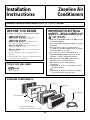
BEFORE YOU BEGIN
Installation Zoneline Air
Instructions Conditioners
Read these instructions completely and carefully.
•
IMPORTANT – Save these
instructions for local inspector’s use.
•
IMPORTANT – Observe all
governing codes and ordinances.
• Note to Installer – Be sure to leave these
instructions with the owner.
•
Note to Owner – Keep these instructions for
future reference.
• Proper installation is the responsibility of the
installer.
• Product failure due to improper installation is not
covered under the Warranty.
Questions? Call 800.GE.CARES (800.432.2737) or Visit our Website at: ge.com
IMPORTANT ELECTRICAL
SAFETY—READ CAREFULLY
CAUTION:
• Follow the National Electrical Code (NEC) or local
codes and ordinances.
• For personal safety, this Zoneline must be properly
grounded.
• Protective devices (fuses or circuit breakers)
acceptable for Zoneline installations are specified
on the nameplate of each unit.
• Do not use an extension cord with this unit.
• Aluminum building wiring may present special
problems—consult a qualified electrician.
• When the unit is in the OFF position, there is
still voltage to the electrical controls.
• Disconnect the power to the unit before
servicing by:
1 Removing the power cord (if it has one) from
the wall receptacle.
OR
2 Removing the branch circuit fuses or turning
the circuit breakers off at the panel.
Phillips screwdriver
TOOLS YOU WILL NEED
12
ZONELINE COMPONENTS
Exterior grille/louver**
** Shipped with the Zoneline unit
** Check the “Essential Elements” list on the unit
Wall case**
Zoneline unit
Room cabinet*
Power supply kit**

13
Installation Instructions
Use the correct wall case
This unit is designed to be installed in a GE plastic or
insulated metal wall case. This minimizes condensation
from forming on the room side of the case.
If the current wall case is not insulated, you can reduce
the possibility of condensation forming by installing
insulation kit RAK901L, available where you purchased
the unit.
NOTE: There are several extra holes in the unit side
flanges for installation in wall cases other than GE.
To avoid damaging the flange insulation, the installer
should use an awl or other sharp tool to puncture the
insulation in the appropriate holes before installing
the attachment screws.
Use the correct outdoor grille
You should use the outdoor grilles shown on the
“Essential Elements” label on the top of the unit.
• If an existing grille is not replaced, capacity and
efficiency will be reduced and the unit may fail to
operate properly or fail prematurely. A deflector kit,
RAK40, may be used with grilles that were not
designed for your new GE Zonelines. The RAK40
contains air deflectors and gaskets that mount to the
unit to direct the hot exhaust air away from the air
intake to allow the unit to function properly. The
grille must have a 65% minimum free area.
• Any vertical deflectors in the existing rear grille should
be removed to decrease condenser air recirculation
that can cause the unit to “short-cycle” and lead
to premature component failure.
Use the correct power cord
Local codes may require the use of arc fault or
leakage current detection devices on 230/208 volt
installations.
Check the “Essential
Elements” label for
important information.
Replacing a ducted unit
New ducted installation:
If this unit is to be installed in a new ducted application
using a duct adapter kit, the kit must be installed before
the unit is placed in the wall case. The installation
instructions are packed with the kit.
Existing ducted installation:
Replacement of an existing ducted unit may require
different components. Request this information from
your sales representative.
• Replacing 230/208 volt units:
See page 14.
• Replacing 265 volt units:
See pages 15 and 16.
Mounting
plate
Duct
Case
REPLACING AN EXISTING UNIT?

Installation Instructions
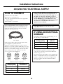
HOW TO CONNECT
IF USING AN ELECTRICAL
SUBBASE
1 Remove the room cabinet.
2 Connect to electrical power.
3 See the special instructions below for applicable
supply voltages.
4 Reinstall the room cabinet.
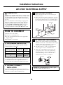
Tandem
15 Amp.
230/208 volt receptacle configuration.
Perpendicular
20 Amp.
Large Tandem
30 Amp.
Order Kit RAK4002A for 230/208 volt direct
connection.
Power cords may include an arc fault interruption or
a leakage current detection interruption device. A
test and reset button is provided on the plug case or
the inline case. The device should be tested on a
periodic basis by first pressing the TEST button and
then the RESET button. If the TEST button does
not trip or if the RESET button will not stay engaged,
discontinue use of the Zoneline and contact a
qualified service technician.
230/208 volt models may be installed using one of
the following electrical subbases:
*Not approved for use on 7000 BTU models.
Electrical subbases provide an enclosure for direct
connection or enclosed receptacles. The subbase kit
includes the power cord.
The instructions provided with the selected subbase kit
must be carefully followed. It is the responsibility of the
installer to ensure the connection of components is
done in accordance with these instructions and all
electrical codes.
Branch Circuit and Proper GE
Unit Amperage Rating Subbase Kit
15 RAK204D15P
20 RAK204D20P
30 RAK204D30P*
A power supply kit must be used to supply power to the
Zoneline unit. The appropriate kit is determined by the
voltage, the means of electrical connection and the
amperage of the branch circuit.
Connections of 208 or 230 volt circuits may be with a
power supply kit or a junction box kit.
All wiring, including installation of the receptacle,
must be in accordance with the NEC and local codes,
ordinances and regulations. Local codes may require
the use of an arc fault or leakage current detection
device on the power cord. Be sure to select the
correct cord for your installation.
Power supply kit
Branch Circuit and Proper GE Power Cord
Unit Amperage Rating with LCDI Device
15 RAK3153
20 RAK3203
30 RAK3303*
14
230/208 VOLT ELECTRICAL SUPPLY
*Not approved for use on 7000 BTU models.

REMOVE JUNCTION BOX
1 Remove the junction box cover by removing the
front two screws.
2 Remove the junction box by removing the top and
bottom rear screws. Note how the tabs on the lower
left side of the junction box serve to hold the side in
place. This will help when the box is being reinstalled.
1
Unit connector
Junction
box cover
Junction
box
15
Installation Instructions
265 VOLT ELECTRICAL SUPPLY
WARNING:
Connection of this 265 V AC product to a branch circuit
MUST be done by direct connection in accordance with
the National Electrical Code. Plugging this unit into a
building mounted exposed receptacle is not permitted
by code.
These models must be installed using the appropriate
GE power supply kit for the branch circuit amperage
and the electrical resistance heater wattage desired.
Use the POWER CONNECTION CHART on page 17
to determine the correct kit required. One of the
following installation methods (A or B) must be used.
CUT AND STRIP THE CORDSET
1 Remove the cordset from the power supply kit.
Measure 6″ down the cord from where it emerges
from the back of the nylon plastic connector
and cut the cord through at this point.
2 Carefully remove 3″ of the cordset insulation
so as to expose the three insulated wires.
3 Strip 3/4″ of the insulation away at the end
of each of the three wires (L1, Neutral and
Ground). Plug the connector fully into place
in the unit mating connector. Be sure the
locking tabs at the sides are engaged.
2
3/4″
3″
Connector
6″
NOTE: Order Kit RAK4002CW to enable a quick
disconnect inside the junction box.
A. FOR SUBBASE INSTALLATION
Electrical subbase kits are available to provide a flexible
enclosure for direct connection.
The instructions provided with the selected subbase kit must
be carefully followed. It is the responsibility of the installer
to ensure the connection of components is done in
accordance with these instructions and all electrical codes.
Branch Circuit and Proper GE Power
Unit Amperage Rating Subbase Kit Supply Kit
15 RAK204E15 RAK5172
20 RAK204E20 RAK5202
30 RAK204E30 RAK5302
B. FOR DIRECT CONNECT
INSTALLATION
If an electrical subbase is not used, direct connection to
branch circuit wiring inside the provided junction box must
be done in accordance with the following steps.
HOW TO CONNECT
1 Remove the room cabinet.
2 Connect to electrical power.
3 See the special instructions below for applicable
supply voltages.
4 Reinstall the room cabinet.

Installation Instructions
16
265 VOLT ELECTRICAL SUPPLY
REINSTALL JUNCTION BOX
• Reinstall the junction box by engaging the left tabs
on the lower right face of the unit, aligning the
screw holes at the top and bottom and driving the
two screws until secure. Be sure that all wire leads
are inside the box and not pinched between the box
and the unit. The green insulated ground wire from
the unit MUST be connected to the branch circuit
ground wire.
Make all wire connections by using appropriate
UL-listed electrical connectors and techniques
(black to black, white to white and green to green).
4
REINSTALL JUNCTION
BOX COVER
1 Carefully tuck all wires and connections back inside
the junction box. Be sure there are no loose
connections or stray uninsulated wires exposed.
2 Place the junction box cover in place. Replace the
two screws removed earlier and tighten securely.
3 Discard the unused portion of the plug and
the cordset.
5
ATTACH CONDUIT
1 Use the round knockout at the bottom of the
junction box to attach conduit coming from the
branch circuit. Remove the knockout, attach the
conduit and bring wires into the junction box.
Leave 6″ of wire free at the end of the conduit
to allow connections to be made.
2 If a fuse and fuseholder are to be used, the
knockout at the top of the box is for mounting
a Buss Fuseholder. Be sure the fuse and fuseholder
are of the same rating as the branch circuit.
Leadwires at the fuse can be either soldered in
place or attached using UL-listed 1/4″ female
(receptacle) crimp connectors.
3
Conduit

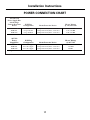
230/208 Volt
Power Supply Kits
with Leakage
Current Detection Wall Plug Heater Wattage
Device Configuration Circuit Protective Device @ 230/208 Volts
RAK3153* Tandem 15 Amp Time Delay Fuse or Breaker 2.55/2.09 KW
RAK3203* Perpendicular 20 Amp Time Delay Fuse or Breaker 3.45/2.82 KW
RAK3303* Large Tandem 30 Amp Time Delay Fuse or Breaker 5.00/4.10 KW
265 Volt
Power Wall Plug Heater Wattage
Supply Kits Configuration Circuit Protective Device @ 265 Volts
RAK5172* Does Not Apply 15 Amp Time Delay Fuse or Breaker 2.55 KW
RAK5202* Does Not Apply 20 Amp Time Delay Fuse or Breaker 3.45 KW
RAK5302* Does Not Apply 30 Amp Time Delay Fuse or Breaker 5.0 KW
*Not approved for use on 7000 BTU models.
Installation Instructions
17
POWER CONNECTION CHART

Installation Instructions
18
INSTALL THE WALL CASE AND
EXTERIOR GRILLE
The RAB71 series or RAB77 wall case must be
properly installed per instructions packed with
the case.
• Remove the corrugated stiffener and the outdoor
protective panel. Use the slit in the outdoor panel
as a handhold and push out.
• Install the exterior grille from the room side
following instructions packed with the grille.
Insulated Wall Case
This unit is designed to be installed in a GE plastic
or an insulated steel wall case. This minimizes
condensation from forming on the room side of
the case.
The RAB71 series wall cases are insulated. Insulation
kit RAK901L is available for use with RAB77 or
existing uninsulated wall cases when needed.
NOTE: For installation with a subbase or duct adapter,
see the instructions packed with those kits.
1
Stiffener
Protective
panel
Slit
PREPARE THE UNIT
• Carefully remove shipping tape and foam shipping
blocks from the room cabinet, compressor and
vent door. There may be multiple blocks and pieces
of shipping tape that need to be removed.
• Remove the room cabinet by pulling it out at the
bottom to release it (1), then lift it up to clear the
rail along the unit top (2).
• If vent door is to be operational, remove shipping
screws from the front side of the vent door, if present.
2
Shipping tape
(Locations may vary)
Remove two
shipping screws
INSTALLING THE ZONELINE

INSTALL THE UNIT INTO THE
WALL CASE
Slide the unit into the wall case and secure with four
screws through the unit flange holes.
3
REPLACE THE ROOM CABINET
Reinstall the room cabinet by hooking the top over
the rail along the unit top (1), then pushing it in at
the bottom (2).
4
Installation Instructions
19
NOTE: There are several extra holes in the unit side
flanges for installation in wall cases other than GE.
To avoid damaging the flange insulation, the installer
should use an awl or other sharp tool to puncture the
insulation in the appropriate holes before installing
the attachment screws.

Installation Instructions
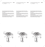
20
OPTIONAL—DRAIN KIT INSTALLATION
Dry Air 25 Series models are designed to improve dehumidification by 25%. Since more moisture will be removed from
the air, there is a greater possibility that water will drip from the wall case than with a standard unit. To prevent this water
from dripping onto external building walls, we recommend the use of RAD10 Drain Kit.
External Drain
See the Installation Instructions
in the RAD10 kit.
Internal Drain
See the Installation Instructions
in the RAD10 kit.
Type “A” screw for metal case or
Type “B” screw for molded case
Square drain holes
Square drain holes
Neoprene sponge gasket
Steel mounting plate
1/2″ O.D. drain tube
Neoprene sponge gasket
Steel mounting plate
Type “A” screw for metal case or
Type “B” screw for molded case
Alternate:
6″ long, 1/2″ O.D. straight
copper tube
Page is loading ...
Page is loading ...
Page is loading ...
Page is loading ...
Page is loading ...
Page is loading ...
Page is loading ...
Page is loading ...
Page is loading ...
Page is loading ...
Page is loading ...
Page is loading ...
Page is loading ...
Page is loading ...
Page is loading ...
Page is loading ...
Page is loading ...
Page is loading ...
Page is loading ...
Page is loading ...
Page is loading ...
Page is loading ...
Page is loading ...
Page is loading ...
Page is loading ...
Page is loading ...
Page is loading ...
Page is loading ...
Page is loading ...
Page is loading ...
Page is loading ...
Page is loading ...
Page is loading ...
Page is loading ...
Page is loading ...
Page is loading ...
Page is loading ...
Page is loading ...
Page is loading ...
Page is loading ...
Page is loading ...
Page is loading ...
Page is loading ...
Page is loading ...
Page is loading ...
Page is loading ...
Page is loading ...
Page is loading ...
Page is loading ...
Page is loading ...
Page is loading ...
Page is loading ...
Page is loading ...
Page is loading ...
Page is loading ...
Page is loading ...
Page is loading ...
Page is loading ...
Page is loading ...
Page is loading ...
Page is loading ...
Page is loading ...
Page is loading ...
Page is loading ...
-
 1
1
-
 2
2
-
 3
3
-
 4
4
-
 5
5
-
 6
6
-
 7
7
-
 8
8
-
 9
9
-
 10
10
-
 11
11
-
 12
12
-
 13
13
-
 14
14
-
 15
15
-
 16
16
-
 17
17
-
 18
18
-
 19
19
-
 20
20
-
 21
21
-
 22
22
-
 23
23
-
 24
24
-
 25
25
-
 26
26
-
 27
27
-
 28
28
-
 29
29
-
 30
30
-
 31
31
-
 32
32
-
 33
33
-
 34
34
-
 35
35
-
 36
36
-
 37
37
-
 38
38
-
 39
39
-
 40
40
-
 41
41
-
 42
42
-
 43
43
-
 44
44
-
 45
45
-
 46
46
-
 47
47
-
 48
48
-
 49
49
-
 50
50
-
 51
51
-
 52
52
-
 53
53
-
 54
54
-
 55
55
-
 56
56
-
 57
57
-
 58
58
-
 59
59
-
 60
60
-
 61
61
-
 62
62
-
 63
63
-
 64
64
-
 65
65
-
 66
66
-
 67
67
-
 68
68
-
 69
69
-
 70
70
-
 71
71
-
 72
72
-
 73
73
-
 74
74
-
 75
75
-
 76
76
-
 77
77
-
 78
78
-
 79
79
-
 80
80
-
 81
81
-
 82
82
-
 83
83
-
 84
84


GE 2800 User manual
- Type
- User manual
- This manual is also suitable for
Ask a question and I''ll find the answer in the document
Finding information in a document is now easier with AI
in other languages
- français: GE 2800 Manuel utilisateur
- español: GE 2800 Manual de usuario
Related papers
-
GE 3800 User manual
-
-
GE AZ35H12D3C User manual
-
GE AZ38H07EAB Owner's manual
-
-
GE AZ39H07DAB Owner's manual
-
-
-
-
GE AZ45E09DAP Owner's Manual and Installation Instructions
Other documents
-
 GE Monogram 3900 series User manual
-
NGS P-SMARTPHONE-0117 Datasheet
-
GEAppliances AZ75H09DAC Technical Service Manual
-
Braeburn 165 User manual
-
Hydrofarm ACF16 User guide
-
Vent-Axia Scope User manual
-
Reznor EBHB Installation guide
-
 Prime-Line N 7298 Installation guide
-
 Prime-Line N 6757 Operating instructions
-
Eaton BRN115AF Instruction Leaflet


