Page is loading ...

PROART DUAL AM/FM TUNER WITH RS232www.altronics.com.au
Manufactured in China for Altronic Distributors Pty Ltd
VIDEO DOOR INTERCOM
S 9413A Base Station & Camera System
S 9414A Additional Base Station
S 9415A Additional Camera Unit
OPERATING INSTRUCTIONS

VIDEO DOOR INTERCOM SYSTEM
Page 2
Included in the box:
• Indoor base station x 1
• Outdoor camera x 1
• Indoor handset x 1
• Expansion junction box x 1
• Mounting bracket x 1
• Mounting screws (4Gx18mm) x 2
• Monitor fixing screws (M3x10mm) x 1
• Power supply
Overview
This system consists of a weatherproof black and white camera module with microphone and a base sta-
tion with handset and screen. Automatically activates the camera and inside display screen when the
“call” button is pushed by a visitor. You may talk to your visitors using the handset on the base unit. The
system can be expanded with up to 4 base stations, enabling the intercom to be answered at different loca-
tions within the home. You can even communicate between indoor stations (ie: as an internal home inter-
com). For homes with multiple entrances a second outdoor camera unit is available separately. Output
contacts for an optional door strike are inbuilt activated by a button on the base unit.
Features
• Weatherproof B&W camera pin hole camera, looks just like a normal door bell
• 4” monitor
• 4 wire connection
• Normally open output for operating door strike relay
• 240V mains operation (power supply included)
• Panic button & output contacts
• Up to 4 indoor base units
• Up to 2 outdoor camera units
Installation
1. Determine the mounting locations for both outdoor camera and base station. To ensure people are
within view when the camera is mounted, bear in mind the camera’s 55 degree viewing angle. Typical
wall mounting height 1450mm. Ensure you are satisfied with the viewing position of the camera and
base station before drilling any holes in your wall.
2. At the selected base station mounting location, attach the mounting bracket to the wall securely. In the
centre of the bracket, drill a hole for the electrical and camera signal wiring.
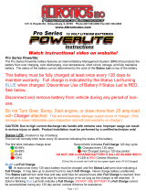
3. Connect the wiring between the base station and camera as per figure 3.
4. Connect the handset to the indoor base station.
5. Slide the base station down against the mounting bracket until the hooks on the bracket secure the unit
in place. Use the small machine screw provided to secure the unit on the wall using the screw hole on
the top of the mounting bracket.
6. Switch on AC power to the unit.
7. Switch on the base station (see figure 1 for location of on/off switch.)
Important mounting guidelines: Do not install the monitor and camera units where they will be exposed
to dirt, moisture, excessive humidity, temperature (+40°C) or constant direct sunlight. Do not select a loca-
tion where it will be exposed to vibration. Select a location close to an AC power outlet where it is easy to
view the screen and operate the monitor.
Installation With Two Indoor Base Stations
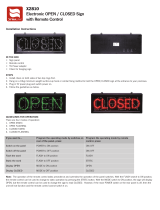
Follow the wiring diagram shown in figure 4. The second base station simply connects into the first base
station via the additional 4 way header terminal.

Page 7
VIDEO DOOR INTERCOM SYSTEM

VIDEO DOOR INTERCOM SYSTEM
Page 6
Troubleshooting
Problem Cause
No power (Power LED off) Insert power cord into power outlet. Ensure the ON/OFF
switch on the bottom of the unit is switched to ON.
Power LED dim Cabling between monitor and camera has a short circuit.
No picture Check the brightness control. Ensure all wires are
connected to the correct terminals, ie: 1 to 1, 2 to 2 etc.
Specifications
Max cabling distance: ..........................................................................................50m (22AWG, 0.65mm 4 core)
Base Station
Voltage requirements: ................................................................................................................100-240V ~ 50Hz
Power consumption: ....................................................................................................Max 35VA, standby 1VA
Monitor screen: ..........................................................................................................................................B&W 4”
Call tone: ............................................................................................................................2 tone xylophone tune
Operating temperature: ..........................................................................................................................0 to 40°C
Weight:..............................................................................................................................................................1.7kg
Dimensions: .................................................................................................................. 180W x 210H x 58D mm
Outdoor camera
Voltage requirements: ................................................................................................................................12V d.c.
Sensor: ....................................................................................................................................................CCD B&W
Viewing angle: ....................................................................................................................................................68°
Operating temperature:........................................................................................................................-40 to 75°C
Dimensions: ......................................................................................................................55W x 104H x 38D mm
Weight:............................................................................................................................................................380gm

VIDEO DOOR INTERCOM SYSTEM
Page 3
Installation With Two Outdoor Cameras
This requires the use of the expansion junction box included with the S 9415A additional outdoor camera
unit. The junction box allows for a maximum of two indoor base stations and two outdoor camera units.
See figure 5 for a wiring diagram of this system.
Operation
When installation is complete switch the power switch to the ON position. Adjust the volume level and
brightness as desired.
When a visitor presses the call button on the camera unit the monitor speaker sounds a chime tone. The
visitors image will appear on the screen. You may choose not to respond by not lifting the handset, the
visitors image will disappear within 20 seconds. To respond to a visitor you can pick up the handset and
talk. The visitors image will remain on screen for 90 seconds or until you put the handset down.
After speaking with the visitor, you may choose to open the door for them. To do this press the unlock
button. Note: You must have an electronic door strike installed in your system for this button to operate.
If you have two base stations installed in your sytem, you can press the call button to communicate with
the second location. This is ideal for two storey or larger homes as an internal intercom.
OFF ON
Stand by
1
2
3
4
5
6
7
8
9
10
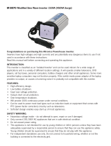
Fig 1. Base Station.
1
2
3
4
5
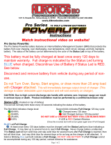
Fig 2. Outdoor Camera Unit
1. Handset
2. Speaker
3. Screen
4. Power LED
5. Monitor button
6. Call button
7. Unlock button
8. Volume level control
9. Power ON/OFF switch
10. Brightness adjustment
1. Camera
2. Microphone
3. Infra-Red LEDs
4. Speaker
5. Call button

VIDEO DOOR INTERCOM SYSTEM
Page 4
Optional Door Lock (Door Strike) Interface
To install door strike, select a 12V d.c. power supply with enough power (current) for your door strike. A
12V 1A d.c. plugpack such as the Altronics M 9274A should be suitable for most door strikes.
Drill cable entry hole in box containing PCB (PCB labelled ‘Altronics strike timer V1’). This box can be
located up to 20m from the door strike.
For connection information see Figure 6.
2
1
3
4
Camera
2
1
3
4
Base Station
2
1
3
4
2
1
3
4
5
6
7
Optional door
lock interface
Jumper
Fig 3. Basic wiring for single camera, single
base station configuration.
Camera
2
1
3
4
Base Station 1
2
1
3
4
2
1
3
4
2
1
3
4
5
6
7
2
1
3
4
2
1
3
4
2
1
3
4
5
6
7
Base Station 2
Optional door
lock interface
Jumper
Jumper
Fig 4. Wiring for two indoor base stations to a
single outdoor camera unit.
See Fig. 6
See Fig. 6

VIDEO DOOR INTERCOM SYSTEM
Page5
Optional Door
Lock Interface Box
Plugpack for
door strike
Doorstrike
To
Intercom
To
12VDC
To
Strike
- +
- +
- +
To Video
Door Intercom
Red +
Black -
Fig 6. Optional door lock interface connection.
Base Station 1
2
1
3
4
2
1
3
4
2
1
3
4
5
6
7
2
1
3
4
2
1
3
4
2
1
3
4
5
6
7
Base Station 2
V+
V-
1
2
3
4
V+
V-
1
2
3
4
V+
V-
1
2
3
4
V+
V-
1
2
3
4
Expansion
Junctionbox
Camera 1
2
1
3
4
Camera 2
2
1
3
4
Jumper
Jumper
Optional door
lock interface
Optional door
lock interface
Fig 5. Wiring for two indoor base stations and two outdoor
camera units. Ensure all wires go to the correct terminals
ie: 1 to 1, 2 to 2 and so on.
To Video Door Intercom
Camera Unit
See Fig. 6
See Fig. 6

Page 8
VIDEO DOOR INTERCOM SYSTEM
For repair or service please contact your place of purchase. Note: Under no circumstances should you
attempt to repair the product yourself or via a non-authorised Altronics service centre as this will
invalidate the warranty! During the warranty period, we undertake to repair or replace your product at
no charge if found to be defective due to a manufacturing fault. The warranty excludes damage by mis-
use, neglect, shipping accident, incorrect installation or no fault found.
NOT FIELD SERVICEABLE.
Distributed by Altronic Distributors Pty. Ltd. Perth. Western Australia.
Phone: 1300 780 999 Fax: 1300 790 999 Internet: www.altronics.com.au
/