
лчиттничюнльтцию.
глтчн.Бзвыдны
www.sotmarket.ru
дбняинфмциятв,
тзывы,бзыиы
Инструкция
SuperMicro MBD-X8STI-F
Перейти в карточку товара
8 800 775 98 98

USER’S MANUAL
Revision 1.2
X8STi-F
X8STi-3F
X8STi
X8STi-LN4

Manual Revision 1.2
Release Date: February 23, 2012
Unless you request and receive written permission from Super Micro Computer, Inc., you may not
copy any part of this document. Information in this document is subject to change without notice.
Other products and companies referred to herein are trademarks or registered trademarks of their
respective companies or mark holders.
Copyright © 2012 by Super Micro Computer, Inc. All rights reserved.
Printed in the United States of America
The information in this User’s Manual has been carefully reviewed and is believed to be accurate.
The vendor assumes no responsibility for any inaccuracies that may be contained in this document,
makes no commitment to update or to keep current the information in this manual, or to notify any
person or organization of the updates. Please Note: For the most up-to-date version of this
manual, please see our web site at www.supermicro.com.
Super Micro Computer, Inc. ("Supermicro") reserves the right to make changes to the product
described in this manual at any time and without notice. This product, including software and docu-
mentation, is the property of Supermicro and/or its licensors, and is supplied only under a license.
Any use or reproduction of this product is not allowed, except as expressly permitted by the terms
of said license.
IN NO EVENT WILL SUPER MICRO COMPUTER, INC. BE LIABLE FOR DIRECT, INDIRECT,
SPECIAL, INCIDENTAL, SPECULATIVE OR CONSEQUENTIAL DAMAGES ARISING FROM THE
USE OR INABILITY TO USE THIS PRODUCT OR DOCUMENTATION, EVEN IF ADVISED OF
THE POSSIBILITY OF SUCH DAMAGES. IN PARTICULAR, SUPER MICRO COMPUTER, INC.
SHALL NOT HAVE LIABILITY FOR ANY HARDWARE, SOFTWARE, OR DATA STORED OR USED
WITH THE PRODUCT, INCLUDING THE COSTS OF REPAIRING, REPLACING, INTEGRATING,
INSTALLING OR RECOVERING SUCH HARDWARE, SOFTWARE, OR DATA.
Any disputes arising between manufacturer and customer shall be governed by the laws of Santa
Clara County in the State of California, USA. The State of California, County of Santa Clara shall
be the exclusive venue for the resolution of any such disputes. Supermicro's total liability for all
claims will not exceed the price paid for the hardware product.
FCC Statement: This equipment has been tested and found to comply with the limits for a Class B
digital device pursuant to Part 15 of the FCC Rules. These limits are designed to provide reason-
able protection against harmful interference in a residential installation. This equipment generates,
uses, and can radiate radio frequency energy and, if not installed and used in accordance with the
manufacturer’s instruction manual, may cause interference with radio communications. However,
there is no guarantee that interference will not occur in a particular installation. If this equipment
does cause harmful interference to radio or television reception, which can be determined by turn-
ing the equipment off and on, you are encouraged to try to correct the interference by one or more
of the following measures:
Reorient or relocate the receiving antenna.
Increase the separation between the equipment and the receiver.
Connect the equipment into an outlet on a circuit different from that to which the
receiver is connected.
Consult the dealer or an experienced radio/television technician for help.
California Best Management Practices Regulations for Perchlorate Materials: This Perchlorate warn-
ing applies only to products containing CR (Manganese Dioxide) Lithium coin cells. “Perchlorate
Material-special handling may apply. See www.dtsc.ca.gov/hazardouswaste/perchlorate”.
WARNING: Handling of lead solder materials used in this product
may expose you to lead, a chemical known to the State of California
to cause birth defects and other reproductive harm.

Preface
This manual is written for system integrators, PC technicians and
knowledgeable PC users. It provides information for the installation and use of the
X8STi/X8STi-F/X8STi-3F/X8STi-LN4 motherboard.
About This Motherboard
The X8STi/X8STi-F/X8STi-3F/X8STi-LN4 supports the Intel
®
Core™ i7
processor and Intel® Xeon® 5500/3500 series processors in an LGA 1366 socket.
These processors support the Intel QuickPath Interconnect (QPI) technology, provid-
ing the next generation point-to-point system interface which replaces the current
Front Side Bus. With the Intel X58 Express chipset built-in, the X8STi/X8STi-F/
X8STi-3F/X8STi-LN4 offers substantial enhancement in system performance with in-
creased bandwidth and unprecedented scalability, optimized for intense-computing
and high-end server platforms. Please refer to our web site (http://www.supermicro.
com/products/) for updates on supported processors. This product is intended to be
installed and serviced by professional technicians.
Manual Organization
Chapter 1-
board and provides detailed information about the chipset.
Chapter 2 provides hardware installation instructions. Read this chapter when in-
stalling the processor, memory modules and other hardware components into the
system. If you encounter any problems, see Chapter 3, which describes trouble-
shooting procedures for video, memory and system setup stored in the CMOS.
Chapter 4 includes an introduction to the BIOS and provides detailed information
on running the CMOS Setup utility.
Appendix A provides BIOS Error Beep Codes.
Appendix B lists the Windows OS Installation Instructions.
Appendix C and Appendix D lists Other Software Program Installation Instructions
and BIOS Recovery Instructions.
Preface
iii

X8STi/X8STi-F/X8STi-3F/X8STi-LN4 User’s Manual
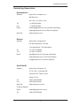
Conventions Used in the Manual:
Special attention should be given to the following symbols for proper installation and
to prevent damage done to the components or injury to yourself:
Danger/Caution: Instructions to be strictly followed to prevent catastrophic
system failure or to avoid bodily injury
Warning: Important information given to ensure proper system installation
or to prevent damage to the components
Note: Additional Information given to differentiate various models or pro-
vides information for correct system setup.
iv

Contacting Supermicro
v
Contacting Supermicro
Headquarters
Address: Super Micro Computer, Inc.
980 Rock Ave.
San Jose, CA 95131 U.S.A.
Tel: +1 (408) 503-8000
Fax: +1 (408) 503-8008
Email: [email protected] (General Information)
[email protected] (Technical Support)
Web Site: www.supermicro.com
Europe
Address: Super Micro Computer B.V.
Het Sterrenbeeld 28, 5215 ML
's-Hertogenbosch, The Netherlands
Tel: +31 (0) 73-6400390
Fax: +31 (0) 73-6416525
Email: [email protected] (General Information)
[email protected] (Technical Support)
[email protected] (Customer Support)
Address: Super Micro Computer, Inc.
4F, No. 232-1, Liancheng Rd.
Chung-Ho 235, Taipei County
Taiwan, R.O.C.
Tel: +886-(2) 8226-3990
Fax: +886-(2) 8226-3991
Web Site: www.supermicro.com.tw
Technical Support:
Email: [email protected]
Tel: +886-(2) 8226-5990

vi
X8STi/X8STi-F/X8STi-3F/X8STi-LN4 User’s Manual
Table of Contents
Preface
About This Motherboard ................................................................................................ 3
Manual Organization ..................................................................................................... 3
Conventions Used in the Manual: ................................................................................. 4
Contacting Supermicro .................................................................................................. 5
Chapter 1 Introduction
1-1 Overview ......................................................................................................... 1-1
Checklist .......................................................................................................... 1-1
Motherboard Features ..................................................................................... 1-7
1-2 Chipset Overview ..........................................................................................1-11
Features of the LGA 1366 Processor and the X58 Chipset ..........................1-11
1-3 PC Health Monitoring .................................................................................... 1-12
Recovery from AC Power Loss ..................................................................... 1-12
Onboard Voltage Monitoring ........................................................................ 1-12
Fan Status Monitor with Software ................................................................. 1-12
CPU Overheat LED and Control .................................................................. 1-12
........................................................................ 1-12
Slow Blinking LED for Suspend-State Indicator ........................................... 1-13
BIOS Support for USB Keyboard.................................................................. 1-13
Main Switch Override Mechanism ................................................................ 1-13
Wake-On-LAN (WOL) ................................................................................... 1-13
1-5 Power Supply ................................................................................................ 1-13
1-6 Super I/O ....................................................................................................... 1-14
1-7 Overview of the Winbond WPCM450 Controller .......................................... 1-14
Chapter 2 Installation
2-1 Static-Sensitive Devices .................................................................................. 2-1
Precautions ..................................................................................................... 2-1
Unpacking ....................................................................................................... 2-1
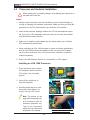
2-2 Processor and Heatsink Installation................................................................ 2-2
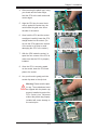
Installing an LGA 1366 Processor .................................................................. 2-2
Installing a Passive CPU Heatsink (#SNK-P0037) ......................................... 2-4
Removing the Heatsink ................................................................................... 2-5
2-3 Mounting the Motherboard into the Chassis ................................................... 2-6
2-4 Installing and Removing the Memory Modules ............................................... 2-7
Installing & Removing DIMMs ......................................................................... 2-7
2-5 Connectors/IO Ports ...................................................................................... 2-10

vii
Table of Contents
Back Panel Connectors and IO Ports ........................................................... 2-10
ATX PS/2 Keyboard and PS/2 Mouse Ports .............................................2-11
Universal Serial Bus (USB) ...................................................................... 2-12
Ethernet Ports .......................................................................................... 2-13
Serial Ports ............................................................................................... 2-14
Video Connector ....................................................................................... 2-15
Front Control Panel ....................................................................................... 2-16
............................................................... 2-17
NMI Button ............................................................................................... 2-17
Power LED .............................................................................................. 2-17
HDD LED/UID Switch ............................................................................... 2-18
NIC1/NIC2/NIC3*/NIC4* LEDs (*NIC3/NIC4: X8STi-LN4) ....................... 2-18
Overheat (OH)/Fan Fail/Blue UID LED .................................................... 2-19
Power Fail LED ........................................................................................ 2-19
Reset Button ........................................................................................... 2-20
Power Button ........................................................................................... 2-20
2-6 Connecting Cables ........................................................................................ 2-21
ATX Main PWR & CPU PWR Connectors .............................................. 2-21
Fan Headers ............................................................................................. 2-22
Chassis Intrusion ..................................................................................... 2-22
Internal Buzzer ......................................................................................... 2-23
Speaker .................................................................................................... 2-23
Overheat/Fan Fail LED ............................................................................ 2-24
NIC3_LED/NIC4_LED (X8STi-LN4 Only) ................................................. 2-24
Onboard Power LED ................................................................................ 2-25
Power Supply I
2
C Connector.................................................................... 2-25
T-SGPIO 0/1 & 3-SGPIO 0/1 Headers ..................................................... 2-26
Alarm Reset .............................................................................................. 2-26
Wake-On-LAN .......................................................................................... 2-27
I-Button (X8STi-3F only) ........................................................................... 2-27
Power Supply Failure ............................................................................... 2-28
............................................................................. 2-28
2-7 Jumper Settings ............................................................................................ 2-29
Explanation of Jumpers ................................................................................ 2-29
LAN Port Enable/Disable ......................................................................... 2-29
CMOS Clear ............................................................................................. 2-30
Watch Dog Enable/Disable ...................................................................... 2-30
PCI Slot_SMB Enable .............................................................................. 2-31
VGA Enable .............................................................................................. 2-31

viii
USB Wake-Up ......................................................................................... 2-32
SAS Enable/Disable (X8STi-3F Only) ...................................................... 2-33
SAS RAID Mode Select (X8STi-3F Only) ................................................ 2-33
JBMC1 (X8STi-F/X8STi-3F Only) ............................................................. 2-34
2-8 Onboard Indicators ........................................................................................ 2-35
LAN 1/LAN 2 LEDs .................................................................................. 2-35
IPMI Dedicated LAN LEDs (X8STi-F/X8STi-3F Only).............................. 2-35
SAS Activity LED (X8STi-3F Only) ........................................................... 2-36
SAS Heartbeat LED (X8STi-3F Only) ...................................................... 2-36
Onboard Power LED ............................................................................................................ 2-37
BMC Heartbeat LED ................................................................................ 2-37
UID-LED .................................................................................................. 2-38
2-9 SATA/SAS and Floppy Drive Connections.................................................... 2-39
SATA/SAS Connections (SAS: for X8STi-3F only) .................................. 2-39
Floppy Connector ..................................................................................... 2-40
Chapter 3 Troubleshooting
3-1 Troubleshooting Procedures ........................................................................... 3-1
3-2 Technical Support Procedures ........................................................................ 3-2
3-3 Frequently Asked Questions ........................................................................... 3-3
3-4 Returning Merchandise for Service................................................................. 3-4
Chapter 4 BIOS
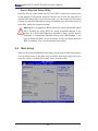
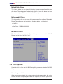
4-1 Introduction ...................................................................................................... 4-1
4-2 Main Setup ...................................................................................................... 4-2
...................................................................... 4-4
4-4 Security Settings ........................................................................................... 4-23
........................................................................................ 4-24
4-6 Exit Options ................................................................................................... 4-25
Appendix A POST Error Beep Codes
Recoverable POST Error Beep Codes ......................................................................A-1
Appendix B Installing the Windows OS
B-1 Installing the Windows OS to a RAID System ................................................B-1
B-2 Installing the Windows OS to a Non-RAID System ........................................ B-2
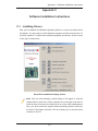
Appendix C Software Installation Instructions
C-1 Installing Drivers ..............................................................................................C-1
.........................................................................C-2
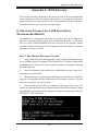
Appendix D - BIOS Recovery
D-1 Recovery Process from a USB Device/Drive (Recommended Method) ............. D-1
D-2 Recovery Process from an IDE/SATA ATAPI Disc Drive ....................................D-2
X8STi/X8STi-F/X8STi-3F/X8STi-LN4 User’s Manual

Chapter 1: Introduction
1-1
Chapter 1
Introduction
1-1 Overview
Checklist
Congratulations on purchasing your computer motherboard from an acknowledged
leader in the industry. Supermicro boards are designed with the utmost attention to
detail to provide you with the highest standards in quality and performance.
Please check that the following items have all been included with your motherboard.
If anything listed here is damaged or missing, contact your retailer.
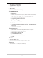
The following items are included in the retail box.
•One (1) Supermicro Mainboard
•Six (6) SATA cables (CBL-0044L)
•
•One (1) I/O shield (MCP-260-00027-0N)
•One (1) Supermicro CD containing drivers and utilities (CDR-X8-UP)
•One (1) User's Manual (MNL-1068)

1-2
X8STi/X8STi-F/X8STi-3F/X8STi-LN4 User’s Manual
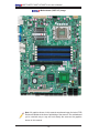
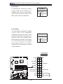
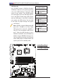
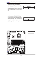
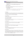
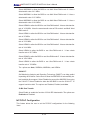
Motherboard (X8STi-3F) Image
Note: All graphics shown in this manual were based upon the latest PCB
Revision available at the time of publishing of the manual. The motherboard
you've received may or may not look exactly the same as the graphics
shown in this manual.

Chapter 1: Introduction
1-3
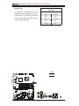
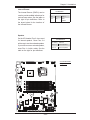
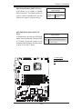
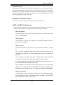
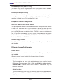
Motherboard Layout
Important Notes to the User
•See Chapter 2 for detailed information on jumpers, I/O ports and JF1 front
panel connections.
•" " indicates the location of "Pin 1".
•Jumpers not indicated are for testing only.
•JBMC1 is reserved for internal testing only. Do not change the jumper setting
pre-set by the manufacturer.
•When LE1 (Onboard Power LED Indicator) is on, system power is on. Unplug
the power cable before installing or removing any components.
LSI 1068E
NIC4 LED
JBMC1

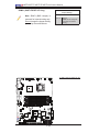
1-4
X8STi/X8STi-F/X8STi-3F/X8STi-LN4 User’s Manual
LSI 1068E
NIC4 LED
JBMC1
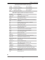
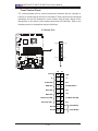
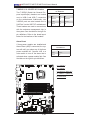
X8STi/X8STi-F/X8STi-3F/X8STi-LN4 Quick Reference
X8STi/X8STi-F/X8STi-3F/X8STi-LN4 Jumpers
Jumper Description Default Setting
JBMC1 BMC Jumper (X8STi-F/-3F Only) Pins 1-2 (Default) (Note Below)
JBT1 CMOS Clear (See Chpt. 2)
JI
2
C1/JI
2
C2 SMB to PCI Slots (See Chpt. 2)
JPG1 Onboard VGA Enable Pins 1-2 (Enabled)
JPL1/JPL2 LAN 1/2 Enable Pins 1-2 (Enabled)
JPL3/JPL4 LAN 3/4 Enable (X8STi-LN4) Pins 1-2 (Enabled)
JPS1 SAS Enable (X8STi-3F) Pins 1-2 (Enabled)
JPS2 SAS RAID Mode Select (X8STi-3F) Closed (Software RAID)
Note: JBMC1 is reserved for internal testing only. Do not change the jumper
setting pre-set by the manufacturer.

Chapter 1: Introduction
1-5
X8STi/X8STi-F/X8STi-3F/X8STi-LN4 Jumpers
JPUSB1 BP USB0/1 Wake-up Pins 1-2 (Enabled)
JPUSB2 FP USB 2/3, 4/5 Wake-up Pins 2-3 (Disabled)
JPUSB3 FP USB 6, 7 Wake-up Pins 2-3 (Disabled)
JWD Watch Dog Timer Enable Pins 1-2 (Reset)
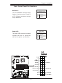
X8STi/X8STi-F/X8STi-3F/X8STi-LN4 Headers/Connectors
Connector Description
COM1/COM2 COM1/2 Serial connection headers
Fans 1~6 System/CPU fan headers
Floppy Floppy Disk Drive connector
I-Button (For X8STi-3F) I-Button for RAID data storage (See P. 2-27 for more info.)
JAR Alarm Reset
JD1 Speaker header (Pins 3/4: Internal, 1~4:External)
JF1 Front Panel Control header
JL1 Chassis Intrusion header
JLED Power LED Indicator header
JOH Overheat LED header
JPW1 24-pin ATX main power connector (required)
JPW2 +12V 8-pin CPU power connector (required)
JPWF Power-Fail indication header
JWOL Wake-On-LAN header
KB/Mouse Keyboard/mouse connectors
LAN1~LAN4 Gigabit Ethernet (RJ45) ports (LAN3/4: X8STi-LN4)
(IPMI) LAN IPMI Dedicated LAN (X8STi-F/-3F only)
NIC3_LED, NIC4_LED LAN 3/LAN 4 LED Connectors for front access (X8STi-LN4)
I-SATA 0~5 Serial_ATA ports
SAS 0~3, 4~7 SAS Ports (X8STi-3F only)
SMB_PS1 PWR supply (I
2
C) System Management Bus
SPKR1 Internal speaker/buzzer
3-SGPIO-0/1 Serial_link IO headers for SAS (X8STi-3F)
T-SGPIO-0/1 Serial General Purpose IO headers (for SATA)
UID Switch
USB0/1, USB 2/3, 4/5,
USB6, 7
Backplane USB 0/1, Front panel accessible USB 2/3, 4/5,
USB 6, USB 7
VGA Onboard Video Port

1-6
X8STi/X8STi-F/X8STi-3F/X8STi-LN4 User’s Manual
X8STi/X8STi-F/X8STi-3F/X8STi-LN4 LED Indicators
LED Description Color/State Status
DP1 BMC Heartbeat LED Indicator Green: Blinking BMC: Normal
LE1 Onboard Standby PWR LED Indicator Green: Solid on PWR On
LE2 UID LED Indicator (used with UID Switch) Blue: Solid on
LES1 SAS Activity (X8STi-3F only) Green: Blinking SAS: Active
LES2 SAS Heartbeat (X8STi-3F only) Yellow: Blinking SAS: Normal
Differences between Main Features of the X8STi/X8STi-F/ X8STi-3F/
X8STi-LN4 Models
X8STi X8STi-F X8STi-3F X8STi-LN4
LAN3/LAN4 No No No Yes
NIC3(LAN3)_LED/ NIC4(LAN4)_LED No No No Yes
JPL3/JPL4 (LAN3/4 Enable) No No No Yes
IPMI 2.0 Support/IPMI Jumper (JBMC1) No Yes Yes No
IPMI Dedicated_LAN No Yes Yes No
I-Button No No Yes No
SAS Ports 0~7 No No Yes No
3-GPIO1/2 (Serial_Link IO) No No Yes No
SAS LEDs (LES1/LES2) No No Yes No

Chapter 1: Introduction
1-7
Motherboard Features
CPU
• Single Intel® Core™ i7 and and Intel® Xeon® 5500/3500 series processors in
an LGA1366 socket.
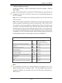
Memory
• Six 240-pin, DDR3 SDRAM DIMM sockets with support for unbuffered ECC or
non ECC 1333/1066/800 MHz memory.
Note: Both Unbuffered ECC and Non-ECC DIMM modules are supported
by the motherboard. Using ECC or Non-ECC memory on your motherboard
depends on the CPU installed. Please see Page 3-3 for more information
on memory support.
• Supports 3-channel memory bus
• Supports DIMM sizes of 256 MB, 512 MB, 1 GB, 2 GB, and 4 GB
Chipset
• Intel® X58 Express Chipset
• Intel ICH10R
Expansion Slots
• One (1) (PCI-Express x16 Gen2 + PCI-Express x8 in x4) slot
• One (1) 32-bit PCI 33MHz slot (Slot 1)
Integrated Graphics
• Matrox G200ew with 8 MB Video Memory
Network Connections
• Two Intel 82574L Gigabit (10/100/1000 Mb/s) Ethernet Controllers for LAN 1
and LAN 2 ports, additional two 82574L for LAN 3 and LAN 4 ports on the
X8STi-LN4 model
• Two (2) or four (4)* RJ-45 Rear IO Panel Connectors with Link and Activity LEDs
(*Four RJ-45 ports are available on the X8STi-LN4 only)
• Single Realtek RTL8201N PHY for the Dedicated IPMI 2.0LAN for the X8STi-
F/-3F
• One (1) RJ45 Rear I/O Panel Dedicated IPMI 2.0 Connector for the X8STi-F/-
3F
• I/O Devices
SATA Connections
• Six (6) SATA ports supported by the Intel ICH10R SATA Controller
• Supports RAID 0, 1, 5, 10 under the Windows OS environment

1-8
X8STi/X8STi-F/X8STi-3F/X8STi-LN4 User’s Manual
• Supports RAID 0, 1, 10 under the Linux OS environment
SAS Connections (for the X8STi-3F only)
• Eight (8) SAS ports supported by the LSI 1068E Controller**
• Supports RAID 0, 1, 5*, 10 under the Windows OS environment
• Supports RAID 0, 1, 5*, 10 under the Linux OS environment
*RAID 5 is supported when the I-Button (AOC-IButton68) is installed on
the motherboard. (I-Button is available on the X8STi-3F only) For more
information on the AOC-IButton68, please refer to http://www.supermicro.
com/products/accessories/addon/AOC-IButton68.cfm.
**For the LSI 1068 Controller User's Guide, please refer to http://www.
supermicro.com/support/manuals/.
Integrated IPMI 2.0 (for the X8STi-F/X8STi-3F only)
• IPMI 2.0 supported by the WPCM450 Server BMC
Note
support/manuals/.
Floppy Drive
•
USB Devices
• Two (2) USB ports (USB 0~1) on the rear IO panel
• Six (6) USB connections for front access (Two Type A connectors: USB 6,
USB 7 and two headers: USB 2/3, 4/5)
Keyboard/Mouse
• PS/2 Keyboard/Mouse ports on the I/O backplane
Serial (COM) Ports
• Fast UART 16550 Connections: one COM port and one header
Super I/O
• Winbond Super I/O 83627DHG
BIOS
• 32 Mb SPI AMI BIOS
®
SM Flash BIOS
• DMI 2.3, PCI 2.3, ACPI 1.0/2.0/3.0, USB Keyboard and SMBIOS 2.5
• ACPI/ACPM Power Management

Chapter 1: Introduction
1-9
• Main switch override mechanism
• Keyboard Wake-up from Soft-Off
• USB Wake-up from Soft-Off
• Wake-on-LAN
• Power-on mode for AC power recovery
PC Health Monitoring
CPU Monitoring
• Onboard voltage monitors for CPU core, Memory Voltage, Chipset Voltage,
+1.8V, +3.3V, +3.3V standby, +5V, +5V, Standby, VBat and ±12V
• CPU 6-Phase switching voltage regulator
• CPU/System overheat LED and control
• CPU Thermal Trip support
• Thermal Monitor 2 (TM2) support
Fan Control
•
speed control
• Low noise fan speed control
System Management
•
• System resource alert via Supero Doctor III
• SuperoDoctor III, Watch Dog, NMI
• I
2
C temperature sensing logic
• Chassis Intrusion Header and Detection
• Pb Free
CD Utilities
•
• Drivers and software for Intel® X58 Express chipset utilities
Dimensions
• ATX form factor, 12" x 9.6" (304.8 x 243.8 mm)

1-10
X8STi/X8STi-F/X8STi-3F/X8STi-LN4 User’s Manual
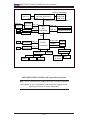
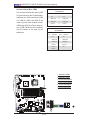
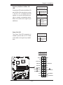
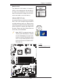
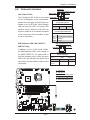
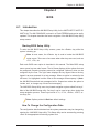
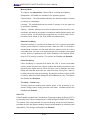
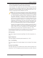
X8STi/X8STi-F/X8STi-3F/X8STi-LN4 System Block Diagram
Note: This is a general block diagram and may not exactly represent
the features on your motherboard. See the following pages for the
Intel
Intel
VRD 11.1
Intel
Intersil
QPI: Up to 6.40 GT/s
PCIE_x16
PCI-E Gen2 x16
X58
W83627DHG
COM1
COM2
FloppyKeyboard
Mouse
SPI
SPI BIOS
ICH10R
LPC I/O
DMI
Intel 82574L
PCIE_x1
RJ45
SATAII /3.0G
USB x 8
SATA x6
USB2.0
DDR3:1333/1066/800
LGA1366_Socket CPU
DIMM_CHB
DIMM_CHA
DIMM_CHC
PCI 32 X 1 Slots
PCI_32_BUS
SAS1068E
PCIE_x8
SAS x8
(X8STi-3F)
BMC WPCM450
IPMI LAN
Onboard
VGA
PCI-E Gen1 x8 in x4
PCIE_x8
(X8STi-3F)
PCIE_x1
( for X8STi-
F/3F only)
(2 DIMMs per Channel, 6 DIMMs total)
Intel 82574L
(X8STi-LN4 only)
(6 DIMMs)
North Bridge
South Bridge
RJ45
PCIE_x1
Intel 82574L
RJ45
(X8STi-LN4 only)
Intel 82574L
RJ45
PCIE_x1

Chapter 1: Introduction
1-11
1-2 Chipset Overview
Built upon the functionality and the capability of the Intel X58 Express chipset, the
X8STi/X8STi-F/X8STi-3F/X8STi-LN4 motherboard provides the performance and
-
tion options optimized for intensive application and high-end server platforms.
The X8STi/X8STi-F/X8STi-3F/X8STi-LN4 supports the Intel® Core™ i7/Intel®
Xeon® 5500/3500 series processors, the Intel X58 Express chipset, and the
ICH10R. With Intel QuickPath Interconnect (QPI) technology built in, the X8STi/
offers the next generation point-to-point system interconnect interface, replacing
the current Front Side Bus technology, providing substantial system performance
enhancement by utilizing serial link interconnections to increase bandwidth and
scalability.
Features of the LGA 1366 Processor and the X58 Chipset
•Intel QuickPath Interconnect link, up to 6.4 GT/s of data transfer rate in each
direction
•Virtualization Technology, Integrated Management Engine support
•Point-to-point cache coherent interconnect, Fast/narrow unidirectional links, and
•Error detection via CRC and Error correction via Link level retry
Page is loading ...
Page is loading ...
Page is loading ...
Page is loading ...
Page is loading ...
Page is loading ...
Page is loading ...
Page is loading ...
Page is loading ...
Page is loading ...
Page is loading ...
Page is loading ...
Page is loading ...
Page is loading ...
Page is loading ...
Page is loading ...
Page is loading ...
Page is loading ...
Page is loading ...
Page is loading ...
Page is loading ...
Page is loading ...
Page is loading ...
Page is loading ...
Page is loading ...
Page is loading ...
Page is loading ...
Page is loading ...
Page is loading ...
Page is loading ...
Page is loading ...
Page is loading ...
Page is loading ...
Page is loading ...
Page is loading ...
Page is loading ...
Page is loading ...
Page is loading ...
Page is loading ...
Page is loading ...
Page is loading ...
Page is loading ...
Page is loading ...
Page is loading ...
Page is loading ...
Page is loading ...
Page is loading ...
Page is loading ...
Page is loading ...
Page is loading ...
Page is loading ...
Page is loading ...
Page is loading ...
Page is loading ...
Page is loading ...
Page is loading ...
Page is loading ...
Page is loading ...
Page is loading ...
Page is loading ...
Page is loading ...
Page is loading ...
Page is loading ...
Page is loading ...
Page is loading ...
Page is loading ...
Page is loading ...
Page is loading ...
Page is loading ...
Page is loading ...
Page is loading ...
Page is loading ...
Page is loading ...
Page is loading ...
Page is loading ...
Page is loading ...
Page is loading ...
Page is loading ...
Page is loading ...
Page is loading ...
Page is loading ...
Page is loading ...
Page is loading ...
Page is loading ...
Page is loading ...
Page is loading ...
Page is loading ...
Page is loading ...
Page is loading ...
Page is loading ...
Page is loading ...
-
 1
1
-
 2
2
-
 3
3
-
 4
4
-
 5
5
-
 6
6
-
 7
7
-
 8
8
-
 9
9
-
 10
10
-
 11
11
-
 12
12
-
 13
13
-
 14
14
-
 15
15
-
 16
16
-
 17
17
-
 18
18
-
 19
19
-
 20
20
-
 21
21
-
 22
22
-
 23
23
-
 24
24
-
 25
25
-
 26
26
-
 27
27
-
 28
28
-
 29
29
-
 30
30
-
 31
31
-
 32
32
-
 33
33
-
 34
34
-
 35
35
-
 36
36
-
 37
37
-
 38
38
-
 39
39
-
 40
40
-
 41
41
-
 42
42
-
 43
43
-
 44
44
-
 45
45
-
 46
46
-
 47
47
-
 48
48
-
 49
49
-
 50
50
-
 51
51
-
 52
52
-
 53
53
-
 54
54
-
 55
55
-
 56
56
-
 57
57
-
 58
58
-
 59
59
-
 60
60
-
 61
61
-
 62
62
-
 63
63
-
 64
64
-
 65
65
-
 66
66
-
 67
67
-
 68
68
-
 69
69
-
 70
70
-
 71
71
-
 72
72
-
 73
73
-
 74
74
-
 75
75
-
 76
76
-
 77
77
-
 78
78
-
 79
79
-
 80
80
-
 81
81
-
 82
82
-
 83
83
-
 84
84
-
 85
85
-
 86
86
-
 87
87
-
 88
88
-
 89
89
-
 90
90
-
 91
91
-
 92
92
-
 93
93
-
 94
94
-
 95
95
-
 96
96
-
 97
97
-
 98
98
-
 99
99
-
 100
100
-
 101
101
-
 102
102
-
 103
103
-
 104
104
-
 105
105
-
 106
106
-
 107
107
-
 108
108
-
 109
109
-
 110
110
-
 111
111


Supermicro MBD-X8STI-F User manual
- Category
- Server/workstation motherboards
- Type
- User manual
Ask a question and I''ll find the answer in the document
Finding information in a document is now easier with AI
Related papers
-
Supermicro X8STi (Standard Retail Pack) User manual
-
Supermicro MBD-X8STI-3F-O User manual
-
-
-
-
Supermicro C7SIM-Q User manual
-
-
-
SUPER MICRO Computer AOC-SASLP-MV8 User manual
-
Other documents
-
 Supero C7SIM-Q User manual
-
ASRock Rack EP2C612D8-2T8R Installation guide
-
-
-
-
SUPER MICRO Computer 5016T-TB User manual
-
 Meiya Pico CyberBlock SAS User manual
-
Dell PowerEdge C6105 Hardware Owner's Manual
-
Gigabyte GA-E350N User manual
-
Intel ICH10R User manual

