
Timpdon Electronics Tel 0161 - 980 7804 Issue 1 – April 2014
Web www.timpdon.co.uk
EMail electronics@timpdon.co.uk Page 1
Introduction
All RC Servos include a bi-directional speed controlled motor, driving an output shaft via a high
reduction gearbox.
Coupled to the output shaft is a feedback potentiometer, measuring the position of the shaft,
which is used within the servo to control the motor speed and direction, such that the position
of the potentiometer, and hence the shaft, always matches a reference position determined by
the joystick setting of the transmitter channel in use.
If the coupling between the output shaft and potentiometer is removed, the motor will
attempt to rotate continuously either clockwise or anti-clockwise depending on whether the
transmitter joystick setting is greater or less than the fixed position of the uncoupled
potentiometer.
If the transmitter setting is equal to the position of the potentiometer, the motor will stop.
On most servos, there are mechanical end stops which prevent the output shaft from rotating
more than approximately 180 degrees, but these can easily be removed, permitting continuous
rotation of the shaft and, in conjunction with a centre neutral transmitter joystick channel, bi-
direction speed control of the servo as a motor gearbox.
The resulting maximum rotation speed of the output shaft can be easily determined from the
published maximum rotation rate of the servo. For example, if the servo is quoted with a slew
time of 0.2 seconds for 60 degrees rotation, this corresponds to 1.2 seconds per revolution, or
50 rev/min, maximum.
This speed is almost ideal for direct drive of anchor and similar winches.
Conversion Procedure
This conversion procedure involves mechanical modifications only. All of the original electronic
control circuits are retained, and used to provide bi-directional motor power in the converted
version.
The description below uses an ACOMS AS17 servo, but most standard servos will be similar in
construction.
Please note, however, that you embark on these modifications at your own risk. No warranty is
given that this procedure will work on all servos. Also some dexterity is required. Do not
attempt this modification unless you are confident in your ability to achieve success.
Also, carefully read and understand all of the procedures outlined below before starting.
Timpdon
Electronics
Technical Note - No. 16
How to Convert a Standard RC Servo
to a Bi-directional RC Controlled
Low Speed Motor Gearbox

Timpdon Electronics Tel 0161 - 980 7804 Issue 1 – April 2014
Web www.timpdon.co.uk
EMail electronics@timpdon.co.uk Page 2
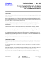
Step 1
Step 2
Step 3
First, locate the fixing screws holding the servo body
parts together.
There are normally four, two on the top on one end,
and two on the underside at the other.
Carefully remove and retain these screws.
Carefully remove the top case moulding from the top
mounting plate by pulling upwards.
Take care not to disturb the lower moulding.
Take careful note of the positions of all gear wheels
so that you can be sure to replace them in the correct
positions later.
Remove the centre gear only from its bearing. Rotate
the output shaft and note that it will only rotate as far as
the end stops.
Now, remove the output shaft and motor gears from
their bearings.
Note that the feedback potentiometer is coupled directly
to the output shaft by a flat shaft.
Note also, the end stops on the output shaft, and servo
body which prevent the output shaft rotating more than
about 180 degrees.

Timpdon Electronics Tel 0161 - 980 7804 Issue 1 – April 2014
Web www.timpdon.co.uk
EMail electronics@timpdon.co.uk Page 3
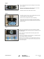
Step 4
Before
After
Step 5
First
Carefully file away the tab on the underside of the
output shaft gear which provides the end stops. You
may also need to file away part of the fixed stops on the
top mounting plate of the servo to ensure that there is
no chance of the shaft hitting the end stops as it rotates.
Second
Carefully drill out the flat down the centre of the output
shaft to a diameter sufficient to ensure that the feedback
potentiometer shaft is clear and can not rotate with the
output shaft.
Use the smallest drill which will clear the potentiometer
shaft to avoid weakening the output shaft moulding.
Temporarily refit the output shaft and check that it will
rotate freely without binding.
If you have your transmitter available, connect the servo
to the channel you will be using to control it, and power
up the servo with the output shaft disconnected.
Set the transmitter joystick to the centre neutral [stop]
position. Then using a small pair of pliers, manually
adjust the position of the potentiometer shaft until the
motor is stationary.
Once the correct position has been found, you may wish
to lock the potentiometer shaft with a small dab of glue.
Ensure that you do not get glue on the output shaft
bearing surfaces.
If a transmitter is not available, set the potentiometer
shaft as closely as possible to the half way position
between its end stops.
This procedure should ensure that you will be able to
calibrate the motor stop position with your transmitter
joystick in the centre neutral position when in use,
within the range of the channel trim adjustment.

Timpdon Electronics Tel 0161 - 980 7804 Issue 1 – April 2014
Web www.timpdon.co.uk
EMail electronics@timpdon.co.uk Page 4
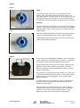
Step 6
Final Comments
Because of the nature of the original servo control system, you will not be able to achieve
much speed control of the motor, except for very small movements of the transmitter joystick.
Over most of the joystick range, the motor will run at its maximum speed.
This will not usually be a problem, however, as the main application for low speed motors is
likely to be for winches, or similar, which normally run at a fixed speed.
A bigger problem may be maintaining zero speed with the transmitter joystick in the neutral
position, as any slight variation of transmitted pulse width will cause the motor to jitter or
creep.
If this is a problem, Timpdon Electronics manufactures a range of servo adaptors which can
overcome this, for a number of specific applications. Please ask for details.
Finally, re-assemble all of the gears on the top plate,
refit the top cover and tighten all fixing screws.
Your converted servo is now ready to use as a slow
speed motor gearbox.
Simply plug it into the required RC receiver channel.
Set the transmitter joystick to the centre neutral
position and, if necessary, adjust the joystick trim until
the output shaft is stationary.
Then check that, as the joystick is moved in one
direction, the output shaft rotates, and that it rotates in
the opposite direction if the joystick direction is
reversed.
-
 1
1
-
 2
2
-
 3
3
-
 4
4


Ask a question and I''ll find the answer in the document
Finding information in a document is now easier with AI


Other documents
-
 FMS Models FMM075PX Owner's manual
-
Volkswagen Transporter 2004 Self-Study Programme
-
GRAUPNER Starlet 50 User manual
-
Dvorak Spider ILD01 User manual
-
Miller JETLINE 9680 MOTORIZED SLIDE REV A Owner's manual
-
 RoboteQ AX2850 User manual
-
 RoboteQ AX500 User manual
-
Danfoss H1 P User guide
-
-
Eurotherm Model 301 Operating instructions


