Page is loading ...

LBI-38625A
Maintenance Manual
MASTR
ΙΙΙ
EMERGENCY POWER OPTIONS
CH1L - Automobile Battery 120 VAC/60 Hz
CH1M - Automobile Battery 230 VAC/50 Hz
CH1R - GEL CELL Battery 120 VAC/60 Hz
CH3A - GEL CELL Battery 230 VAC/50 Hz
THESE SERVICE INSTRUCTIONS ARE FOR USE BY QUALIFIED
PERSONNEL ONLY. TO AVOID ELECTRIC SHOCK DO NOT
PERFORM ANY SERVICING OTHER THAN THAT CONTAINED
IN THE OPERATING INSTRUCTIONS UNLESS YOU ARE
QUALIFIED TO DO SO. REFER ALL SERVICING TO QUALIFIED
SERVICE PERSONNEL.
CAUTION
WARNING
: TO PREVENT FIRE OR ELECTRIC SHOCK HAZARD DO NOT EX-
POSE THIS PRODUCT TO RAIN OR MOISTURE.
CAUTION
: TO PREVENT ELECTRIC SHOCK DO NOT USE THIS (POLAR-
IZED) PLUG WITH AN EXTENSION CORD, RECEPTACLE OR
OTHER OUTLET UNLESS THE BLADES CAN BE FULLY IN-
SERTED TO PREVENT BLADE EXPOSURE.
ericssonz
Ericsson Inc.
Private Radio Systems
Mountain View Road
Lynchburg, Virginia 24502
1-800-528-7711 (Outside USA, 804-528-7711) Printed in U.S.A.

EMERGENCY POWER OPTIONS
CH1L - AUTOMOBILE BATTERY EMERGENCY
POWER (120 Vac/60 Hz VERSION); Adds a
charger and power harness cabling. The automo-
bile battery is external to the base station cabinet
and is purchased separately by the customer for
field installation.
CH1M - AUTOMOBILE BATTERY EMERGENCY
POWER (230 Vac/50 Hz VERSION) Same as
CH1L except for international version charger.
CH1R - GEL CELL BATTERY EMERGENCY POWER
(120 Vac/60 Hz VERSION) Adds a charger,
power cable harnessing, and a gel cell shelf. The
four 12V 25 AH gel cell batteries are not included
in this option. Each of the batteries can be ordered
for field installation per drop ship index item,
V2401.
CHI - GEL CELL BATTERY EMERGENCY POWER
(230 Vac/50 Hz VERSION) Same as CH1R ex-
cept for international version charger.
Copyright© April 1992, Ericsson GE Mobile Communications Inc.
TABLE OF CONTENTS
Page
MIII BASE STATION EMERGENCY POWER OPTIONS . . . . . . . . . . . . . . . . . . . . . . . . . . . . . . 1
CHARGER SPECIFICATIONS . . . . . . . . . . . . . . . . . . . . . . . . . . . . . . . . . . . . . . . . . . . . 2
EMERGENCY POWER OPTION SYSTEM DESCRIPTION . . . . . . . . . . . . . . . . . . . . . . . . . . . . 2
CIRCUIT DESCRIPTION AND THEORY OF OPERATION
FOR THE BATTERY CHARGER . . . . . . . . . . . . . . . . . . . . . . . . . . . . . . . . . . . . . . . . . . . 2
GENERAL . . . . . . . . . . . . . . . . . . . . . . . . . . . . . . . . . . . . . . . . . . . . . . . . . . . . 2
MAIN CHARGING CIRCUITRY . . . . . . . . . . . . . . . . . . . . . . . . . . . . . . . . . . . . . . . . 3
OVERCURRENT PROTECTION . . . . . . . . . . . . . . . . . . . . . . . . . . . . . . . . . . . . . . . . 3
INPUT OVERVOLTAGE PROTECTION . . . . . . . . . . . . . . . . . . . . . . . . . . . . . . . . . . . . 3
OVERTEMPERATURE PROTECTION . . . . . . . . . . . . . . . . . . . . . . . . . . . . . . . . . . . . . 4
BATTERY SWITCHING OPERATION . . . . . . . . . . . . . . . . . . . . . . . . . . . . . . . . . . . . . 4
DEEP DISCHARGE PROTECTION . . . . . . . . . . . . . . . . . . . . . . . . . . . . . . . . . . . . . . 4
ERROR FLAG SIGNALS . . . . . . . . . . . . . . . . . . . . . . . . . . . . . . . . . . . . . . . . . . . . 4
INTERNAL BIAS VOLTAGE SOURCES . . . . . . . . . . . . . . . . . . . . . . . . . . . . . . . . . . . . 4
FLOAT VOLTAGE ADJUST . . . . . . . . . . . . . . . . . . . . . . . . . . . . . . . . . . . . . . . . . . . 4
TROUBLESHOOTING PROCEDURE . . . . . . . . . . . . . . . . . . . . . . . . . . . . . . . . . . . . . . . . 5
PARTS LIST
BATTERY & HARDWARE KITS . . . . . . . . . . . . . . . . . . . . . . . . . . . . . . . . . . . . . . . . 5
BATTERY CHARGER . . . . . . . . . . . . . . . . . . . . . . . . . . . . . . . . . . . . . . . . . . . . . . 8
SCHEMATIC DIAGRAM . . . . . . . . . . . . . . . . . . . . . . . . . . . . . . . . . . . . . . . . . . . . . . . 6
ASSEMBLY DIAGRAM
60 Hz CHARGER . . . . . . . . . . . . . . . . . . . . . . . . . . . . . . . . . . . . . . . . . . . . . . . . 7
MASTR III STATION . . . . . . . . . . . . . . . . . . . . . . . . . . . . . . . . . . . . . . . . . . . . . . 10
INTERCONNECTION DIAGRAM . . . . . . . . . . . . . . . . . . . . . . . . . . . . . . . . . . . . . . . . . . 9
INSTALLATION INSTRUCTIONS . . . . . . . . . . . . . . . . . . . . . . . . . . . . . . . . . . . . . . . . . . 13
This manual covers Ericsson and General Electric products manufactured and sold by Ericsson Inc.
NOTICE!
Repairs to this equipment should be made only by an authorized service technician or facility designated by the supplier.
Any repairs, alterations or substitution of recommended parts made by the user to this equipment not approved by the manu-
facturer could void the user’s authority to operate the equipment in addition to the manufacturer’s warranty.
NOTICE!
This manual is published by
Ericsson Inc.
, without any warranty. Improvements and changes to this manual necessitated
by typographical errors, inaccuracies of current information, or improvements to programs and/or equipment, may be made
by
Ericsson Inc.
, at any time and without notice. Such changes will be incorporated into new editions of this manual. No
part of this manual may be reproduced or transmitted in any form or by any means, electronic or mechanical, including
photocopying and recording, for any purpose, without the express written permission of
Ericsson Inc.
The software contained in this device is copyrighted by the Ericsson Inc. Unpublished rights are reserved under the
copyright laws of the United States.
NOTICE!
LBI-38625
1

CH1L CH1M CH1R CH3A
344A3168P1 10 AMP CHARGER, 60 Hz 1 1
344A3168P2 10 AMP CHARGER, 50 Hz 1 1
344A3696G1 CHARGER KIT 1 1
344A3696G2 CHARGER KIT 1 1
19C852074P1 SUPPORT 1 1 1 1
19C852074P2 SUPPORT 1 1 1 1
19D903719P1 BATTERY STANDBY SHELF 1 1
19C852193P1 BATTERY COVER PANEL 1 1
19D903635 INTERCONNECT DIAGRAM X X X X
19D902845P5 APPLICATION ASSEMBLY X X
19D424751P6 APPLICATION ASSEMBLY X X
344A4051P1 INSTALLATION INSTRUC. X X
344A3168 CHARGER SPECIFICATIONS
Input Voltage Range P1: 121 Vac ±10% for trickle charge or full rated charge
(For Normal Operation State) 121 Vac ±20% for trickle charge only
P2: 230 Vac ± 10% for trickle charge or full rated charge
230 Vac ± 15% for trickle charge only
Input Voltage Range < 70% of nominal line voltage
(For Emergency Power State)
Line Voltage Surge Protection P1: 150 Vac rated M.O.V.
P2: 275 Vac rated M.O.V.
Charger Output Voltage 13.6 Vdc
Rated Charger Current 10.0 amps
Load Current Knee 11.0 ±1.0 amps
Short Circuit Current 4.0 amps max
Charger Output Voltage Ripple < 100 mV p-p (@ + 25°C)
< 200 mV p-p (@ - 30°C)
Duty Cycle (Full Charge) 100% for 8 hours
(Trickle Charge) 100% continuously
Status Line Output
(Normal Operation) 23.5 ±0.5 Vdc
(Emergency Power) Impedance >1 Mohm
Current Sourcing Capability 33 amps max
(A+ to SW A+ port in
Emergency Power State)
Deep Discharge Cutout Voltage 10.5 Vdc
Temperature Range -30° to +60°C
Weight 22 lbs.
EMERGENCY POWER OPTION
SYSTEM DESCRIPTION
The 344A3168 series of chargers are designed to interface
with 19A149978P1, Rev. B or later, or 19A149978P2, Rev. A
or later series power supplies. To retrofit the charger with
19A149978P1, Rev. 0 or A power supplies, or 19A149978P2,
Rev. 0 power supplies, Field Mod Kit 344A4123G1 with mod
instructions 344A4124P1 must be used. Under normal operat-
ing conditions (defined as having the nominal input line voltage
plus a tolerance) the relays K1, K2, and K3 are energized.
344A3168 becomes a charger, providing a full charge of up to
10 amps out of the A + port to the battery system at a constant
voltage until the battery system is fully charged. If the charger
attempts to source more than 10 amps because, for example, a
battery has been deep discharged, then the charger’s current
foldback circuitry will drop the charger voltage for a short time
until the battery has been recharged enough to no longer sink
more than 10 amps. The charger will then revert to providing a
constant voltage charge. The charger then maintains a trickle
charge indefinitely on the battery system to maintain a full
charge.
Without the emergency power options, the power supply’s
10 ohm, 50 watt bleeder resistor R1 is tied to ground through an
external strap, P802. With the emergency power options, P802
is removed, allowing K3, the SW GND (switched ground) relay
in the charger to ground the bleeder resistor through J2-3 to
provide normal operation of the supply. The STATUS line (J2-
1) provides a + 24 Vdc signal to the alarm tone circuitry indi-
cating the system is in the normal operating state.
When the input line voltage drops below 70% of the nomi-
nal line voltage, the charger reverts to the emergency power
state. Current, instead of being sourced from the A + port to the
battery system, is now being delivered from the battery. K1 de-
energizes, and K2 remains energized. This allows up to 33 amps
to flow from the battery to the charger A + port, out of the SW
A + (SWitched A +) port and through the SW A + port of the
power supply. The current is then fed through the power sup-
ply’s load fuses and out through the harnesses to run the base
station’s power amplifier and receiver/system circuitry. K3 also
de-energizes, opening the bleeder resistor circuit. This removes
the 1.2 amp load on the battery that would have drained the bat-
tery at a faster rate. The STATUS line becomes an open circuit
to the alarm tone circuitry indicating the system is in the emer-
gency power state.
When the battery system has discharged to approximately
10.5 Vdc the charger de-energizes K2 to prevent a deep dis-
charge of the battery system. This is important for both gel cells
and automobile batteries but especially for automobile batteries.
Any deep discharge of an automobile battery will affect its ca-
pacity to store energy. Several deep discharges would result in a
premature replacement of the battery. The charger then sits in
"limbo" waiting for the normal operating range line voltage to
reappear.
If the charger has:
1) an overheating condition, or
2) an overvoltage condition which would lead to an over
heating condition;
then the charger will revert to a "shutdown" mode until condi-
tions return to normal. Under normal conditions the SHUT-
DOWN line (J2-2) is at 0.1-0.2 Vdc. When the charger reverts
to the shutdown mode, J2-2 rises to around 2-3 VDC. The
charger remains in shutdown until the condition is corrected.
CIRCUIT DESCRIPTION AND
THEORY OF OPERATION FOR THE
344A3168P1 OR P2 BATTERY
CHARGER
GENERAL
The 344A3168 battery charger has been designed to provide
both system battery charging and relay switched, emergency
power via automobile battery or gel cell battery for the
MASTR II/IIe/MIII series of base stations.
The charger monitors system line voltage for possible inter-
ruptions. During normal operation, the charger maintains full
charge on the emergency power battery by providing a trickle
charge current. In the event of a power source interruption, the
charger sets the STATUS line to the emergency power mode,
discontinues battery charging, and switches the battery on line
to provide emergency backup power for the base station.
Extreme care must be exercised when using an automo-
bile battery for backup emergency power. The automo-
bile battery must not be installed in the base station
cabinet because a buildup of acidic fumes during out-
gassing would damage the base station circuitry. Also,
there could be a dangerous buildup of hydrogen gas in
the cabinet during outgassing which could lead to an
explosion. Even for an automobile battery correctly in-
stalled outside of the cabinet, there could be a danger-
ous concentration of hydrogen gas if the room is not
properly ventilated. It may even be necessary to provide
a "hood" over the battery and an exhaust system to vent
the gas to the out-side world. Follow OSHA (or other
equivalent agency) safety construction rules to deter-
mine a proper design.
WARNING
LBI-38625
2

Several general rules can be applied to estimate charge
time of a lead acid battery system. There is almost a 100% con-
version of electrical energy to stored chemical energy for the
first 80% of battery capacity. If usable capacity is defined to be
at least 80 % of full charge, then the time to reach usable ca-
pacity is: T = 0.8 x AH/C, where T is in hours, AH is in amp-
hours, and C is the average charge rate in amps. To charge the
remaining 20 % to a full charge takes longer because the elec-
trical energy is no longer close to 100 % conversion to stored
chemical energy. The time to a full charge can be estimated as,
T = 1.1 x AH/C, where again T is in hours, AH is in amp-
hours, and C is the average charge rate in amps. Using these
estimates for a ten amp charger, a standard 55 Amp-Hour auto-
mobile battery and a gel cell system that uses four 25 Amp-
Hour batteries in parallel would recharge in the following
times:
Estimates can be provided for air time for a MII/MIII sta-
tion. Assuming a worst case scenario of a 100% transmit duty
cycle, the station air time with a 55 Amp-Hour automobile bat-
tery would be approximately one hour and considerably longer
for a smaller transmit duty cycle. With a four-in-parallel 25
Amp-Hour gel cell system, the station air time for a 100%
transmit duty cycle would be approximately three hours with
again a correspondingly longer air time for a smaller transmit
duty cycle.
MAIN CHARGING CIRCUITRY
Power to the charging circuitry is provided from a 120 Vac,
60 Hz (P1) or 230 Vac/50 Hz (P2) line source connected to the
main power cord (W801). Input power is passed through fuse
F1 (and F2 for P2), which limits input current to 5 amps, and
past varistor VR1. VR1 is a voltage transient surge protector
which clamps the line at approximately 150 Vac (P1) or 275
Vac (P2). This protects the internal circuitry from potentially
harmful line voltage surges.
Line voltage is then applied to transformers T1 and T2
which in parallel step the line voltage down to approxi-
mately 38 Vac. This voltage is then applied to rectifiers D1
and D2 as well as filter capacitors C1, C2, and C3. After rec-
tification and filtering, the unregulated DC voltage is ap-
proximately 20 Vdc.
Charging current then flows through the linear regulator
stage on its way to the battery. The linear regulator is com-
posed of two basic groups. These groups are the series pass
regulator group and the series pass control group.
The series pass regulator group consists of Q1, Q2, Q3,
R1, R2, and R3. In order to control the output voltage of the
charger, the series pass transistors are operated as variable
resistors. If the load on the charger is increased, causing a
drop in the output voltage, the resistance of the series pass
transistors is automatically decreased. With a decrease in se-
ries pass resistance, less voltage is dropped across the tran-
sistors thus increasing the output voltage back to the desired
value.
This implementation has one major drawback, a major
percentage of the total power drawn by the charger is dissi-
pated across the series pass transistors. In order to more ef-
fectively handle this dissipation, three transistors are used.
Resistor R1, R2, and R3 provide negative feedback to the
base of the appropriate transistor preventing unequal current
flow and unequal power dissipation.
The series pass control circuitry is comprised of U3, Q4
and their associated bias resistors and decoupling capacitors.
U3 continuously monitors the output voltage being devel-
oped by the interaction between the load and series pass
transistors. When more ouput voltage is required to maintain
regulation, U3 increases drive to transistor Q4. Q4 provides
the amount of series pass transistor base drive necessary to
decrease their resistance and boost the output voltage back
up to the desired value.
This continuous interaction between the control circuitry
and series pass state forms a closed loop control group
which provides the regulated output voltage to the battery.
Potentiometer R12 varies the amount of voltage feedback in
the control loop thus allowing precise adjustment of the out-
put voltage at which regulation is maintained.
OVERCURRENT PROTECTION
Overcurrent protection is provided via a current foldback
scheme. Resistors R4, R5, and R6 form a current sensing
element. The amount of voltage developed across these re-
sistors is directly proportional to the amount of current flow-
ing through them. This sense voltage is applied to the
regulator control integrated circuit, U3, by means of R9,
R10, and R50. As the current through these sense resistors
increases above approximately 10.5 amps, the sense voltage
and output current to decrease. This current foldback ap-
proach for overcurrent protection decreases the amount of
power dissipated across the series pass transistors during a
faulted condition. The maximum allowable short circuit cur-
rent is less than 3 amps.
INPUT OVERVOLTAGE PROTECTION
Overvoltage protection circuitry is provided to protect
the charger from abnormally high AC line voltages. These
voltages could cause premature failure of the series pass
transistors due to excessive power dissipation. When the line
voltage exceeds the limits specified for normal operation, the
charger senses an abnormal condition and reverts to the
SHUTDOWN mode. The charging current to the battery is
cut off by disabling the regulator control integrated circuit,
U3.
AC line voltage is applied to the input of transformer T3
which then steps down the voltage. This voltage is then recti-
fied and filtered into a DC voltage by D10 and C18. Resistor
R27 sets the response time of the filter to decreasing line
voltages. The resultant DC voltage is directly proportional to
the value of AC line voltage being seen by the charging cir-
cuitry. The DC voltage is then divided by the series combi-
nation of R28, R29, and R30. Potentiometer R29 is used to
adjust for transformer winding ratio tolerances from unit to
unit and is factory set. Capacitor C14 provides addition fil-
tering of the line sense voltage.
The same sense voltage signal provides information for
both the overvoltage and undervoltage sensing circuitry.
U8A provides current buffering to eliminate degradation of
the signal. This buffered signal is then applied to the over-
voltage comparator U7B. When a line overvoltage condition
is sensed, the output of U7B, normally a high impedance,
becomes a very low impedance. This low impedance re-
moves base drive to transistor Q7. When Q7 loses base drive
it turns off allowing the shutdown pin of U3 to go high and
disabling drive to the series pass transistors. This effectively
turns off all charging current to the battery.
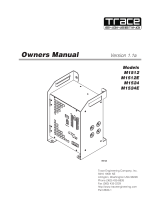
Figure 1 - 344A3168 Charger
With the four-in-parallel gel cell battery system, if one gel
cell becomes defective before the other three, the cus-
tomer can run with only three gel cells in parallel (with re-
duced air time, of course). It is not advisable to run with
only two gel cells in parallel because of excessive charge
current from the charger which would damage the gel
cells. It is good practice when one gel cell battery be-
comes defective to replace all four gel cell batteries be-
cause of uneven charge and discharge characteristics of
new versus old gel cells. For that same reason it is also ad-
visable not to mix different brands of gel cells.
NOTE
Qty. Type Usable Capacity Full Capacity
1 55 Amp-Hour Auto Battery 4.4 Hours 6.0 Hours
4 25 Amp-Hour Gel Cell Batteries 8.0 Hours 11.0 Hours
Potentiometer R29 is specifically adjusted per internal
factory specs to set the proper trip voltages to send the
charger into the SHUTDOWN mode if the limits are ex-
ceeded. With the line voltage and the line frequency set
at nominal values, R29 is adjusted for 3.24 ±0.02 V(@
230 Vac 50Hz) or 3.20 ±0.02 Vdc (@ 121 Vac 60 Hz) at
TP1. AN IMPROPER TUNING OF R29 COULD
CAUSE THE CHARGER’S PASS TRANSISTORS TO
DISSIPATE EXCESSIVE HEAT, RESULTING IN
LOWERED RELIABILITY. THERE SHOULD BE NO
NEED TO ADJUST R29 IN THE FIELD.
CAUTION
LBI-38625
3

Charger overvoltage sensing depends on whether the
charger is in the trickle or full charge mode. The first mode
of operation is for a trickle charge condition in which the
battery charging current is less than 200 milliamps. The al-
lowable line voltage range for this mode of operation is
±20% (P1) or ±15% (P2). The second mode of operation is
for charging of the battery at current up to the maximum out-
put current of 10 amps. The line voltage tolerance range for
this mode of operation is ±10%. It is critical for the charger
to be able to operate over both ranges yet protect itself from
excessive series pass transistor heat dissipation.
The method by which the charger discerns the appropri-
ate line voltage tolerance is by monitoring the amount of
charging current flowing through the current sense resistors
R4, R5, and R6. The current sense voltage developed across
these resistors is applied across the differential amplifier of
U8B. The output of U8B is normally biased at 2.5 Vdc.
However, as the amount of current through the sense resis-
tors increases, (sense voltage increases) the output of U8B
begins to decrease. At approximately 6 amps of charging
current, the output of U8B is low enough to trip the output
of comparator U6B. This normally low impedance output
goes to a high impedance state removing resistor R41 from
its parallel placement with resistor R40. With R40 removed,
the line voltage sense voltage is now only divided by the se-
ries combination of resistors R38 and R40. This decreases
the amount of line sense voltage needed to trip the overvol-
tage comparator U7B. This sets up the ±10% line voltage
tolerance range. When the charging current is less than 6
amps, the output of comparator U6B remains a low imped-
ance, placing R41 in parallel with R40 and setting up the
±20% (±15%) line voltage tolerance.
OVERTEMPERATURE PROTECTION
To protect the charger from abnormal ambient tempera-
ture operating conditions it is equipped with overtemperature
protection. A thermostat, S1, has been attached to the heat
sink in order to monitor the operating temperature of the se-
ries pass transistors. This thermostat is normally closed.
When an abnormal operating temperature is reached, the
thermostat’s switch contacts open and remove base drive to
Q7. As described earlier, removing base drive to Q7 causes
shutdown of the charging regulator. When the temperature of
the heat sink returns to a safe value, the contacts of S1 close
and operation resumes.
BATTERY SWITCHING OPERATION
When the AC line voltage drops below 70% of nominal
voltage, the charger interrupts the charging mode of opera-
tion and switches the battery on line for emergency power
operation. The AC line voltage is sensed as described under
overvoltage protection. The U8A buffered sense voltage is
applied to undervoltage comparator U7A. When the sense
voltage drops below the specified limit, the normally low
impedance output of U7A switches to a high impedance
state. This interrupts base drive current being sourced from
transistor Q5. With the interruption of its base drive current,
Q5 shuts off removing the 24 volt signal coming from U4.
Switching transistor Q5 off also removes drive to relay
K1 and K3. With removal of relay drive the contacts associ-
ated with K1 and K3 switch to their normally closed states.
When this happens, battery charging current can no longer
flow through K1 to the battery. With the K1 relay contacts in
their normally closed position, current flows from the battery
through K2 to the system. In addition, the K3 relay contacts
open thus isolating the switched ground signal from ground.
DEEP DISCHARGE PROTECTION
The battery voltage is sensed at the charger’s A + port.
This voltage provides both bias voltage and signal input to
voltage comparator U6A. The battery voltage is stepped
down by resistors R20 and R21 and compared with the 2.5
Vdc output of voltage reference U5. When the base station
reverts to emergency power, the fully charged battery voltage
starts at around 12.7 Vdc and slowly drops as the battery dis-
charges. The output of U6A remains an open circuit, allow-
ing pull up resistors R24 and R26 to provide drive to Q6 to
energize relay K2. When the battery has discharged to
around 10.5 Vdc the voltage comparator output pulls low,
disabling the drive to Q6 and de-energizing K2. The charger
and base station remain "in limbo" until the line voltage is
restored to the station power supply and charger. The charger
A + port must be greater than 12.25 Vdc before K2 is re-en-
ergized to await the next emergency power state.
ERROR FLAG SIGNALS
In the event of abnormal system operation, the charger
provides two error flag signals as output to the system con-
troller. The first, SHUTDOWN, is an indication of emer-
gency power operation. During normal operation from AC
line voltage the 24 volt signal from transistor Q5 is present
at connector J2-1. When the system is in the emergency power
mode, this signal is removed and becomes a high impedance,
greater than one Megohm.
The second error flag is provided at connector J2-2. This
signal, SHUTDOWN, indicates whether the charger is operat-
ing normally or has been shutdown due to excessive operating
temperature or high line voltage. During normal operation, the
24 VDC output of voltage regulator U4 is applied through R15
to and U3. Due to the U3 interface, this voltage becomes ap-
proximately 3 volts. This signal is independent of transistor
Q5. During shutdown of the charger, this output is pulled down
by transistor Q7 becoming an active low impedance signal.
With removal of the shutdown conditions, this signal automat-
ically returns to the normal operating state.
INTERNAL BIAS VOLTAGE SOURCES
There are three internal bias voltage sources implemented
within the charger to provide internal housekeeping supply
voltages and references. The first is the previously mentioned
24 volt source provided by voltage regulator U4. This source is
supplied directly off the AC line via transformer T1 and T2 as
well as rectifier D6 and filter C10. This source supplies power
for regulator control integrated circuit U3, relays K1, K2 and
also the error flag output signal.
The second source is provided by linear regulator U1. This
regulator supplies power for all the additional control circuitry.
It also acts as a buffer between the control circuitry and the un-
regulated charging voltage from which it draws its own power.
Voltage excursions on the charging bliss are not transmitted to
the control circuitry thus insuring the charger’s ability to pro-
tect itself.
Lastly, is the precision voltage reference provided by regu-
lator U2. This precision 2.5 volt source creates the reference
voltage that is used by all the AC line voltage comparators. The
ability to hold reasonable tolerances on line voltage sense point
requires the use of a high tolerance reference voltage.
FLOAT VOLTAGE ADJUST
Both the automobile batteries and gel cells used with the
new charger are lead acid based batteries. The chemical reac-
tion rates for converting the electrical energy to stored chemi-
cal energy during charging are functions of temperature.
Nominally either battery should be seeing a float voltage of
13.6 Vdc when the ambient temperature of the battery is 77°F
(25° C). As the temperature increases past nominal room tem-
perature the chemical reaction rates increase past nominal and
the float voltage should be lowered to compensate. Conversely,
the float voltage should be increased if the batteries are to see
an average temperature of less than 77°F, but the float voltage
should never exceed 14.4 Vdc. For a nominal 12 Vdc, 6 cell,
lead acid battery the slope of float voltage versus ambient tem-
perature is around -18 mV/°F (-32.4 mV/°C).
By use of the proper float voltage optimum battery usage
can be obtained. If the float voltage is set too high, the battery
can be overcharged, resulting in outgassing and reduction in
lifetime of the battery. If the float voltage is set too low the bat-
tery recharges at a slower rate but more importantly the battery
will permanently lose some of its storage capacity. Most manu-
facturers recommend a float voltage between 13.5 and 13.8
Vdc at room temperature.
The factory has preset the float voltage for 13.6 Vdc. If the
battery will be in an environment where the AVERAGE ambi-
ent temperature will not be 77°F, then the option exists to ad-
just the FLOAT VOLTAGE ADJUST pot for optimum float
voltage. Cable W1 (19B801937P3) is removed from J1 of
charger 344A3168 to present an open circuit load. A high im-
pedance DC voltmeter is attached to -1 (A +) and J1-2 (A-)
and the pot adjusted for optimum float voltage.
The first 344A3168P1, Rev. 0 chargers do not have re-
verse polarity protection designed into the circuitry.
This may allow blowing at transistor Q6 if customers
accidentally reverse the battery cable leads. This pre-
vents the charger from properly switching relay K2 for
emergency power. A production change on
344A3168P1, Rev. A chargers and all 344A3168P2
chargers adds a diode similar to a 1N4004 to the collec-
tor of Q6. Contact Ericsson GE Technical Support for
any additional information.
NOTE
LBI-38625
4

PARTS LIST
TROUBLESHOOTING PROCEDURE
SYMPTOM PROCEDURE
NO CHARGING OUTPUT VOLTAGE CHECK THE FOLLOWING:
PROPER LINE VOLTAGE
OPEN FUSE F1
OPEN TRANSISTOR A1Q4
BAD I.C. A1U3
SHORTED A1Q7
OPEN THERMISTOR A2S1
BAD RELAY A1K1
BAD I.C. A1U4
BAD I.C. A1U7
OUTPUT VOLTAGE TOO HIGH
(GREATER THAN 14 Vdc)
CHECK THE FOLLOWING:
SHORTED TRANSISTOR A2Q1
SHORTED TRANSISTOR A2Q2
SHORTED TRANSISTOR A2Q3
BAD POTENTIOMETER A1R12
BAD I.C. A1U7
OUTPUT VOLTAGE TOO LOW
(GREATER THAN 1 Vdc
LESS THAN 13.6 Vdc)
CHECK THE FOLLOWING:
LOAD TOO HIGH (IN FOLDBACK)
BAD POTENTIOMETER A1R12
BAD I.C. A1U3
SHORTED A1C4
BLOWN FUSE F1 CHECK THE FOLLOWING:
SHORTED VARISTOR A1RV1
SHORTED TRANSFORMER T1
SHORTED TRANSFORMER T2
SHORTED TRANSFORMER A1T3
SHORTED DIODE A1D1
SHORTED DIODE A1D2
SHORTED DIODE A1D6
SHORTED DIODE A1D10
SHORTED CAPACITOR A1C1
SHORTED CAPACITOR A1C2
SHORTED CAPACITOR A1C3
SHORTED CAPACITOR A1C10
SHORTED CAPACITOR A1C18
BATTERY NOT SWITCHING TO SYSTEM
BACKUP
CHECK THE FOLLOWING:
BAD RELAY A1K1
BAD RELAY A1K2
OPEN TRANSISTOR A1Q6
BAD I.C. U5
BAD I.C. U6
SHORTED TRANSISTOR A1Q5
STATUS ERROR FLAG NOT PRESENT CHECK THE FOLLOWING:
LINE VOLTAGE TOO LOW
OPEN TRANSISTOR A1Q5
BAD I.C. A1U4
BAD I.C. A1U7
OPEN DIODE A1D9
SWITCHED GROUND NOT CONNECTED CHECK THE FOLLOWING:
LINE VOLTAGE TOO LOW
BAD RELAY A1K3
OPEN TRANSISTOR A1Q5
BAD I.C. A1U4
ANY OTHER FAULT CONSULT THE FACTORY
SYMBOL PART NO. DESCRIPTION
MIII AUTOMOBILE BATTERY KIT
344A3696G1
W1 19B801937P4 Power Cable
W2 19B801970P1 Power Cable
W3
W4 19B801970P3 Power Cable
W5 19B801970P4 Power Cable
W6 Not Used
W7 Not Used
W8 Not Used
1 344A3450G1 Hardware Kit
2 Not Used
3 Not Used
4 Not Used
MIII GEL CELL BATTERY KIT
344A3696G2
W1 19B801937P4 Power Cable
W2 19B801970P1 Power Cable
W3 Not Used
W4 Not Used
W5 Not Used
W6 19B801970P5 Power Cable
W7 19B801970P6 Power Cable
W8 19C327801G1 Harness
1 Not Used
2 344A3450G5 Hardware Kit
3 19B802073PI Rear support
4 19B802067P1 Cover
HARDWARE KIT
344A3450G1
1 7I60861P33 SPRING NUT
2 19A134011P2 SCREW
3 7160861P4 SPRING NUT
4 N145P1507B6 TAPPED SCREW
HARDWARE KIT
344A3450G5
1 7160861P33 SPRING NUT
2 19A134011P2 SCREW
I5 N403P16B6 LOCK WASHER
17 N80P16008B6 MACHINE SCREW
18 N403PI9B6 LOCK WASHER
19 N402P39B6 FLAT WASHER
20 N80P15012B6 MACHINE SCREW
21 N402P38B6 FLAT WASHER
*COMPONENTS, ADDED, DELETED OR CHANGED BY PRODUCTION CHANGES
BATTERY AND HARDWARE KITS
LBI-38625
5

SCHEMATIC DIAGRAM
60 Hz CHARGER
(289PS5, Rev. A)
LBI-38625
6

ASSEMBLY DIAGRAM
60 Hz CHARGER
(XP-289PS5, Rev. 5)
LBI-38625
7

PARTS LIST
SYMBOL PART NO. DESCRIPTION
Battery Charger Top Assembly
PS5A1 M29/91035300 Printed Circuit Card Assembly
PS5A2 M29/91037100 Power Transistor Heat Sink Assembly
PS5W1 M29/25011200 J1 Output Power Conn. Harness
Assembly
PS5W2 M29/25011300 J2 Test Connector Harness Assembly
PSW801 M29/11022301 AC Cord Set
PS5T1 M29/289P1 Main Power Transformer
PS5T2 M29/289P1 Main Power Transformer
M29/7064200 Chassis
M29/7064300 Top Cover
M29/7064400 Front Panel
M29/9014200 Fuse Holder
M29/9013900 Fuse, Bussman, MDL-5
M29/31023000 Insulator, PWB To Chassis
M29/11022000 Strain Relief, HEYCO, 1200
M29/7064700 Heat Sink Skid
M29/11024500 Cable Tie
M29/22045900 Spacer, #10 X .375, Nylon
M29/22046000 Spacer, #10 X .125, Nylon
M29/22046401 Screw, M3-5 X .5O0, TORX Head
M29/22046400 Screw, M3-5 X 390, TORX Head
M29/22028900 Screw, #4-40 X .375, HEX Head,
Thd. Rolling
M29/22046000 Washer, Sboulder, #10
M29/22041501 Nut, #6-32, Keeper, 1/8 Tbk.
M29/22041502 Nut, #8-32, Keeper, 1/8 Thk.
M29/22041503 Nut, #10-32, Keeper, 1/8 Thk.
Printed Circuit Card Assembly
PS5A1
M29/91035300
C1 M29/17033400 Capacitor, 10,000 µF, 35 v.,
Electrolytic
C2 M29/17033400 Capacitor, 10,000 µF, 35 v.,
Electrolytic
C3 M29/17033400 Capacitor, 10,000 µF, 35 V.,
Electrolytic
C4 M29/17031901 Capacitor, 2,200 µF, 25 V.,
Electrolytic
C5 M29/17018100 Capacitor, 0.1 µF, 50 V., Ceramic
C6 M29/17018107 Capacitor, .001 µF, 100 V., Ceramic
C7 M29/17018100 Capacitor, 0.1 µF, 50 V., Ceramic
C8 M29/17018100 Capacitor, 0.1 µF, 50 V., Ceramic
C9 M29/17018107 Capacitor, .001 µF, 100 V., ceramic
C10 M29/17016202 Capacitor, 470 µF, 50 V., Electrolytic
C11 M29/17016202 Capacitor, 470 µF, 50 V., Electrolytic
C12 M29/17018107 Capacitor, .001 µF, 100 V., Ceramic
C13 M29/17018214 Capacitor, .0022 µF, 100 V., Ceramic
C14 M29/17018100 Capacitor, 0.1 µF, 50 V., Ceramic
C15 M29/17018214 Capacitor, .0022 µF, 100 V., CeramIc
C16 M29/17018214 Capacitor, .0022 µF, 100 V., Ceramic
C17 M29/17018214 Capacitor, .0022 µF, 100 V., Ceramic
C18 M29/17016202 Capacitor, 470 µF, 50 V., Electrolytic
D1 M29/18027200 Rectifier, Dual Gen. Instruments,
30CPQ000
D2 M29/18027200 Rectifier, Dual Gen. Instrument.,
30CPQ090
D3 M29/18018004 Rectifier, General Purpose, UF4002
*COMPONENTS, ADDED, DELETED OR CHANGED BY PRODUCTION CHANGES
BATTERY CHARGER
344A3168P1
ISSUE 1
SYMBOL PART NO. DESCRIPTION
D4 M29/18018004 Rectifier, General Purpose, UF4002
D5 M29/18018004 Rectifier, General Purpose, UF4002
D6 M29/19007500 Rectifier Bridge, Gen. Instrument.,
W04M
D7 M29/18018004 Rectifier, General Purpose, UF4002
D8 M29/18018004 Rectifier, General Purpose, UF4002
D9 M29/18018004 Rectifier, General Purpose, UF4002
D10 M29/18018004 Rectifier, General Purpose, UF4002
D11 M29/18018004 Rectifier, General Purpose, UF4002
D12 M29/18018004 Rectifier, General Purpose, UF4002
D13 M29/18018004 Rectifier, General Purpose, UF4002
D14 M29/13048104 Rectifier, General Purpose, UF4002
J1 M29/13048100 Connector, Faston Tab, Amp, 62650-1
J2 M29/13048100 Connector, Faston Tab, Amp, 62650-1
J3 M29/40024401 Connector, 6 Pos., Amp, 640445-6
J4 M29/40024401 Connector, 6 Pos., Amp, 640445-6
J5 M29/40024402 Connector, 8 Pos., Amp, 640445-8
J6 M29/40024402 Connector, 8 Pos., Amp, 640445-8
J7 M29/13048100 Connector, Faston Tab, Amp, 62650-1
J8 M29/13048100 Connector, Faston Tab, Amp, 62650-1
J9 M29/13048100 Connector, Faston Tab, Amp, 62650-1
J10 M29/13048100 Connector, Faston Tab, Amp, 62650-1
J11 M29/13048100 Connector, Faston Tab, Amp, 62650-1
J12 M29/13048100 Connector, Faston Tab, Amp, 62650-1
J13 M29/13048100 Connector, Faston Tab, Amp, 62650-1
J14 M29/13048100 Connector, Faston Tab, Amp, 62650-1
J15 M29/13048100 Connector, Faston Tab, Amp, 62650-1
K1 M29/20003700 Relay, 12 V., 40 A., SPDT, P&B,
VF4-15H13
K2 M29/20004000 Relay, 12 V., 40 A., SPST, AROMAT,
CB1AF-P-12V
K3 M29/20003600 Relay, 12 V., 5 A., SPST, AROMAT,
J S1AE-DC24V
Q1 M29/18030800 Transistor, Power, NPN, 2N5885
Q2 M29/18030800 Transistor, Power, NPN, 2N5885
Q3 M29/18030800 Transistor, Power, NPN, 2N5885
Q4 M29/18017600 Transistor, Power, NPN, TIP31C
Q5 M29/18023500 Transistor, Power, PNP, TIP32C
Q6 M29/18023200 Transistor, Gen. Purpose, NPN,
MPS2222A
Q7 M29/18023200 Transistor, Gen. Purpose, NPN,
M352222A
R1 M29/16013001 Resistor, 0.15, 5 W., 1%,
Ceramic Wire Wound
R2 M29/16013001 Resistor,0.15,SW., 1%,
Ceramic Wire Wound
R3 M29/16013001 Resistor, 0.15, 5 W.,1%,
Ceramic Wire Wound
R4 M29/16013900 Resistor, 0.12, 5 W., 1%,
Ceramic Wire Wound
R5 M29/16013900 Resistor, 0.12, 5 W., 1%,
Ceramic Wire Wound
R6 M29/16013900 Resistor, 0.12, 5 W., 1%,
Ceramic Wire Wound
R7 M29/16001573 Resistor, 1K, 1/2 W., 5%, Carbon Film
R8 M29/16001464 Resistor, 3.09K, 1/4 W., 1%, Metal Film
R9 M29/16001456 Resistor, 274, 1/4 W., 1%, Metal Film
R10 M29/16001525 Resistor, 10K, 1/4 W., 1%, Metal Film
R11 M29/16001448 Resistor, 38.3K, 1/4 W., 1%, Metal Film
R12 M29/16013500 Potentiometer, 1K, 1 Turn, Cermet
R13 M29/160011449 Resistor, 8.25K, 1/4 W., 1%, Metal Film
R14 M29/160011456 Resistor, 274, 1/4 W., 1%, Metal Film
R15 M29/16001525 Resistor, 10K, 1/4 w., 1%, Metal Film
SYMBOL PART NO. DESCRIPTION
R16 M29/16001447 Resistor, 4.32K, 1/4 W., 1%, Metal Film
R17 M29/16001459 Resistor, 237, 1/4 W., 1%, Metal Film
R18 M29/16001595 Resistor, 5.11K, 1/4 W., 1%, Metal Film
R19 M29/16001595 Resistor, 5.11K, 1/4 W., 1%, Metal Film
R20 M29/16001458 Resistor, 56.5K, 1/4 W., 1%, Metal Film
R21 M29/16001525 Resistor, 10K, 1/ 4W., 1%, Metal Film
R22 M29/16001577 Resistor, 7.5K, 1/4 W., 1%, Metal Film
R23 M29/16001577 Resistor, 7.5K, 1/4 W., 1%, Metal Film
R24 M29/16001595 Resistor, 5.1K, 1/4 W., 1%, Metal Film
R25 M29/16001465 Resistor, 274K, 1/4 W., 1%, Metal Film
R26 M29/16001525 Resistor, 10K, 1/4 W., 1%, Metal Film
R27 M29/16001595 Resistor 5.11K, 1/4 W., 1%, Metal Film
R28 M29/16001446 Resistor, 45.3K, 1/4 W., 1%, Metal Film
R29 M29/16007503 Potentiometer, 2K, 10 Turn, Cermet
R30 M29/16001477 Resistor, 3.24K, 1/4 W., 1%, Metal Film
R31 M29/16001525 Resistor, 10K, 1/4 W., 1%, Metal Film
R32 M29/16001591 Resistor, 1.27K, 1/4 W., 1%, Metal Film
R33 M29/16001591 Resistor, 1.27K, 1/4 W., 1%, Metal Film
R34 M29/16001599 Resistor, 2.00K, 1/4 W., 1%, Metal Film
R35 M29/16001591 Resistor, 1.27K, 1/4 W., 1%, Metal Film
R36 M29/16001590 Resistor, 4.75K, 1/4 W., 1%, Metal Film
R37 M29/16001595 Resistor, 5.11K, 1/4 W., 1%, Metal Film
R38 M29/16001591 Resistor, 1.27K, 1/4 W., 1%, Metal Film
R39 M29/16001595 Resistor, 5.11K, 1/4 W., 1%, Metal Film
R40 M29/16001478 Resistor, 3.09K, 1/4 W., 1%, Metal Film
R41 M29/16001479 Resistor, 7.15K, 1/4 W., 1%, Metal Film
R42 M29/16001470 Resistor, 9.31K, 1/4 W., 1%, Metal Film
R43 M29/16001464 Resistor, 3.57K, 1/4 W., 1%, Metal Film
R44 M29/16001471 Resistor, 21.3K, 1/4 W., 1%, Metal Film
R45 M29/16001525 Resistor, 10K, 1/4 W., 1%, Metal Film
R46 M29/16001582 Resistor, 49.9K, 1/4 W., 1%, Metal Film
R47 M29/16001582 Resistor, 49.9K, 1/4 W., 1%, Metal Film
R48 M29/16001525 Resistor, 10K, 1/4 W., 1%, Metal Film
R49 M29/16001525 Resistor, 10K, 1/4 W., 1%, Metal Film
R50 M29/16001526 Resistor, 100, 1/4 W., 1%, Metal Film
RV1 M29/18008013 Metal Oxide Variator, 150 V., GE,
V150LA20A
T1 M29/FS56-020 Transformer
U1 M29/19005701 Int. Circuit, Voltage Regulator, LM78L15
U2 M29/19010500 Int. Circuit, Reference Voltage, AD680
U3 M29/19009900 Int. Circuit, Lin, Reg. Controller, SG3532
U4 M29/19002101 Int. Circuit, Voltage Regulator, LM317
U5 M29/19009100 Int. Circuit, Voltage Reference, TL431C
U6 M29/19010000 Int. Circuit, Dual Comparator, LM393
U7 M29/19010000 Int. Circuit, Dual Comparator, LM393
U8 M29/19006000 Int. Circuit, Dual Operational Amp.,
LM358
VR1 M29/18001443 Zener Diode, 13 V., 1N964B
M29/33019700 Printed Circuit Card
M29/11023500 Heat Sink, Thermalloy
M29/11022400 Heat Sink
M29/31016703 Thermal Pad
M29/22027710 Screw, #44-40 X .500, HEX Head,
Zinc Plated
M29/22041500 Nut, #4-40, Keeper, 1/8 Thk.
M29/22041503 Nut, #10-32, Keeper, 1/8 Thk.
M29/22045500 Stud, Pem, #10-32 X .500
M29/13040200 Terminal, Wire, Amp, 640311-1
M29/27185266 Wire, 18 AWG, Blue, UL1452BL
M29/27185222 Wire, 18 AWG, Red, UL1452RD
M/29/27185244 Wire, 18 AWG, Yellow, UL1452YL
SYMBOL PART NO. DESCRIPTION
Power Transistor Heat Sink Assembly
PS5A2
M29/91037100
Q1 M29/18030800 Transistor, Power, NPN, 2N5885
Q2 M29/18030800 Transistor, Power, NPN, 2N5885
Q3 M29/18030800 Transistor, Power, NPN, 2N5885
S1 M29/9016700 Thermostat, SPST, Norm. Closed
M29/11024700 Heat Sink
M29/11024800 Heat Sink
M29/11025000 Corner Block
M29/31023200 Thermal Pad
M29/13051800 Socket, T0-3
M29/7062500 Cover, T0-3
M29/22040000 Screw, #6-32 X .250, Pan Head,
Zinc Plated
M29/22009008 Screw, #6-32 X .500, Pan Head,
Zinc Plated
M29/22009007 Screw, #6-32 X .625, Pan Head,
Zinc Plated
J1 Output Conn. Harness Assembly
P85W1
M29/25011200
J1 M29/40028600 Connector, 4 Pos., Amp, 641685-2
M29/13052600 Terminal, Connector, Amp, 350650-1
M29/13053900 Terminal, Ring, Amp, 52263
M29/26080499 Wire, 8 AWG, White, UL1028WH
M29/26080400 Wire, 8 AWG, Black, UL1028BK
M29/26080422 Wire, 8 AWG, Red, UL1028RD
J2 Test Connector Harness Assembly
PS5W2
M29/23011300
J2 M29/40013002 Connector, 3 Pcs., Amp, 1-480701-0
M29/13037600 Terminal, Connector, Amp, 350218-1
M29/13024900 Terminal, Faston, Amp
M29/26160355 Wire, 16 AWG, Green, UL1015GN
M29/26160399 Wire, 16 AWG, White, UL1015WH
M29/26160300 Wire, 16 AWG, Black, UL1015BK
F1 AC Fuse Wire Assembly
W3, W4
M29/250074271
M29/13024900 Terminal, Faston, Amp
M29/26166600 Wire, 16 AWG, Black, UL1509BK
Thermostat Wire Assembly
W5, W6
M29/250074272
M29/13024900 Terminal, Faston, Amp
M29/26166600 Wire, 16 AWG, Black, UL1509BK
LBI-38625
8

INTERCONNECTION DIAGRAM
MASTR III STATION
WITH EMERGENCY POWER
(19D903635, Sh. 3, Rev. 2)
LBI-38625
9

ASSEMBLY DIAGRAM
MASTR III STATION
(19D902845, Sh. 10, Rev. 2)
LBI-38625
10

ASSEMBLY DIAGRAM
MASTR III STATION
(19D902845, Sh. 11, Rev. 1)
LBI-38625
11

ASSEMBLY DIAGRAM
MASTR III STATION
(19D902845, Sh. 12, Rev. 1)
LBI-38625
12

BATTERY SHELF
(344A4051, Sh. 1, Rev. 1)
INSTALLATION INSTRUCTIONS
LBI-38625
13
/