Hitachi N 5008AC Technical And Service Manual
- Type
- Technical And Service Manual

POWER TOOLS
TECHNICAL DATA
AND
SERVICE MANUAL
STAPLER
N 5008AC
SPECIFICATIONS AND PARTS ARE SUBJECT TO CHANGE FOR IMPROVEMENT
LIST No. E003 Oct. 2001
N
MODEL
N 5008AC

REMARK:
Throughout this TECHNICAL DATA AND SERVICE MANUAL, a symbol(s)
is(are) used in the place of company name(s) and model name(s) of our
competitor(s). The symbol(s) utilized here is(are) as follows:
Symbols Utilized
Competitors
Company Name
Model Name
SENCO
SNS40
R
PASLODE
3200-S16P
Y
BOSTITCH
T50S4
P
PORTER CABLE
MS200
U

1. PRODUCT NAME ........................................................................................................................... 1
2. MARKETING OBJECTIVE ............................................................................................................. 1
3. APPLICATIONS .............................................................................................................................. 1
4. SELLING POINTS .......................................................................................................................... 1
5. SPECIFICATIONS .......................................................................................................................... 2
5-1. Specifications .................................................................................................................................. 2
5-2. Staple Selection .............................................................................................................................. 3
5-3. Staple Driving Force ....................................................................................................................... 4
5-4. Optional Accessories ...................................................................................................................... 4
6. COMPARISONS WITH SIMILAR PRODUCTS .............................................................................. 5
7. PRECAUTIONS IN SALES PROMOTION ..................................................................................... 6
7-1. Instruction Manual .......................................................................................................................... 6
7-2. Warning Label ................................................................................................................................. 6
7-3. Related Laws and Regulations ....................................................................................................... 7
8. MECHANISM AND OPERATION PRINCIPLE ............................................................................... 8
8-1. Mechanism ..................................................................................................................................... 8
8-2. Operation Principle ......................................................................................................................... 9
9. TROUBLESHOOTING GUIDE ..................................................................................................... 13
9-1. Troubleshooting and Correction .................................................................................................... 13
9-2. Possible Causes and Corrections of Air Leakage......................................................................... 15
10. DISASSEMBLY AND REASSEMBLY ........................................................................................ 17
10-1. General Precautions in Disassembly and Reassembly .............................................................. 17
10-2. Disassembly and Reassembly of the Output Section ................................................................. 18
10-3. Disassembly and Reassembly of the Control Valve Section ...................................................... 21
10-4. Disassembly and Reassembly of the Driving Section and the Magazine Section ...................... 22
11. INSPECTION AND CONFIRMATION AFTER REASSEMBLY .................................................. 23
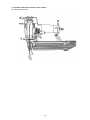
12. STANDARD REPAIR TIME (UNIT) SCHEDULES ..................................................................... 24
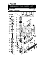
Assembly Diagram for N 5008AC
CONTENTS
Page

--- 1 ---
1. PRODUCT NAME
Hitachi Stapler, Model N 5008AC [50 mm (2")]
2. MARKETING OBJECTIVE
The Model N 5008AC, medium crown stapler is an upgraded version of the current Model N 5008AB (OEM),
equipped with the same output sections as the Model NT 65A2, NV 50AP2 and NV 45AB that are well reputed
with its rapid driving and quick response, and the newly designed driving and magazine sections. Primary
differences from the Model N 5008AB are described below.
(1) The weight of the Model N 5008AC is 2.0 kg (4.4 lbs.) and it is lighter than the current Model N 5008AB about
500 g (1.2 lbs.) thanks to the adoption of the plastic magazine. The staple shoulder sliding portion of the
magazine is wear-resistant.
(2) The driving speed is faster than the Model N 5008AB thanks to the adoption of the 2-valve/cylinder drive
system that is well reputed in the current Models NT 65A2, NV 50AP2 and NV 45AB for easier operation
(detailed data is described on later pages).
(3) The handle is equipped with a cylindrical grip rubber for comfortable fitting and durability.
(4) The driving depth is easily adjustable by the accessory wrench.
3. APPLICATIONS
Construction work such as well sheathing, roof decking and subflooring
Mobile and modular home construction
Making wooden boxes, and expendable pallets
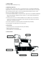
4. SELLING POINTS
Rapid driving and
quick response
Grip rubber
Plastic magazine
with stainless plate
Quick jam-release
Depth adjustment

--- 2 ---
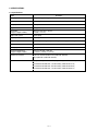
Optional accessories
Staple capacity
2.0 kg (4.4 lbs.)
1.14 ltr/cycle at 7 kgf/cm
2
(0.040 ft
3
/cycle at 100 psi) (1.14 ltr/cycle at 6.9 bar)
Corrugated cardboard box
Min. 3 pcs./sec.
Driving speed
365 mm x 254 mm x 76 mm
(14-3/8" x 10" x 3")
150 staples
Dimensions
(Length x Height x Width)
Staple feed system
3/8 NPT thread
Standard accessories
Weight
Spiral spring
Air consumption
Air inlet
Packaging dimensions
(Length x Height x Width)
Packaging
436 mm x 96 mm x 309 mm
(17-5/32" x 3-25/32" x 12-5/32")
Hex. bar wrench for M5 screw (Code No. 944459)
Eye protector (Code No. 875769)
Sequential trip mechanism kit (Single-shot) (Code No. 876762)
Pneumatic tool lubricant (1 oz oil feeder) (Code No. 877153)
Pneumatic tool lubricant (4 oz oil feeder) (Code No. 874042)
Pneumatic tool lubricant (1 oz oil feeder) (Code No. 876212)
5. SPECIFICATIONS
5-1. Specifications
Reciprocating piston type
Model
Driving system
N 5008AC
Operating pressure
5 --- 8.5 kgf/cm
2
(70 --- 120 psi, 4.9 --- 8.3 bar) (Gauge pressure)

--- 3 ---
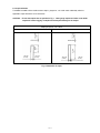
5-2. Staple Selection
The Model N 5008AC utilizes medium crown staples, gauge #16, 7/16" width crown collated by adhesive.
Applicable staple dimensions are shown below.
CAUTION: Ensure that staples are as specified in Fig. 1. Other gauge staples and other crown width
staples will cause clogging of staples and subsequent damage to the stapler.
Minimum
Staple gauge #16, 7/16" crown
Fig. 1 Dimensions of staple
Maximum
7.85 mm
(0.309")
1.45 mm
(0.057")
1.61 mm
(0.063")
25 mm
(1")
7.85 mm
(0.309")
1.45 mm
(0.057")
1.61 mm
(0.063")
51 mm
(2")

--- 4 ---
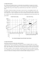
5-3. Staple Driving Force
Fig. 2 shows by type of wood and staples, the stapler output energy provided by the supply pressure and the
stapling energy required for driving the staple flush. Air pressure which exceeds the intersecting point between
the stapler output energy and the stapling energy required for driving the staple allows the staple to be fully
driven.
For example, when driving a staple of 50 mm length (2") into five sheets of 12 mm plywood (60 mm thick ) with
the Model N 5008AC, a pressure of about 6.2 bar (6.3 kgf/cm
2
, 90 psi) allows the stapler to drive the staple flush
with the wood surface. A pressure beyond this value causes the staple head to be driven below the wood surface.
Fig. 2 should be used as reference data because those values vary depending on the type, moisture content, and
grain of wood.
Fig. 2 Required stapling energy and stapler output energy
P
U
Y
1200
1200
Required stapling energy
N 5008AC, R
Stapler output energy
5-4. Optional Accessories
Sequential trip mechanism kit (Single shot) (Code No. 876762)
A sequential trip mechanism kit is provided as an optional accessory for the Model N 5008AC. By using this
optional accessory, a staple is driven by pressing the pushing lever first against a workpiece and then pulling the
trigger (single-shot operation), and no staple is driven when pulling the trigger first and then pressing the pushing
lever against a workpiece. Please recommend the sequential trip mechanism kit to the customers who want to
use it. Salespersons must instruct the customers to read the Handling Instructions attached to the sequential trip
mechanism kit and also the Handling Instructions of the Model N 5008AC thoroughly for correct use.
Staple length mm (in)

--- 5 ---
Driving depth
adjustment mechanism
With wrench
None
With wrench
With wrench
Single-touch
operation by hand
Single-touch
operation by hand
6. COMPARISONS WITH SIMILAR PRODUCTS
Maker
HITACHI
Air consumption at
7 kgf/cm
2
(100 psi)
Operating pressure
Jam-release
Weight
Dimensions
(L x H x W)
Model name
Staple capacity (Max.)
5 --- 8.5 kgf/cm
2
(70 --- 120 psi)
365 mm x 254 mm x 76 mm
(14-3/8" x 10" x 3")
N 5008AC
1.14 ltr./cycle
(.040 ft
3
/cycle)
160
Single-touch
operation by hand
2.0 kgf (4.4 lbs.)
5 --- 8.5 kgf/cm
2
(70 --- 120 psi)
367 mm x 245 mm x 70 mm
(14-3/8" x 9-5/8" x 2-3/4")
N 5008AB
1.24 ltr./cycle
(.044 ft
3
/cycle)
163
2.5 kgf (5.5 lbs.)
5.6 --- 8.4 kgf/cm
2
(80 --- 120 psi)
356 mm x 248 mm x 76 mm
(14" x 9-3/4" x 3")
1.06 ltr./cycle
(.037 ft
3
/cycle)
150
1.9 kgf (4.1 lbs.)
R
4.6 --- 8.4 kgf/cm
2
(65 --- 120 psi)
360 mm x 245 mm x 70 mm
(14-3/16" x 9-5/8" x 2-3/4")
1.17 ltr./cycle
(.041 ft
3
/cycle)
150
2.2 kgf (4.9 lbs.)
Y
5 --- 8.5 kgf/cm
2
(70 --- 120 psi)
370 mm x 285 mm x 90 mm
(14-1/8" x 11-1/8" x 3-1/2")
1.63 ltr./cycle
(.058 ft
3
/cycle)
160
2.4 kgf (5.3 lbs.)
U
5 --- 7.1 kgf/cm
2
(70 --- 100 psi)
365 mm x 285 mm x 76 mm
(14" x 11-1/8" x 3")
0.98 ltr./cycle
(.035 ft
3
/cycle)
160
2.4 kgf (5.3 lbs.)
P
Single-touch
operation by hand
Single-touch
operation by hand
Single-touch
operation by hand
Single-touch
operation by hand
With tool
*Driving speed
(staples/sec.) (Max.)
12.7
10.0
11.4
11.2
9.7
Applicable
staples
#16 gauge
wire
Length
Inside width
25 mm -- 50 mm
(1" -- 2")
7.85 mm (.309")
7.85 mm (.309")
Outside width
7/16"
25 mm -- 50 mm
(1" -- 2")
25 mm -- 50 mm
(1" -- 2")
25 mm -- 50 mm
(1" -- 2")
25 mm -- 55 mm
(1" -- 2-1/8")
19 mm -- 50 mm
(3/4" -- 2")
7.95 mm (.313") 9.8 mm (.386")
7.95 mm (.313")
9.5 mm (.374")
7/16"
7/16"
7/16"
1/2"
1/2"
* The driving speeds shown above are the result of measurement using special experimental instruments. Note that the actual dr
iving speed varies depending on the
specifications of the compressor and the air hose and the conditions of the workpiece. Exercise extra care for safety when p
erforming quick driving using the stapler
.

--- 6 ---
7. PRECAUTIONS IN SALES PROMOTION
In the interest of promoting the safest and most efficient use of the Model N 5008AC Stapler by all of our
customers, it is very important that at the time of sale the salesperson carefully ensures that the buyer seriously
recognizes the importance of the contents of the Instruction Manual, and fully understands the meaning of the
precautions listed on the Warning Label attached to each tool.
The Model N 5008AC Stapler is designed for continuous staple driving. At time of sale, the salesperson must
inform the customer that the sequential trip mechanism kit which can change the Model N 5008AC to a single-
shot stapler is optionally available, and recommend it to the customers who want to use it. Refer to the leaflet
attached together with the Instruction Manual for details.
7-1. Instruction Manual
Although every effort is made in each step of design, manufacture, and inspection to provide protection against
safety hazards, the dangers inherent in the use of any pneumatic tool cannot be completely eliminated.
Accordingly, general precautions and suggestions for use of pneumatic tools, and specific precautions and
suggestions for the use of the pneumatic stapler are listed in the Instruction Manual to enhance the safe, efficient
use of the tool by the customer.
Salespersons must be thoroughly familiar with the contents of the Instruction Manual to be able to offer
appropriate guidance to the customers during sales promotion.
7-2. Warning Label
Each Model N 5008AC unit is provided with a Warning Label (illustrated below) which lists basic safety
precautions in its use. Carefully ensure that customers fully understand and follow these precautions before using
the tool.

--- 7 ---
7-3. Related Laws and Regulations
As nailers and staplers are designed to instantaneously drive nails and staples, there is an ever-present danger of
misfiring and subsequent possible serious injury. Accordingly, close attention in handling is absolutely necessary
at all times. Carefully ensure that the customer is fully aware of the precautions listed in the Instruction Manual
provided with each unit.
While there are no specific safety regulations, there are related items in various general safety regulations with
which the salespersons should be familiar in order to properly advise the customer. Please check your national
and/or local regulations for applicable items. Some applicable items are outlined below.
The U.S.A:
OSHA 1926.102 Eye and face protection
1926.302 Power-operated hand tools
ANSI SNT-101-1993 Portable, Compressed-Air-Actuated,
Fastener Driving Tools-Safety Requirements for

--- 8 ---
8. MECHANISM AND OPERATION PRINCIPLE
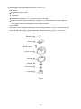
8-1. Mechanism
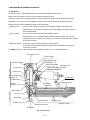
As illustrated in Fig. 3, the Model N 5008AC can be generally divided into four sections:
output section, control valve section, driving section and magazine section.
The driving section (nose and piston) and the magazine section have been newly designed though its basic
construction is the same as that of the Model NT 65A2 (valve section is common to the Model NT 65A2).
Primary differences from the Model NT 65A2 are described below.
Output section
........
The piston (driver blade) has been newly designed according to the shape of the
staple firing gate. Owing to the enlargement of the driver blade, the piston bumper has
been newly designed.
Driving section
........
All the parts have been newly designed for driving staples.
A pushing lever piece is provided to adjust the driving depth of staples with a wrench.
If clogged staples are caused in this section, they can be easily released simply by pulling
the lock lever by hand.
Magazine section
....
All the parts have been newly designed for driving staples.
The magazine cover is opened by pulling the staple feeder backward for easy loading or
replacement of staples.
The <Bold> numbers in the figure below correspond to the numbers in "8-2. Operation Principle".
Fig. 3 Construction
Exhaust Vent < 3 >
Return Air
Chamber < 8 >
Driver Blade < 7 >
Cylinder < 6 >
Piston < 4 >
Piston
Bumper < 9 >
Nose <10>
Blade Guide
Pushing Lever
Accumulator < 1 >
Control valve
section
Exhaust Cover
Cylinder Spring <5>
Trigger Valve portion
Grip Rubber
Staple Rail
Magazine Ass'y
Staple Feeder
Magazine section
Safety Valve portion
Driving section Output section
Exhaust Valve < 2 >
Lock Lever
Pushing Lever Piece
Firing Gate
Handle Arm
Magazine Cover

--- 9 ---
8-2. Operation Principle
The operation of the Model N 5008AC is illustrated and described in Fig. 4 through 7. The circled numbers in the
descriptions correspond to the item numbers shown in the mechanism illustrated in Fig. 3. In Fig. 5 and Fig. 7,
read the descriptions in alphabetical order.
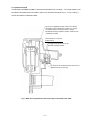
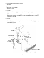
Fig. 4 When the compressed air source (air hose) is connected to the nailer
Air pressure is applied to the lower surface of the flanges
located at the center portion of the Cylinder < 6 >, forcing
the cylinder upward. The compressed air is thereby
blocked from the upper end of the cylinder, and no pressure
is applied to the piston.
The Accumlator < 1 > fills with
compressed air.
The trigger and pushing lever are not
operated, and remain closed.
The exhaust vents are opened and no air pressure is
applied to the valve air passage.

--- 10 ---
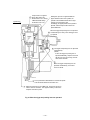
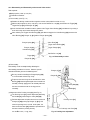
Fig. 5 When the trigger and pushing lever are operated
Although air pressure is applied to both the
upper and lower sides of the cylinder, the
cylinder is forced downward due to the larger
effective area of the upper side.
Accordingly, the upper portion of the cylinder is
opened, and the compressed air forces the
piston downward.
When the trigger and pushing lever are operated
simultaneously, the safety valve and trigger valve
are opened.
The trigger and pushing lever are operated
simultaneously.
(NOTE)
If either the trigger or pushing lever is
operated individually, compressed air will
not enter the valve air passage, and the
nailer will not function.
When the trigger and pushing lever are
operated simultaneously, the exhaust
vents are closed.
Compressed air is applied
to the upper side of the
Exhaust Valve < 2 >, forcing
it downward and closing
the Exhaust Vent < 3 >.
As the piston moves downward, the air below the piston
is forced into the Return Air Chamber < 8 >.
When the piston passes the middle vent, some of the air passes
into the return air chamber. This supplies auxiliary air to ensure
complete return of the piston.
Cylinder ring

--- 11 ---
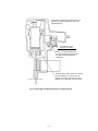
Fig. 6 If the trigger and the pushing lever are kept pressed
Air pressure is applied in the shaded areas in the
illustration, and each component is held in the
position illustrated.
The lower surface of the Piston < 4 > contacts
the Piston Bumper < 9 > and prevents air
leakage. If the upper surface of the Piston
Bumper < 9 > is damaged, some air will leak.
At there is no o-ring installed here, a
very small amount of air will leak from
the slight clearance between the
components.
If the operator's grip is
loosened, air will leak.

--- 12 ---
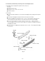
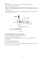
Fig. 7 When the trigger and/or the pushing lever are released
The air pressure on the upper surface of the Exhaust Valve < 2 > is
released, and the exhaust valve is pushed upward by the air pressure
within the cylinder. This opens the Exhaust Vent < 3 >, and the air
pressure in the cylinder is discharged from the nailer.
Air pressure is discharged from the upper end of
the cylinder, and the cylinder is pushed upward by
the air pressure on the lower surfaces of the
flanges and the force of the Cylinder Spring < 5 >.
This closes the upper end of the cylinder, and
blocks compressed air from entering the cylinder.
At the time the piston returns, any remaining air pressure at the lower
end of the piston is discharged through the clearance between the
Piston Bumper < 9 > and the Driver Blade < 7 >.
When the air pressure at the upper side
of the piston lowers, the air pressure
within the Return Air Chamber < 8 >
pushes the piston upward.
(NOTE) If the clearance were larger, the
piston would not return: if it were
smaller, driving force would be
decreased.
When the trigger is released, the trigger valve closes
and the air pressure within the valve air passage is
discharged through Valve Exhaust Vent I .
In addition, when the pushing lever is lifted from
the wood surface, the safety valve closes, and
the air pressure within the valve air passage is
discharged through Valve Exhaust Vent II .
(The illustration shows both the trigger and
pushing lever released.)
Valve Exhaust Vent II
Valve Exhaust Vent I

--- 13 ---
<Magazine>
Staple feeder abnormal
(burrs, deformed,
damaged).
<Staples>
The magazine is not loaded
with specified genuine
staples.
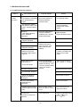
Problem
Possible cause
( : most-common cause)
Inspection method Remedy
Correct the burred or
deformed portion.
Replace the defective part.
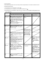
9. TROUBLESHOOTING GUIDE
9-1. Troubleshooting and Correction
1) Staples
cannot
be driven.
Check if the magazine is
normally loaded with
specified staples.
Check if they move
smoothly after putting
staples and check if the
staple feeder operates
smoothly.
Check the staple feeding
section for abnormal
conditions (burrs, fatigued,
deformed, damaged).
Check if staples can be
driven at 5 kgf/cm
2
(
4.9 bar,
70 psi
).
Use specified staples.
After removing the adhesive
fragments and wood chips,
apply oil to the staple
feeder.
The magazine is loaded
with abnormal staples (bent
staples, abnormal collation,
other).
Remove the abnormal
staples and load the
magazine with normal
staples.
Ribbon spring abnormal
(fatigued, damaged).
Staple rail width too wide.
Magazine cover abnormal
(deformed, damaged).
Adhesive fragments and
wood chips are on the
magazine, staple feeder or
staple rail.
Replace the defective part.
Replace the defective part.
Replace the defective part.
Cylinder's internal surface
abnormal (deposites of dirt,
worn).
Driver blade abnormal
(deformed, burrs,
damaged).
Cylinder ring abnormal.
(dislocated, deformed,
damaged).
Piston bumper abnormal.
Replace the piston bumper.
Reassemble or replace.
Touch up or replace.
After removing the dirt,
apply oil or replace.
Piston O-ring worn.
Air pressure too low.
Keep the staple feeder
ass'y pulling backward and
perform idle driving. Then
check that the driver blade
returns to its original
position.
Adjust for 5 to 8.5 kgf/cm
2
(4.9 --- 8.3 bar, 7 --- 120 psi).
<Output section: Piston,
driver blade, etc.
>
Replace the piston O-ring.
Pushing lever incorrectly
adjusted.
Check adjustment.
Adjust the protruded amount
within 4.5 0.5 mm
(0.177" 0.02").
<Pushing lever>

--- 14 ---
< Improper staple feed >
See <Magazine> in item 1).
Driver blade worn.
< The driver blade has not
returned completely.
>
See <Output section:
Piston, driver blade, etc.>
in item 1).
Staples are not fully fed into
the injection port.
Unspecified staples used.
Driver blade worn.
The material being driven
into is very hard.
Air pressure too low.
The material being driven
into is very hard.
Driver blade worn.
Piston O-ring abnormal
(worn, damaged).
Cylinder's internal surface
abnormal (worn, rough).
Unspecified staples used.
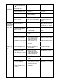
Problem
Possible cause
( : most-common cause)
Inspection method Remedy
2) Staples bent
while being
driven.
See item 1).
See item 1).
Check if the driver blade tip
is abnormally worn.
Check if a staple is bent
even when driven into soft
wood.
See item 1).
See item 1).
Replace the part.
Unusable because the tool
is not designed for such
usage.
Adjust for 5 to 8.5 kgf/cm
2
(4.9 --- 8.3 bar, 70 --- 120 psi)
.
Unusable because the tool
is not designed for such
usage.
Replace the part.
Replace the defective part.
Replace the defective part.
Use specified staples.
See <Magazine> in item 1).
Replace the part.
See <Output section: Piston,
driver blade, etc.> in item 1).
3) The staple is
driven into the
material but
the head is
raised above
the surface.
Drive the staple into soft
wood and check if the head
is raised or not.
Check if the driver blade tip
is worn.
Disassemble the output
section and check the
piston O-ring and the
internal surface of the
cylinder for abnormal
condition.
Check if the staples are
specified ones.
Check if they move
smoothly after putting
staples, and check if the
staple feeder operates
smoothly.
Check if the driver blade tip
is worn.
Perform idle driving or
actually drive with staples,
and check if the driver
blade has returned
completely.
4) Staples clog
the
mechanism.

--- 15 ---
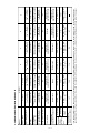
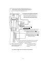
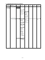
9-2. Possible Causes and Corrections of Air Leakage
Air leakage repair location
A
B
C
G
D
E
F

--- 16 ---
Cylinder [13] does not return.
Swollen Cylinder O-ring (D) [11] (Use of
unsuitable oil causes swelling. Advise the
customer to use Shell Tonna Oil T32.)
Deformed Cylinder [13] or Cylinder Guide [17].
Yielded or broken Cylinder Spring [15].
Defective Head Cap [7] (worn rubber portion
or broken)
Broken Gaskets (C) [5]
Loose Hex. Socket Hd. Bolt M5 x 20 [1]
Broken Exhaust Cover [3]
Loose Hex. Socket Hd. Bolt M5 x 20 [1]
Broken Gasket (B) [4]
Damaged seal surfaces of Body [20] and
Exhaust Cover [3]
Damaged Cylinder O-ring (B) [18] or O-ring
of Cylinder Guide [17] (worn, deformed or
broken)
Defective Body [20] (worn, corroded or
deformed)
Defective Urethane Ball (C) D7.14 [47]
(damaged or deformed)
Defective ball sheet surface of Trigger Valve
Bushing [49] (damaged, deformed or worn)
Defective Valve Packing [46] (damaged,
deformed or broken)
Soiled or damaged valve packing sheet
surface of Body [20]
Incursion of foreign materials
Defective Gaskets (B) (C) [4] [5] (damaged or
yielded)
Discorded air vent of Gasket (B) [4]
Defective O-ring (S-65) [10] or Cylinder
O-ring (D) [11] of the Cylinder Plate [12]
(worn, deformed or broken)
Defective Cylinder O-ring (D) [11] (worn,
deformed or broken)
Loose Hex. Socket Hd. Bolt M5 x 16 [35]
Broken Gasket (D) [33]
Defective seal surface of the Body [20] or
Cap [34]
Defective Exhaust Valve
[6] (worn, deformed, or
broken)
Exhaust vent
Air leak part
Cause
When trigger valve/safety valve are OFF
When trigger valve/
safety valve are ON
Inspection priorities:
In the table below, possible causes of air leakage and their repair procedures are marked in accordance with the
likelihood of possible failure.
(1) First priority items are marked with an asterisk ( ).
(2) Second priority items (seal portions) are marked with a double circle ( ).
(3) Remaining items are marked with a single circle ( ). (See Parts List and exploded assembly diagram for part
name and location.)
Deformed Nose [25]
Loose Nylock Hex. Socket
Hd. Bolt M5 x 16 [26]
When trigger valve ON/
safety valve OFF
A
Exhaust cover
B
Nose
C
Nose
D
Trigger valve
E
Safety valve
F
Cap
G
Air will leak slightly from
the lower portion due to
construction.
Defective Plunger O-ring
[42] (worn, deformed or
broken)
Defective outside
O-ring (S-12) [43] of
Trigger Valve Bushing
[49]
Broken or cracked
Piston Bumper [22]
Deformed Piston [9]
Deformed Nose [25]
Defective outside O-ring
(S-12) [43] of the Valve
Bushing [44] (worn,
deformed or broken)
Defective Plunger O-ring
[42] (worn, deformed or
broken)
Defective Plunger Spring
[40] (deformed or broken)
Defective safety Valve
Bushing [44] (deflected,
deformed or broken)

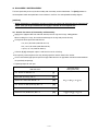
--- 17 ---
10. DISASSEMBLY AND REASSEMBLY
The items particularly necessary for disassembly and reassembly are described below. The [Bold] numbers in
the descriptions below correspond to the item numbers in the Parts List and exploded assembly diagram.
[CAUTION]
Before disassembly or reassembly, be sure to remove all staples and disconnect the air hose from the
stapler (with your finger released from the trigger) to exhaust all the compressed air.
10-1. General Precautions in Disassembly and Reassembly
Apply grease (Nippeco SEP-3A, Code No. 930035) to the O-rings and O-rings' sliding portions.
When installing the O-rings, be careful not to damage the O-rings and prevent dirt entry.
Oil required: Hitachi pneumatic tool lubricant
1 oz (30 cc) oil feeder (Code No. 877153)
4 oz (120 cc) oil feeder (Code No. 874042)
1 quart (1 ltr) can (Code No. 876212)
If Gasket (B) [4] is damaged, replace it and check that no air is leaking.
Be especially careful to prevent the entry of foreign particles into the control valve section.
Use the conventional grip tape for repair of the grip rubber because the grip rubber cannot be mounted without
the specifically designed jig.
Tightening torque for each part
Bolt and screw
Tightening torque
N
•
m (kgf
•
cm, ft-lb.)
Hex. Socket Hd. Bolt M5 x 20 ....................................... [1]
8.3 0.5 (85 5, 6.1 0.4)
Nylock Hex. Socket Hd. Bolt M5 x 16 ........................... [26]
Nylock Bolt (W/Flange) M5 x 8 ..................................... [54]
Hex. Socket Hd. Bolt (W/Flange) M5 x 16 .................... [39]
Machine Screw (W/Washers) M5 x 14 .......................... [69]
Hex. Socket Hd. Bolt M5 x 16 ....................................... [35]
1.9 0.5 (20 5, 1.4 0.4)
Page is loading ...
Page is loading ...
Page is loading ...
Page is loading ...
Page is loading ...
Page is loading ...
Page is loading ...
Page is loading ...
Page is loading ...
Page is loading ...
Page is loading ...
Page is loading ...
Page is loading ...
-
 1
1
-
 2
2
-
 3
3
-
 4
4
-
 5
5
-
 6
6
-
 7
7
-
 8
8
-
 9
9
-
 10
10
-
 11
11
-
 12
12
-
 13
13
-
 14
14
-
 15
15
-
 16
16
-
 17
17
-
 18
18
-
 19
19
-
 20
20
-
 21
21
-
 22
22
-
 23
23
-
 24
24
-
 25
25
-
 26
26
-
 27
27
-
 28
28
-
 29
29
-
 30
30
-
 31
31
-
 32
32
-
 33
33


Hitachi N 5008AC Technical And Service Manual
- Type
- Technical And Service Manual
Ask a question and I''ll find the answer in the document
Finding information in a document is now easier with AI
Related papers
-
Hitachi N 5024A Technical Data And Service Manual
-
-
-
-
-
-
-
-
-
Other documents
-
Rapid 10290517 Datasheet
-
VENOM Atomik Gas Engine Clutch for Atomik 58in Gas RC Boats Owner's manual
-
-
Rexel 2100922 Datasheet
-
Woodstock SHOP FOX W1779 User manual
-
-
Hikoki N5008AC2 User manual
-
ROOMS TO GO 33023273 Assembly Instructions
-
Grizzly T26416 User manual
-
Vertex VA0261 Service And Repair Instructions