Page is loading ...

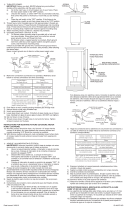
RIGID STEM MOUNT INSTALLATION
1) Passwirethroughstemandscrewstemintocouplingontopofxture
body. NOTE: Thread locking compound must be applied to all stem
threads as noted with symbol (3) to prevent accidental rotation of
xtureduringcleaning,relamping,etc.
2) Passxturewirethroughremainingstemsandscrewstemstogether.
3) Screw short threaded pipe into top of stem.
4) Pass hole in canopy over end of threaded pipe on top of stem.
5) Sliplockwasheroverendofthreadedpipeandscrewhexnutontoend
ofthreadedpipe.Tightenhexnuttosecurecanopytoxture.
6) TURN OFF POWER.
IMPORTANT:Beforeyoustart,NEVERattemptanyworkwithout
shutting off the electricity until the work is done.
a) Gotothemainfuse,orcircuitbreaker,boxinyourhome.Place
the main power switch in the “OFF” position.
b) Unscrewthefuse(s),orswitch“OFF”thecircuitbreakerswitch(s),
thatcontrolthepowertothextureorroomthatyouareworkingon.
c) Placethewallswitchinthe“OFF”position.Ifthexturetobe
replacedhasaswitchorpullchain,placethoseinthe“OFF”
position.
7) Find the appropriate threaded holes on mounting strap. Assemble
mounting screws into threaded holes.
8) Attachmountingstraptooutletbox.(Screwsnotprovided).Mounting
strapcanbeadjustedtosuitpositionofxture.
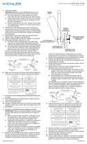
9) Grounding instructions: (See Illus. A or B).
A) Onxtureswheremountingstrapisprovidedwithaholeandtwo
raiseddimples.Wrapgroundwirefromoutletboxaroundgreen
groundscrew,andthreadintohole.
B) Onxtureswhereacuppedwasherisprovided.Attachground
wirefromoutletboxundercuppedwasherandgreenground
screw,andthreadintomountingstrap.
Ifxtureisprovidedwithgroundwire.Connectxturegroundwireto
outletboxgroundwirewithwireconnector(notprovided.)afterfollowing
the above steps. Never connect ground wire to black or white power
supply wires.
10)Makewireconnections(connectorsnotprovided).Referencechart
below for correct connections and wire accordingly.
11) Pushxturetoceiling,carefullypassingmountingscrewsthroughholes
in canopy.
12)Securexturetoceilingwiththreadedballs.
13) Lower inner glass down over socket.
14) Lower outer glass down over inner glass.
15) Insert recommended bulb.
INSTALACIÓN DE MONTAJE RÍGIDO MADRE
1) Pase el alambre del artefacto a través del vástago y atornille el vástago
al tope del artefacto. IMPORTANTE: Por lo menos uno 6” vástago debe
ser utilizado. NOTA: El compuesto para rosca estanca se debe
aplicar a todas las roscas del vástago como se notó con el símbolo (3)
paraimpedirlarotaciónaccidentaldelartefactodurantelalimpieza,
instalacióndeunabombillanueva,etc.
2) Pase el alambre del artefacto a través de los vástagos restantes y atornille
los vástagos juntos.
3) Atornille el tubo roscado corto en el tope de vástago.
4) Pasedelagujeroenelescudeteencimadelextremodeltuboroscado
encima de vástago.
5) Resbale la arandela de seguridad encima del tubo roscado que sobresale
deadentrodelcapuchón.Atornillelatuercahexagonalaltuboroscado.
6) APAGUELAALIMENTACIÓNELÉCTRICA.
IMPORTANTE: Antesdecomenzar,NUNCAtratedetrabajarsinantes
desconectar la corriente hasta que el trabajo se termine.
a) Vayaalacajaprincipaldefusibles,ointerruptorocajadecircuitos
desucasa.Coloqueelinterruptordelacorrienteprincipalen
posición de apagado “OFF”.
b) Desatornilleel(los)fusible(s),ocoloqueelinterruptorointerruptores
delbreakerenposicióndeapagado“OFF”,quecontrola(n)la
corriente hacia el artefacto o habitación donde está trabajando.
c) Coloqueelinterruptordeparedenposicióndeapagado“OFF”.Si
el artefacto que se va a reemplazar tiene un interruptor o cadena
quesejala,colóquelosenlaposicióndeapagado“OFF”.
7) Encontrar los agujeros roscados correctos en la abrazadera de
montaje. Instalar los tornillos de montaje en los agujeros roscados.
8) Unirlaabrazaderademontajealacajadeconexiones.(Noseproveen
tornillos). La abrazadera de montaje puede ajustarse para acomodar la
posición del artefacto.
9) InstruccionesdeconexiónatierrasolamenteparalosEstados
Unidos.(VealailustracionAoB).
A) Enlaslámparasquetieneneleje,demontajeconunagujeroy
dos hoyue los realzados. Enrollar el alambre a tierra de la caja
tomacorriente alrededor del tornillo verde y pasarlo por el aquiero.
B) En las lámparas con una arandela acopada. Fijar el alambre a
tierra de la caja tomacorriente del ajo de la arandela acoada y
tornilloverde,ypaserporelejedemontaje.
Silalámparavieneconalambreatierra.Conecterelalambreatierra
de la lámpara al alambre a tierra de la caja tomacorriente con un conector
de alambres (no incluido) espués de seguir los pasos anteriores. Nunca
conectar el alambra a tierra a los alambres eléctros negro o blanco.
10)Hagalesconexionesdelosalambres(noseproveenlosconnectores.)
Latabladereferenciadeabajoindicalasconexionescorrectasylos
alambres correspondientes.
11) Empujeelartefactohaciaeltecho,pasandocuidadosamentelos
tornillosdemontajeatravésdelosoriciosenelescudete.
12) Sujete el artefacto contra el cielorraso con las bolas roscadas.
13) Bajar el interior de vidrio hacia abajo sobre el casquillo.
14)Bajarelvidrioexteriorhaciaabajosobreelinteriordevidrio.
15) Inserte el bombilla recomendado.
Connect Black or
Red Supply Wire to:
Connect
White Supply Wire to:
Black White
*Parallel cord (round & smooth) *Parallel cord (square & ridged)
Clear, Brown, Gold or Black
without tracer
Clear, Brown, Gold or Black
with tracer
Insulated wire (other than green)
with copper conductor
Insulated wire (other than green)
with silver conductor
*Note: When parallel wires (SPT I & SPT II)
are used. The neutral wire is square shaped
or ridged and the other wire will be round in
shape or smooth (see illus.)
Neutral Wire
Conectar el alambre de
suministro negro o rojo al
Conectar el alambre de
suministro blanco al
Negro Blanco
*Cordon paralelo (redondo y liso)
*Cordon paralelo (cuadrado y estriado)
Claro, marrón, amarillio o negro
sin hebra identificadora
Claro, marrón, amarillio o negro
con hebra identificadora
Alambre aislado (diferente del verde)
con conductor de cobre
Alambre aislado (diferente del
verde) con conductor de plata
*Nota: Cuando se utiliza alambre paralelo
(SPT I y SPT II). El alambre neutro es de forma
cuadrada o estriada y el otro alambre será de
forma redonda o lisa. (Vea la ilustracíón).
Hilo Neutral
Date Issued: 3/9/12 IS-42549-US
GREEN GROUND
SCREW
CUPPED
WASHER
A
B
OUTLET BOX
GROUND
FIXTURE
GROUND
DIMPLES
WIRE CONNECTOR
(NOT PROVIDED)
OUTLET BOX
GROUND
GREEN GROUND
SCREW
FIXTURE
GROUND
ARANDELA
CONCAVA
A
B
TIERRA DE LA
CAJA DE SALIDA
TORNILLO DE TIERRA,
VERDE
DEPRESIONES
TIERRA
ARTEFACTO
CONECTOR DE ALAMBRE
(NO SE PROVEE)
TIERRA DE LA
CAJA DE SALIDA
TORNILLO DE TIERRA,
VERDE
TIERRA
ARTEFACTO
THREADED BALL
BOLAROSCADO
CANOPY
ESCUDETE
STEM
VÁSTAGO
RIGID STEM MOUNT
MONTAJE DEL RÍGIDO MADRE
MOUNTINGSTRAP
PLANCHAPARAMONTAR
4
SEE OTHER SIDE FOR LOOP/CHAIN LINK
MOUNT INSTALLATION.
VEA EL OTRO LADO PARA LA INSTALACIÓN
DEL ESLABÓN DE CADENA / LAZO
OUTER GLASS
VIDRIO
EXTERIOR
4
4
INNER GLASS
VIDRIO
INTERIOR
BULB
BOMBILLA

10)Unirlaabrazaderademontajealacajadeconexiones.(Noseproveen
tornillos). La abrazadera de montaje puede ajustarse para acomodar la
posición del artefacto.
11) InstruccionesdeconexiónatierrasolamenteparalosEstados
Unidos.(VealailustracionAoB).
A) Enlaslámparasquetieneneleje,demontajeconunagujeroy
dos hoyue los realzados. Enrollar el alambre a tierra de la caja
tomacorriente alrededor del tornillo verde y pasarlo por el aquiero.
B) En las lámparas con una arandela acopada. Fijar el alambre a
tierra de la caja tomacorriente del ajo de la arandela acoada y
tornilloverde,ypaserporelejedemontaje.
Silalámparavieneconalambreatierra.Conecterelalambreatierra
de la lámpara al alambre a tierra de la caja tomacorriente con un
conector de alambres (no incluido) espués de seguir los pasos
anteriores. Nunca conectar el alambra a tierra a los alambres eléctros
negro o blanco.
12)Hagalesconexionesdelosalambres(noseproveenlosconnectores.)
Latabladereferenciadeabajoindicalasconexionescorrectasylos
alambres correspondientes.
13)Empujeelartefactohaciaeltecho,pasandocuidadosamentelos
tornillosdemontajeatravésdelosoriciosenelescudete.
14) Sujete el artefacto contra el cielorraso con las bolas roscadas.
15) Bajar el interior de vidrio hacia abajo sobre el casquillo.
16)Bajarelvidrioexteriorhaciaabajosobreelinteriordevidrio.
17) Inserte el bombilla recomendado.
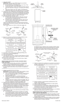
LOOP/CHAIN LINK MOUNT INSTALLATION
1) Passwirethroughstemandscrewstemintocouplingontopofxture
body. NOTE: Thread locking compound must be applied to all stem
threads as noted with symbol (3) to prevent accidental rotation of
xtureduringcleaning,relamping,etc.
2) Passxturewirethroughremainingstemsandscrewstemstogether.
3) Screw threaded pipe into end of each loop.
4) Screw small loop on to top of stem.
5) Pass threaded pipe at end of second small loop through hole in canopy.
6) Slip lockwasher over threaded pipe protruding from inside of canopy
andscrewhexnutontothreadedpipe.
7 ) Attach chain link to small loop at end of stem and to loop on canopy.
8) TURN OFF POWER.
IMPORTANT:Beforeyoustart,NEVERattemptanyworkwithout
shutting off the electricity until the work is done.
a) Gotothemainfuse,orcircuitbreaker,boxinyourhome.Place
the main power switch in the “OFF” position.
b) Unscrewthefuse(s),orswitch“OFF”thecircuitbreakerswitch(s),
thatcontrolthepowertothextureorroomthatyouareworkingon.
c) Placethewallswitchinthe“OFF”position.Ifthexturetobe
replacedhasaswitchorpullchain,placethoseinthe“OFF”
position.
9) Find the appropriate threaded holes on mounting strap. Assemble
mounting screws into threaded holes.
10)Attachmountingstraptooutletbox.(Screwsnotprovided).Mounting
strapcanbeadjustedtosuitpositionofxture.
11) Grounding instructions: (See Illus. A or B).
A) Onxtureswheremountingstrapisprovidedwithaholeandtwo
raiseddimples.Wrapgroundwirefromoutletboxaroundgreen
groundscrew,andthreadintohole.
B) Onxtureswhereacuppedwasherisprovided.Attachground
wirefromoutletboxundercuppedwasherandgreenground
screw,andthreadintomountingstrap.
Ifxtureisprovidedwithgroundwire.Connectxturegroundwireto
outletboxgroundwirewithwireconnector(notprovided.)afterfollowing
the above steps. Never connect ground wire to black or white power
supply wires.
12)Makewireconnections(connectorsnotprovided).Referencechart
below for correct connections and wire accordingly.
13)Pushxturetoceiling,carefullypassingmountingscrewsthroughholes
in canopy.
14)Securexturetoceilingwiththreadedballs.
15) Lower inner glass down over socket.
16) Lower outer glass down over inner glass.
17) Insert recommended bulb.
INSTALACIÓN DEL ESLABÓN DE CADENA / LAZO
1) Pase el alambre del artefacto a través del vástago y atornille el vástago
al tope del artefacto. IMPORTANTE: Por lo menos uno 6” vástago debe
ser utilizado. NOTA: El compuesto para rosca estanca se debe
aplicar a todas las roscas del vástago como se notó con el símbolo (3)
paraimpedirlarotaciónaccidentaldelartefactodurantelalimpieza,
instalacióndeunabombillanueva,etc.
2) Pase el alambre del artefacto a través de los vástagos restantes y atornille
los vástagos juntos.
3) Rosqueuntuboroscadopequeñoencadaunodelosextremosdelos
lazos.
4) Atornille un lazo pequeño en el tope de cada vástago.
5) Paseeltuboroscadoenelextremodelsegundolazopequeñoatravés
del agujero en el escudete.
6) Resbale la arandela de seguridad encima del tubo roscado que sobresale
deadentrodelcapuchón.Atornillelatuercahexagonalaltuboroscado.
7) Acopleuneslabóndecadenaallazopequeñoenelextremodelvástago
y al lazo en el escudete.
8) APAGUELAALIMENTACIÓNELÉCTRICA.
IMPORTANTE: Antesdecomenzar,NUNCAtratedetrabajarsinantes
desconectar la corriente hasta que el trabajo se termine.
a) Vayaalacajaprincipaldefusibles,ointerruptorocajadecircuitos
desucasa.Coloqueelinterruptordelacorrienteprincipalen
posición de apagado “OFF”.
b) Desatornilleel(los)fusible(s),ocoloqueelinterruptorointerruptores
delbreakerenposicióndeapagado“OFF”,quecontrola(n)la
corriente hacia el artefacto o habitación donde está trabajando.
c) Coloqueelinterruptordeparedenposicióndeapagado“OFF”.Si
el artefacto que se va a reemplazar tiene un interruptor o cadena
quesejala,colóquelosenlaposicióndeapagado“OFF”.
9) Encontrar los agujeros roscados correctos en la abrazadera de
montaje. Instalar los tornillos de montaje en los agujeros roscados.
Connect Black or
Red Supply Wire to:
Connect
White Supply Wire to:
Black White
*Parallel cord (round & smooth)
*Parallel cord (square & ridged)
Clear, Brown, Gold or Black
without tracer
Clear, Brown, Gold or Black
with tracer
Insulated wire (other than green)
with copper conductor
Insulated wire (other than green)
with silver conductor
*Note: When parallel wires (SPT I & SPT II)
are used. The neutral wire is square shaped
or ridged and the other wire will be round in
shape or smooth (see illus.)
Neutral Wire
Conectar el alambre de
suministro negro o rojo al
Conectar el alambre de
suministro blanco al
Negro Blanco
*Cordon paralelo (redondo y liso)
*Cordon paralelo (cuadrado y estriado)
Claro, marrón, amarillio o negro
sin hebra identificadora
Claro, marrón, amarillio o negro
con hebra identificadora
Alambre aislado (diferente del verde)
con conductor de cobre
Alambre aislado (diferente del
verde) con conductor de plata
*Nota: Cuando se utiliza alambre paralelo
(SPT I y SPT II). El alambre neutro es de forma
cuadrada o estriada y el otro alambre será de
forma redonda o lisa. (Vea la ilustracíón).
Hilo Neutral
GREEN GROUND
SCREW
CUPPED
WASHER
A
B
OUTLET BOX
GROUND
FIXTURE
GROUND
DIMPLES
WIRE CONNECTOR
(NOT PROVIDED)
OUTLET BOX
GROUND
GREEN GROUND
SCREW
FIXTURE
GROUND
ARANDELA
CONCAVA
A
B
TIERRA DE LA
CAJA DE SALIDA
TORNILLO DE TIERRA,
VERDE
DEPRESIONES
TIERRA
ARTEFACTO
CONECTOR DE ALAMBRE
(NO SE PROVEE)
TIERRA DE LA
CAJA DE SALIDA
TORNILLO DE TIERRA,
VERDE
TIERRA
ARTEFACTO
SEE OTHER SIDE FOR RIGID STEM MOUNT IN-
STALLATION.
VEA EL OTTRO LADO PARA LA INSTALACIÓN
DE MONTAJE RÍGIDO MADRE.
LOOP/CHAIN LINK
LAZO/ ESLABÓN DE CADENA
LOOP
ANILLO
3
3
Date Issued: 3/9/12 IS-42549-US
CANOPY
ESCUDETE
STEM
VÁSTAGO
MOUNTINGSTRAP
PLANCHAPARAMONTAR
THREADED BALL
BOLAROSCADA
OUTER GLASS
VIDRIO
EXTERIOR
INNER GLASS
VIDRIO
INTERIOR
BULB
BOMBILLA
CHAINLINK
ESLABÓNDECADENA
/