Page is loading ...

INSTRUCTION SHEET
P.O. Box 2027, Bellingham, WA 98227 U.S.A.
PHONE: (360) 734-1540 • www.southbendlathe.com
Model SB1354
Cast Iron Workbench Legs
Copyright © October, 2010 by South Bend Lathe Co.
WARNING: No portion of this manual may be reproduced without written approval.
#JB13348 Printed in Taiwan.
Cast Iron Legs w/Brass Nameplate .....................2
Material ................................................... Cast Iron
Finish ..................................................Powder Coat
Weight ..........................................110 Lbs. Per Leg
Dimensions ...........................................See Page 4
Capacity .................................. See Warning Below
Inventory
Specifications
Things You'll Need
During the assembly process you'll need the
following (not included):
For Assembly
• Twoadditionalpeople
• BenchTop
• Lower Shelf
• Cross-brace
• Bench Mounting:
—Lag Screws
5
⁄16" Dia. x Length (Bench
Thickness+
1
⁄4") ......................................... 8
—Flat Washers
5
⁄16" ........................................ 8
—Drill Bit
1
⁄4" (pilot hole) ...............................1
• Lower Shelf Mounting:
—Lag Screws
1
⁄4" Dia. Length (Shelf
Thickness) .................................................4
—Flat Washers
1
⁄4" ......................................... 4
—Drill Bit
7
⁄32" (pilot hole) .............................. 1
• Cross-BraceMounting:
—Dependentoncross-bracingused
• Toolsneededfortighteningselected
hardware
• Cardboard (or other protective material for
assembly process) larger than bench top
dimensions
Optional
• Leveling Feet
3
⁄8"-16threadpitch
• Precision Level
• ShimStock(asneeded)
• Floor Mounting Hardware (x4)
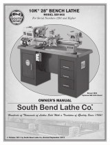
Figure 1. SB1354
(Bench top and shelf not included).
Designed with smooth flowing lines reminiscent
of industrial designs from the early 1900s, these
heavy Cast Iron Legs provide plenty of support
andstabilityforshop-madeworkbenchesor
machine stands. Just add your own bench top
and bottom shelf to suit your particular needs.
Although each leg is capable of supporting
up to 2000 lbs., the actual capacity of the
completed workbench is dependent on many
factors, including (but not limited to) material
type, quality, and dimensions of the bench
top and shelf; the method and materials used
for cross bracing; the size and quality of the
hardware used; and any forces that may be
applied to the workbench during its use.

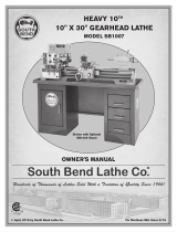
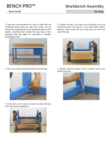
3. Place the leg in the desired position, then
markandpre-drillholesforthemounting
hardware you have chosen. Unless you
intendtodoso,takecaretoavoiddrillingall
the way through the bench top.
4. Use your chosen hardware to secure the leg
to the bench top, as shown in Figure 4.
5. Repeat Steps 2–4 for the second leg.
6. With additional people to help, carefully turn
the bench over.
7. Placeyourshelfontotheshelfbrackets,as
shown in Figure 5,thenmarkdrillholes
throughtheholesontheshelfbrackets.
Figure 4. Securing leg to bench top.
Mounting Hardware
Figure 5. Shelf placement.
Shelf
Shelf Bracket
Theprocedurethatfollowsdescribesthegeneral
steps required for assembly. Since the bench top
and shelf are not included, individual assembly
steps will vary.
Assembly
To assemble the workbench:
1. Place a piece of cardboard or other protective
material on a flat, level, hard floor, then
placeyourbenchface-downonit.
Figure 3. Leg placement.
Leg
Bench
Top
Cross-brace
Mounting Tab
The legs included in this kit weigh over 100
lbs. each. In the steps that follow, make sure
the legs are constantly stabilized to prevent
them from falling until they are secured to the
bench top in Step 4. Failure to do so could
allow the legs to fall, resulting in crushing
injuries, laceration injuries, or death.
2. With the help of one or two additional
people,placeoneofthelegsupside-down
ontotheinvertedbenchtop,makingsurethe
cross-bracemountingtabpointstowardthe
middle of the bench as shown in Figure 3.
Never attempt to weld onto the cast iron legs
or drill into them. Doing so can compromise
their strength and will void the warranty.
x 4
-2-
For Models Mfg. Since 7/10
Model SB1354
INSTRUCTIONS

8. Removetheshelf,thenpre-drillholesfor
the mounting hardware you have chosen.
Unlessyouintendtodoso,takecaretoavoid
drilling all the way through the shelf.
9. Placeyourshelfbackontotheshelfbrackets,
takingcaretolineuptheholesyoudrilledin
the previous step with the holes in the shelf
brackets.
10. Use your chosen hardware to secure the
shelftotheshelfbrackets.
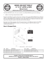
11.Installcross-bracingtoprovideadditional
stabilization between the legs, or between
thelegsandbenchtop.Twopossible
methods are shown in Figures 6–7
Thoughlevelingisnotrequired,theModel
SB1354 legs have
3
⁄8"-16pitchthreadedholesat
the base to allow for the installation of leveling
feet.
Thoughsecuringthebenchtotheoorisnot
required, the holes at the base of the legs can
be used for this purpose (to avoid interference
with the existing threads, use
5
⁄16" or smaller
hardware). Before securing the bench to the floor,
useaprecisionleveltocheckthebenchforlevel
in all directions. Place shims under the legs as
necessary until the bench is level and all four
feetareplantedrmlyontheoor.Then,use
mounting hardware to mount the bench to the
floor.
Leveling
Figure 6. Single cross brace.
Single Cross-brace
Mounting Tabs
Figure 7. Double triangle cross brace.
Double
Diagonal
Cross-braces
Mounting Tabs
Securing to Concrete
Floors
Figure 8. Common types of fasteners for securing
machinery to concrete floors.
Lag Screw
and Anchor
Anchor
Stud
Lag screws and anchors, or anchor studs
(below), are two popular methods for securing
machinery to a concrete floor. We suggest you
research the many options and methods for
securing your machine and choose the best one
for your specific application.
Anchor
Stud
Lag Screw
and Anchor
DO NOT use impact tools to secure the legs
to the floor. The impact associated with these
tools could crack the cast iron. Tighten all
floor mounting hardware by hand.
Failure to properly cross-brace the Model
SB1354 will result in a significantly reduced
maximum weight capacity and could cause
the bench to collapse under heavy vertical or
lateral loading. Collapse can result in crushing
injuries and/or property damage.
For Models Mfg. Since 7/10 Model SB1354
-3-
INSTRUCTIONS

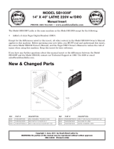
Parts*
Dimensions
1
2
3
1
2
3
36-3/8"
5/8"
2-1/4"
4-1/2"
3/4"
1-1/2"
22-1/2"
6-3/4"
2-3/4"
3/8" Dia.
Holes
5/16" Dia.
Holes
5/16" Dia.
Holes
3/8-16 TPI
Threaded Holes
REF PART # DESCRIPTION
1 PSB1354001 CAST IRON LEG
2 SB1319 SOUTH BEND NAMEPLATE
3 PS06 PHLP HD SCR 10-24 X 3/8
* Breakdown is for illustration purposes. Not all
parts may be available for purchase.
-4-
For Models Mfg. Since 7/10
Model SB1354
INSTRUCTIONS
/