

AlumiPex Radiant Tubing
Part Number 650-000-221/0298
2
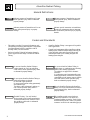
Hazard Definitions
Indicates presence of hazards that will or can
cause minor personal injury or property
damage.
Indicates special instructions on installation,
operation or maintenance that are important
but not related to personal injury or property
hazards.
Indicates presence of hazards that will cause
severe personal injury, death or substantial
property damage.
Indicates presence of hazards that can cause
severe personal injury, death or substantial
property damage.
This installation guide covers both new
construction and retrofit. For retrofit of a
completed building review the Trade Guides
with the building owner if there is no general
contractor involved in the remodeling project.
Do not use AlumiPex Radiant Tubing in
potable water or combination space heating/
potable water heating applications.
The tubing is not approved for domestic
water use.
In combination space heating/potable water
heating applications, chemical or biological
contamination in the system water is possible
and could result in severe personal injury,
death or substantial property damage.
Do not use AlumiPex Radiant Tubing to
conduct natural gas. Such an application
could result in severe personal injury, death
or substantial property damage.
Do not expose AlumiPex Radiant Tubing to
petroleum products or solvents.
Do not weld or glue AlumiPex.
Do not secure AlumiPex tubing permanently
with adhesive tape.
The tubing could be damaged, resulting in
risk of severe personal injury, death or
substantial property damage.
Codes and Standards
• This guide is provided for general information only.
The building or heating system designer is responsible
for all design details and for compliance with all
building codes, local and national.
• Refer to AlumiPex Technical Information sheets for
specific approvals and listings of AlumiPex Radiant
Tubing.
• AlumiPex Radiant Tubing is not approved for potable
water applications.
• Consult local requirements before installing a radiant
heating system. Install AlumiPex tubing following all
of the applicable codes and all specifications and
methods prescribed by the building designer and
heating system designer.
Use only AlumiPex Fittings with AlumiPex
Tubing. Use of any other method can result in
severe personal injury, death or substantial
property damage.
Finished Flooring: Use only finished
flooring rated by the flooring manufacturer
for use with heated floors. Failure to follow
this guideline could result in substantial
property damage.

Above Floor Installation Guide
Part Number 650-000-221/0298
3
Tube Layouts for Radiant Heating
Obtain Tube Layout Drawing
Meet with General Contractor
Obtain Materials
Obtain Special Equipment
Pre-Installation Check List
Mark Tube Layout on Subfloor
Mount Manifold(s)
Install the Tubing
Before Leaving the Jobsite . . .
Inspect Tubing Before Flooring Inst.
Pressurize Tubing for Observation
Pressure Test Tubing
Connect System Piping
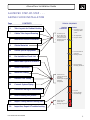
TYPICAL SEQUENCE
!
!
Site Preparation
Rough in utilities
!
Calculate heat loss
and design radiant
system
!
!
Pour Foundation &
Main Slab
Building Closure
!
!
!
Drywall
Finish Carpentry
Finish Flooring
!
Interior Framing,
Plumbing, Electrical
Heating
Contractor
Others
!
!
!
Set Tube Layout
Review Plans and
Trade Guides with
General Contractor
Purchase materials
and equipment
! Inspect and Test
System After
Building Completion
ALUMIPEX STEP-BY-STEP - - -
ABOVE FLOOR INSTALLATION
4
8
9
10
7
Page CONTENTS
11
11
12
18
17
14
18
19
Inspection, Repair & Troubleshooting
19
18
!
!
Install and Test
AlumiPex Manifolds
and Tubing
Install System Piping
& Heating
Components

AlumiPex Radiant Tubing
Part Number 650-000-221/0298
4
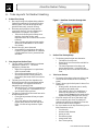
A. Tube Layouts for Radiant Heating
1. Radiant Floor Heatng
a. Hot water flowing in the radiant tubing under the
finished flooring heats the flooring and the heat
emission plates. The heat emission plates help
spread the heat evenly across the flooring.
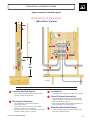
b. Heat must pass through the flooring and the
coverings on the floor (low pile carpeting and
thermal pads, for example). See Figure 1.
• The more the flooring and coverings act as
insulators, the higher the tube water
temperature has to be to cause the floor surface
to heat up.
• Heavy carpeting and pads resist heat transfer
and are not recommended for use in radiant
floor heating.
c. Heat will also try to move downward.
• In suspended floor applications, heat will try
to pass to the space underneath. So insulation
is needed under the floor to prevent this heat
movement.
2. Heat Output from Radiant Floors
a. The floor surface is usually heated to a maximum
temperature of about 85
o
F - the surface
temperature of human skin.
• Higher floor temperatures in occupied areas
could be uncomfortable.
• Floor surface temperatures up to 92
o
F are
often used around the outside perimeter of
rooms and in other areas where foot contact is
limited.
b. The heat given off by the floor depends on the
difference between the room temperature and the
floor temperature - the larger the difference in
temperature, the greater the heat.
• With the floor at 85
o
F and room temperature at
70
o
F, each square foot of the heated floor will
give off about 30 Btu’s per hour.
c. The spacing of tubes affects how much heat can be
moved through the floor.
• Closer spacing increases the heat per square
foot of floor.
• This is why tubes are often spaced closer
together along outside walls with high heat
losses - like next to large windows or patio
doors.
InsulationInsulation
TubeTube
Heat Emission PlateHeat Emission Plate
SleepersSleepers SleepersSleepers
SubfloorSubfloor
PadPad
CarpetCarpet
SubfloorSubfloor
JoistJoist
Figure 1 - Heat flow from tube through slab
3. Radiant Floor Heating Design
a. The heating system designer must determine:
• The heat loss for each room.
• Square feet of room floor surface available for
floor heating.
• The water temperature in the tubing and
spacing between tubes - to match the heat
given off by the floor to the heat lost from the
room.
4. Tube Layout Patterns
a. The routing of the tubing in the room affects room
comfort and effectiveness of the floor heating
system.
b. Figure 2 shows typical tube layouts for above floor
installations.
• Where possible, the hottest water is usually
routed along the outside walls.
• Tube routing in above floor installations is
limited by the practicality of variations in
sleeper layouts. Sleepers are the boards used to
separate the tubing and support the flooring.
c. Where the outside wall loss is particularly high,
such as caused by patio doors, the tubing will
sometimes be spaced closer together for a few feet
out from the wall as shown in Figure 2.
b. Pay close attention to the key information given in
these illustrations, such as:
• flow direction
• minimum bend diameters
• spacing to walls
• heat emission plates
• passage under walls
• use of closer spacing

Above Floor Installation Guide
Part Number 650-000-221/0298
5
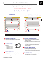
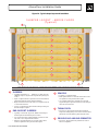
Figure 2 - Typical tube routing for an above floor installation
ABOVE FLOOR INSTALLATION
(One-Way Serpentine Patterns - Typical)
Constant Spacing
Outside Wall Concentrated Spacing
(Wall with large window area or cool wall)
These drawings are conceptual only. Consult Weil-McLain Radiant Guides or Software for actual project layout.
NOTE FLOW DIRECTION
!
The warmest water is directed next to the outside wall.
DISTANCE TO WALL
!
!
Keep the tubing 4 to 6 inches from the walls.
This will reduce the chance of damage due to drilling,
sawing or nailing.
USE HEAT EMISSION PLATES
!
!
!
Snap the tubing into AlumiPex Heat Emission Plates
placed on the sleepers.
These plates spread the heat evenly to the floor and ensure
that the tubing is maintained in tight contact with the
flooring above.
Staple the heat emission plates to the sleepers on one side
only to allow the plates to conform as the flooring or
subfloor is installed.
PASSAGE UNDER WALLS
!
!
Avoid running tube under walls if possible.
Where tubing must run under a wall, mark the framing
above for 6 inches on either side of this location so no
fasteners will be driven into the framing near the tubing.
CLOSER SPACING
!
Tubing is often spaced closer near outside walls with cool
surface temperatures or large window areas.
BEND DIAMETER
Maintain a MINIMUM bend
diameter of:
!
!
!
1/2“ Tube - 6 inches
5/8“ Tube - 7 inches
3/4“ Tube - 8 inches
Bend
Diameter
Interior Partition
Supply
Return
Interior Partition
Interior Partition
Outside Wall
Interior Partition
Interior Partition
Interior Partition
Supply
Return
Outside Wall

AlumiPex Radiant Tubing
Part Number 650-000-221/0298
6
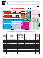
Normal Close
Inches Inches Feet Feet Feet Feet
LR1 Low pile carpet w/ thermal pad 8.5 178 43 10 231
LR2 Low pile carpet w/ thermal pad 8.5 6.5 192 22 10 224
DK Laminated hardwood 12.5 6.5 227 28 10 265
UT Ceramic tile 6.5 45 4 10 59
BT Ceramic tile 6.5 79 12 10 101
BR1 Laminated hardwood 8.5 6.5 141 22 10 173
BR2 Laminated hardwood 8.5 6.5 163 22 10 195
BR3 Laminated hardwood 8.5 6.5 156 19 10 185
Coil
Number
Coil Length Tube Size
Total
Length
1 1000 feet 1/2" 974
2 300 feet 1/2" 286
3 300 feet 1/2" 173
Use for Circuits Listed
Tubing
Circuit
Finished
Flooring
Total
Tube
Length
Tube Spacing
(Center to Center)
Circuit
Length
Leader
Length
Length
Allowance
LR1, LR2, DK, UT & BR2
BT & BR3
BR1
washer / dryer
Slab Control Joint
This drawing is conceptual only. Consult Weil-McLain Radiant Guides or Software for actual project layout.
DINING
BEDROOM
BEDROOM
BEDROOM
KITCHEN
U
T
I
L
I
T
Y
B
A
T
H
MANIFOLD
LIVING ROOM
DK
LR1
LR2
BR2
BR3
BT
UT
BR1
Figure 6 - Typical tube layout drawing

Above Floor Installation Guide
Part Number 650-000-221/0298
7
B. Obtain Tube Layout Drawing
1. Do not start a radiant heating installation without a
detailed tube layout drawing.
• It provides critical information on:
• tube routing
• tube lengths
• areas to be avoided
• materials needed
2. Figure 3 includes the information and drawing detail
for a typical tube layout drawing.
3. A complete, accurate drawing of the tube layout is the
most important key to a successful job.
Floor Plan/Layout Should . . . . . . . . . .
!
!
!
!
!
!
Be drawn to scale using a CAD program so tube
lengths can be calculated by the program.
Show complete floor plan, including all
appliances, cabinets, fireplaces and any other
details which could affect the routing of the
tubing.
Show complete layout of all circuits.
Provide length of each circuit, including leader
length. are the tubing runs connecting
from the room circuits to the manifold(s).
Show tube spacing and flow directions.
State finished flooring assumed for each space.
Leaders
The heating system designer may add an
allowance to the total length to account for
variations in actual installation. This might range
from 3 to 10% depending on the type of
installation. In the example shown at left, the
designer used a length allowance of 10 feet.
Note Tube Routing
!
!
!
!
!
Run leaders (connecting tubing from manifolds to
circuits) through hallways.
Run leaders and tubing under doorways.
Avoid running under walls to reduce chances of
damage from fasteners.
Mark the framing above where tubing runs under
walls so all trades will be aware.
If tubing must penetrate a firewall, follow local
codes regarding sleeving and fire stopping
requirements.
DO NOT Run Tubing:
!
!
!
!
!
Under cabinets, refrigerators, ranges, freezers.
These items "block" the heat and the tubing would
be wasted.
Within 8 inches of toilet flanges. The wax ring
seal may soften and fail from the heat.
Under fireplaces, ovens, appliances or other heat
sources.
Closer than 4" from walls.
Closer than 6" from appliance vents or flues.

AlumiPex Radiant Tubing
Part Number 650-000-221/0298
8
1. We suggest you meet with the general contractor
and follow this checklist:
q Review the AlumiPex Trade Guides with the
general contractor and ask him to provide the
information and copies to each of the trades
involved.
q Verify that the flooring system is rated by the
flooring manufacturer for use with heated floors.
q Verify architectural details affected by the
flooring system. Verify that the building designer
has allowed for the following:
The rough openings for doors and windows
allow for the height of the flooring system.
Stair risers include allowance for the height
of the flooring system.
q Ensure that the tubing will be stored inside until
time for use.
AlumiPex is specially designed to protect the
tubing from damaging ultraviolet rays.
However, avoid exposing the tubing to direct
sunlight for extremely long periods.
Do not install AlumiPex tubing in
applications which will continuously expose
the tubing to direct sunlight.
q Discuss the tube layout drawing with the general
contractor and verify:
floor plan design has not been changed.
finished floorings (and coverings) shown by
heating system designer are correct per final
design.
C. Meet with General Contractor
q If the tubing passes under any interior walls, you
should mark these locations on the framing
above.
Ask the general contractor to notify other
trades to watch for these markings to ensure
tubing will not be damaged by fasteners.
q If the tubing passes through stud walls, the
framing carpenters should apply nail stops on
both sides of the stud at these locations.
Ask the general contractor to notify other
trades to watch for these locations to ensure
tubing will not be damaged by fasteners.
q A copy of the tube layout drawing should be
given to the general contractor to ensure a
trouble-free installation.
You will probably want to provide a final
copy after the installation is complete.
The final copy should show special
notations, any changes from the original
plan, and locations of any repairs.

Above Floor Installation Guide
Part Number 650-000-221/0298
9
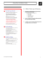
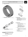
D. Obtain Materials
3. AlumiPex Manifolds
• Available in three sizes (2, 3 and 4 takeoff) in
nickel-plated brass (shown above), with or without
integral balancing valves .
• Copper manifolds (not shown) are also available.
• Refer to AlumiPex Manifold Instructions for part
numbers and procedures.
4. Additional Materials
a. AlumiPex Heat Emission Plates
• These are sized and designed specifically for
use with AlumiPex ½” tubing.
• See Figure 11, Page 16.
• Do not apply tubing in above floor
installations without heat emission plates.
Heat will be uneven and could cause
shrinkage or damage to flooring.
b. Staples
• Use staples sized so as not to penetrate deeper
than the subfloor. Usually, 5/8” staples will
work well.
c. Poly-wrapped insulation (if not already installed in
joist bays below)
e. Manifold Enclosure(s) (Optional)
• 30” x 27” or 30” x 37”.
2. AlumiPex Tube Fittings
• Refer to AlumiPex Fitting Instructions for part
numbers and procedures.
1. AlumiPex Tubing
• In rolls and sizes specified on tube layout drawing.
Use only AlumiPex Fittings with AlumiPex
Tubing. Use of any other method can result in
severe personal injury, death or substantial
property damage.
Refer to AlumiPex Fitting Instructions for
selection and application of fittings.

AlumiPex Radiant Tubing
Part Number 650-000-221/0298
10
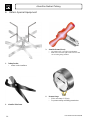
E. Obtain Special Equipment
1. Tubing Uncoiler
Assists in tube installation.
2. AlumiPex Tube Cutter
4. Pressure Gauge
With a scale range of 150 psig.
For pressure testing and tubing pressurization.
3. AlumiPex Reamer/Sizer(s)
The reamer/sizer is specific to tube diameter.
Make sure to have the right reamer/sizer for each
size of tubing being installed.

Above Floor Installation Guide
Part Number 650-000-221/0298
11
G. Mark Floor Plan and Tube Layout on Subfloor
1. Use the Tube Layout Plan to mark the following on
the subfloor. Use several colors if possible to define
different elements and circuits.
See Figure 7 for typical layout markings for the
system shown in Figure 6, page 6.
Mark wall lines and door openings (if interior
framing is not already installed).
Mark outlines of kitchen and bath cabinets,
appliances, etc.
F. Pre-Installation Check List
q Subfloor must be installed.
q Interior framing should be completed, but drywall
and finish carpentry not in place if possible.
q Review AlumiPex Trade Guides with general
contractor to ensure other trades will be informed.
q Make provision for pressure testing:
• Water if no freeze concern.
• Otherwise, air compressor and hoses for air test and
pressurization.
q Read this installation guide, the AlumiPex Fitting
Instructions and AlumiPex Manifold Instructions
thoroughly.
Return Bends (typical)
Counters and Avoidance
Areas (Typical)
Counters and Avoidance
Areas (Typical)
Return Bends (typical)
Manifold
Penetration Holes
(Typical)
Penetration Hole (Typical)
Leader Routing
(typical)
Leader Routing
(typical)
This drawing is conceptual only. Consult heating system designer for actual job details.
Figure 7 - Possible layout markings on subfloor for portion of system shown in Figure 6
Mark areas to be avoided (fireplaces, toilet
flanges, etc.).
Then mark key portions of the tube layout,
showing tube bend locations and flow direction.
• Mark locations of penetration holes in rooms
and hallways, if any.

AlumiPex Radiant Tubing
Part Number 650-000-221/0298
12
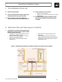
H. Mount Manifold(s)
1. Accurately measure the location of the manifold
mounting wall (if not already installed).
Placement of the manifold and the tube
penetrations is critical.
Take extra care in laying out these locations so all
items will be in proper position for the interior
framing of the building.
2. Attach the manifold to a plywood panel.
Size the panel to fit between the finished studs if
the panel is to be recess mounted.
Longer manifolds will require spanning more than
one stud spacing.
For a complete metal cabinet enclosure, use
AlumiPex Wall Cabinets.
See Figure 8 for a typical manifold mounting
arrangement.
3. Prepare holes for tube routing.
Drill 1½” holes through the studs to route tubing
to upper floors. See Figure 9 for drilling
penetration holes in the rooms above.
Drill 1½” holes through the sole plate in the
manifold stud cavity for penetrations to route
tubing to same floor or lower floor heating circuits.
Route same floor tubing through the joist bays
below and then up through holes in each room
unless the tubing will be routed through a hallway
as in Figure 6. Here, the tubing would be routed to
the joist bay below, then up to the proper locations
in the hallway to route to the rooms. This method
provides a neat installation while allowing ample
room for tube bending.
When drilling the holes for tube penetration into
the rooms or hallway, drill the holes at a 45 degree
angle to provide the proper minimum bend
diameter for the tubing. See Figure 9, Page 14.

Above Floor Installation Guide
Part Number 650-000-221/0298
13
Figure 8 - Mounting of manifold(s), typical
MANIFOLD MOUNTING
(Above Floor System)
The details shown are representative only. Other mounting configurations are possible.
AlumiPex Manifold, Typical
!
Refer to AlumiPex Manifold Instructions for details of
mounting, assembly and application.
Protect Tubing at Penetrations
!
!
Where tubing passes through stud walls, make sure nail
stoppers are installed on both sides of the stud to protect
tubing from damage by fasteners.
Make sure the drywall installers and finish carpenters are
aware of the tubing in the walls and floors.
AlumiPex Manifold Fittings
!
Refer to AlumiPex Fitting Instructions for selection and
application of AlumiPex fittings.
Mounting Configuration
!
!
!
The installed depth of the manifold assembly is
approximately 4 inches.
If mounted on 3/4“ plywood as shown, the complete
assembly would fit in a 5” deep enclosure.
This can be done by using 2 x 6 studs in the vicinity of the
manifold or building out from 2 x 4 studs.
Junction Box
!
Junction box for manifold valve actuator wiring, if needed.
Dry Wall
Joist Bays
Subfloor
Lower Plate
Dry Wall
Studs
24“
Min
SUPPLYSUPPLY
RETURNRETURN
Cover
4“
RETURN
SUPPLY
Joists

AlumiPex Radiant Tubing
Part Number 650-000-221/0298
14
I. Install the Tubing
1. Install the sleepers.
Beginning from one side of each room, use your
floor markings and the tube layout drawing to
place the sleepers.
Glue and nail each sleeper in place as shown in
Figure 10.
Bend routing sleepers can be made using a router
and fixture as shown or using a saber saw to cut
semicircles.
2. Drill tube penetration holes.
If the tubing will penetrate the floor in the room,
drill a 1½” hole at a 45 degree angle for each
penetration as shown in Figure 9.
Make sure the tube can be routed through the hole
from below and provide a minimum 6 inch bend
diameter (3 inch bend radius) for 1/2” tubing.
3. Install heat emission plates.
Install AlumiPex Heat Emission Plates in the
sleeper spaces, centered in the 1” gap.
Secure heat emission plates on one side only to the
sleeper below using 5/8” staples.
Leave the other side of the heat emission plates
free to move so the plates can conform to the floor
as the upper subfloor or finished flooring is
installed.
See Figure 11 for typical details.
4. Place tube roll on uncoiler.
5. Route free end of tubing to manifold.
Feed the free end of the tubing through any
penetration holes to the manifold.
6. Install manifold fitting on free end of tube.
a. AlumiPex Nickel-Plated Brass Manifolds:
Use only AlumiPex Euro conical fittings.
Refer to AlumiPex Manifold Instructions for
details and part numbers.
b. AlumiPex Copper Manifolds:
Use only AlumiPex tubing to NPT connectors.
7. Attach tube fitting to manifold SUPPLY connection
(bottom manifold).
8. Feed the tubing to the room as shown on the heating
system designer’s tube layout drawing, feeding the
outer (SUPPLY) tubing first.
9. Complete the layout for the circuit and route the
tubing back to the return manifold as shown on the
tube layout drawing.
10. Carefully cut the tubing to the correct height at the
return manifold. Apply an AlumiPex fitting for
attachment to the manifold.
11. Then attach the fitting to the RETURN (top) manifold.
12. Continue the process for each circuit.
13. See Figure 11, page 16, for an above floor
construction example.
Always wear safety glasses for eye protection
when handling AlumiPex tubing. The tubing
can spring back when pulled. Failure to follow
this guideline could result in serious personal
injury.
Figure 9 - Tubing penetration hole, typical
Joist, Typical
1/2" Tubing, Typical
(With 6" bend diameter)
Drill penetration holes
1½" diameter on 45
degree angle.
SubfloorSubfloor
SleeperSleeper
45
degrees

Above Floor Installation Guide
Part Number 650-000-221/0298
15
Figure 10 - Typical sleeper layout and installation
5 5
5
SLEEPER LAYOUT - ABOVE FLOOR
(Typical)
1
SLEEPERS
!
!
!
!
Typically sleepers are 1 x __ lumber or .
Space 1" apart as shown to provide room for heat emission
plate tubing channel and for thermal expansion.
Begin at one side of the room. Place a 1 x 4 spacer (item 3)
" from wall as shown.
Leave a 1" gap between spacer and first sleeper. Then glue
and nail sleepers in place.
(Width of sleeper is equal to the required tube spacing less
1 inch.)
¾" CDX plywood
¼
2
END SUPPORT SLEEPERS
!
!
!
Typically cut from 3/4" plywood.
Use a router and circle cutting template or fixture to route
3/4" wide x 5/8" deep channels as shown..
Place the end supports about " from the wall to allow
room for expansion. Then glue and nail in place.
(Width of end sleepers
should equal tube bend radius plus 4 inches.)
¼
3
SPACERS
!
!
!
Typically 1 x 4 furring strips.
Place spacers about from the wall to allow room
for expansion. Then glue and nail in place.
Use a spacer between the wall and one of the end
support sleepers to provide a channel for the tubing to
leave the room as shown.
¼"
4
TUBING PATH
!
Provide a 1" gap between spacer and end support
sleeper for routing tubing out of room. This will allow
placement of a heat emission plate along this route.
5
PROVIDE GAP AROUND PERIMETER
!
Provide " gap around entire perimeter of room to
allow for expansion.
¼
These drawings are conceptual only. Consult Weil-McLain Radiant Guides or Software for actual project layout.
1
1
1
1
1
1
1
2
2
3
4
4
4
4
4
4
4
4
4
3

AlumiPex Radiant Tubing
Part Number 650-000-221/0298
16
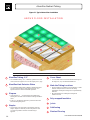
Figure 11 - Typical above floor installation
ABOVE FLOOR INSTALLATION
This drawing is conceptual only. Consult Weil-McLain Radiant Guides or Software for actual project layout.
A
Finished Flooring
J
J
Subflooring
I
I
Joists
H
H
Poly-wrapped Insulation
G
Mark the Tubing Locations
!
!
Always mark the top subfloor with a chalk line or other
mark to clearly show the location of the tubing
underneath, ensuring the tubing won't be penetrated by
fasteners.
Pay extra attention to marking the tubing bend
locations as well.
F
F
Cover Sheet
!
A cover sheet must be used if the finished flooring will
be carpet, tile, vinyl or laminated hardwood.
E
E
D
Staples
!
Secure each 2-foot long plate to the sleepers with 5/8"
staples. Staple one side only to allow the plates to level
out as the top subfloor or finish wood flooring is
applied..
D
Sleepers
!
!
Glue and nail 1 x __ wood sleepers to the subflooring,
starting from one side of the room and working toward the
other.
Leave a 1" gap between sleepers to provide room for the
heat emission plate groove.
C
C
AlumiPex Heat Emission Plates
!
Use AlumiPex Heat Emission Plates to distribute the heat
evenly to the floor above. Space plates from 1/4” to 1”
apart end to end to allow for thermal expansion.
B
B
AlumiPex Tubing, 1/2”
A
!
Use AlumiPex tubing, 1/2”, commonly spaced on 6½-inch
centers as shown (equal to 5½" for the sleeper plus 1" gap).
G

Above Floor Installation Guide
Part Number 650-000-221/0298
17
J. Pressure Test the Finished Tubing Installation
1. After all tubing has been routed and connected to the
manifold, pressure test all tubing circuits before
finished flooring is installed. Refer to AlumiPex
Manifold Instructions.
2. Isolate the AlumiPex manifolds and tubing from any
other piping.
3. Attach a pressure gauge with a 150 psig scale range
to the manifold using a high pressure hose.
• Locate the gauge so it can be read during all
phases of construction.
4. Fill the system for pressure test with water only if
there is no freeze potential.
• You will need to keep the system pressurized as
discussed in the next section.
• So the fluid used for testing would have to remain
in place.
• You must be sure, if using water, that no freeze
potential would exist from time of installing pipe
until time for you to complete the system piping
and fill the system for start-up.
5. If there is freeze potential, fill the system with air and
perform the pressure test using air.
• If using air, remove all air vents from the manifolds
and plug the openings.
6. Pressurize the system to between 70 and 100 psig for
30 minutes.
a. Observe the pressure on the gauge.
b. The pressure should not drop unless testing with
air on a cold day.
• On cold days, air pressure testing will show
a drop as the air in the tubing cools off. But
the pressure should reach a steady level and
drop no further.
• If the pressure does drop, check the
connections at the manifolds first.
c. Examine the system for leaks. Repair any leaks
found and repeat the test.
d. Check threaded joints with leak detection fluid
(soap mixture if using air).
Failure to check for and repair leaks can result
in damage to system components and the
premises, causing severe personal injury, death
or substantial property damage.
When pressure testing with air, or when air is
left anywhere in the system being pressurized,
there is a risk of explosive discharge of
compressed air or water if a leak or break
occurs.
Do not leave these pressure tests unattended
while others are present.
Remove all non-essential persons from the
area during pressure testing.
Failure to follow these guidelines could lead
to severe personal injury, death or substantial
property damage.

AlumiPex Radiant Tubing
Part Number 650-000-221/0298
18
K. Pressurize Tubing for Observation
1. After the system has been proven leak free, pressurize
all tubing circuits to 30 psig.
Maintain this pressure on the tubing for the
remainder of the building construction.
Pressurizing the tubing allows use of the pressure
gauge to verify the integrity of the tubing and
connections.
Periodically observe the pressure gauge to make
sure no major drop in pressure occurs. A pressure
drop would indicate a puncture or leak.
1. Before leaving the jobsite, we recommend you meet
with the general contractor to review the AlumiPex
Trade Guides.
q Make special note of the pressure gauge. It can be
used by all trades to check the integrity of the
tubing throughout the construction of the
building.
q Review traffic recommendations.
q Ask for early notification of the schedule for
installing finished flooring so you can inspect the
installation a day before this starts.
M. Before Leaving the Jobsite . . .
q If possible, get an agreement that the flooring
won’t be installed until you have inspected the
installation and given your release.
2. Make a record of your installation
We suggest you take photographs of the tubing
and manifolds.
Use the photographs and notes on the tube layout
drawing to document installation details.
L. Connect System Piping & Heating System Components
1. Install piping and heating system components if
framing is in place.
3. Don’t solder within 18 inches of tubing.
3. Cover tubing to protect it from solder drip.
4. Never apply an open flame to AlumiPex tubing.
5. Pressure test sytem piping to verify there are no
leaks.

Above Floor Installation Guide
Part Number 650-000-221/0298
19
O. Inspection, Repair and Troubleshooting
1. Inspect the tubing connections and piping as the job
is completed.
2. Perform a final pressure test on the system after all
flooring is in place and building is ready for
occupancy to verify all joints are tight and no
damage has occurred to the tubing during
construction.
3. Repair of kinked or crushed tubing:
Use a copper pipe truer to restore the tubing
roundness.
If the damage is so severe that this cannot be done,
cut out the damaged section of tubing.
• Cut a new length of tubing long enough to
span the gap.
• At each end of the splice section, install an
AlumiPex coupling.
• Slip a length of heat shrink tubing over each
end before tightening the couplings.
• Tighten couplings. Then seal them with the
heat shrink tubing.
• Route a groove in the subflooring deep
enough to accommodate the finished repair
section.
• Mark the location of any such repairs on the
tube layout drawing
N. Inspect Tubing Before Finished Flooring Installation
1. Arrange to inspect the installation a day before the
scheduled finished flooring installation starts.
q Check the pressure gauge to verify the system is
still pressurized at or near 30 psig.
q Visually inspect all tubing to verify there is no
damage.
q Repair any damage you find.
q Advise the general contractor of your findings and
release for finished flooring installation.

-
 1
1
-
 2
2
-
 3
3
-
 4
4
-
 5
5
-
 6
6
-
 7
7
-
 8
8
-
 9
9
-
 10
10
-
 11
11
-
 12
12
-
 13
13
-
 14
14
-
 15
15
-
 16
16
-
 17
17
-
 18
18
-
 19
19
-
 20
20


Weil-McLain AlumniPEX User manual
- Type
- User manual
- This manual is also suitable for
Ask a question and I''ll find the answer in the document
Finding information in a document is now easier with AI
Related papers
-
Weil-McLain 14 User manual
-
Weil-McLain CGA3PIDN Owner's manual
-
Weil-McLain GOLD GV User manual
-
-
-
Weil-McLain ULTRA ULTRA-80 User manual
-
Weil-McLain GV90+ Gas Boiler User manual
-
-
-
Other documents
-
VENTS-US D250X300 Installation guide
-
EASTMAN 98593 Installation guide
-
EZ-FLO 98587 Installation guide
-
WarmlyYours TRT120-1.5x09 Nailed Down Hardwood Installation
-
-
 Hebel Design Matthew’s Signet Ring’ Operating instructions
-
Design House 531319 Installation guide
-
Lopi Radiant Plus Large™ Gas Fireplace Insert User manual
-
Rehau RAUBOARD Product Instructions
-
QuietWarmth QWJOIST17X10120 Installation guide
