Page is loading ...

© Copyright 2005, DB Industries, Inc.
User Instruction Manual For Davit Rescue System
This manual should be used as part of an employee training
program as required by OSHA.
Instructions for the following
series products:
Rescue Davit System
Model numbers 8004000 and
8302500


3
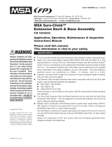
Figure 1 - Davit Arm & Base Parts Identication
PULLEY
REFLECTIVE LABEL
UPPER ARM
WINCH
DETENT PIN
LOWER ARM
BASE STORAGE STRAP
BASE
DAVIT ARM
STORAGE
STRAP
CRANK ARM WITH
FOLDING HANDLE
LEG
FOOT
BASE SOCKET
WINCH
LINE
LIFTING
HOOK
DAVIT
ARM
WITH
WINCH
ID AND WARNING LABEL
CARRYING HANDLE
ID AND
WARNING
LABEL

4
WARNING: This product is part of a rescue or evacuation system. The
user must read and follow the manufacturer’s instructions for each
component or part of the complete system. These instructions must
be provided to the user of this equipment. The user must read and
understand these instructions or have them explained before using this
equipment. Manufacturer’s instructions must be followed for proper use
and maintenance of this product. Alterations or misuse of this product or
failure to follow instructions may result in serious injury or death.
IMPORTANT: If you have any questions on the use, care, application, or
suitability for use of this safety equipment, contact DBI/SALA immediately.
IMPORTANT: Before using this equipment, record the product
identication information found on the I.D. label of your Rescue Davit
System on the inspection and maintenance log in section 9.0 of this
manual.
DESCRIPTIONS:
Davit Arm: Portable davit arm with rescue winch and base. Aluminum
and zinc-plated steel construction, see Figure 1.
1.0 APPLICATIONS:
1.1 PURPOSE: DBI/SALA’s Rescue Davit System is designed to be used
as part of a rescue or evacuation system. The davit arm and base acts
as a support structure or anchorage for this purpose.
1.2 LIMITATIONS: The following limitations must be recognized and
considered before using this product. Failure to observe product
limitations could result in serious injury or death.
A. INSTALLATION: The davit arm and base must be properly
installed in accordance with the requirements found in section 3.0
of this manual.
B. CAPACITY: The maximum working load for this product is 350
lbs. (160 kg) for personnel or 175 lbs. (80 kg) for material.
C. PERSONAL FALL ARREST SYSTEMS: This Rescue Davit System
is not designed to be used as an anchorage for fall arrest purposes.
D. PHYSICAL AND ENVIRONMENTAL HAZARDS: Use of this
equipment in areas containing physical or environmental hazards
may require that additional precautions be taken to reduce the
possibility of damage to this equipment or injury to the user(s).

5
Hazards may include but are not limited to high heat such as
welding or metal cutting, strong or caustic chemicals such as
acids, corrosive environments such as exposure to sea water, high
voltage power lines, explosive or toxic gases, moving machinery
or sharp edges. Contact DBI/SALA if you have any questions
about the application of this equipment in areas where physical or
environmental hazards are present.
E. TRAINING: This equipment is intended to be installed and
used by persons who have been properly trained in its correct
application and use.
1.3 Refer to national consensus standards including ANSI Z117.1-1989,
applicable local, state and federal (OSHA) requirements including
26 CFR 1910.146, for more information on the application of this and
associated equipment.
2.0 SYSTEM REQUIREMENTS
2.1 COMPATIBILITY OF COMPONENTS: DBI/SALA equipment
is designed for use with DBI/SALA approved components and
subsystems only. Substitutions or replacements made with non-
approved components or subsystems may jeopardize compatibility
of equipment and may effect the safety and reliability of the complete
system.
2.2 COMPATIBILITY OF CONNECTORS: Connectors are considered
to be compatible with connecting elements when they have been
designed to work together in such a way that their sizes and shapes
do not cause their gate mechanisms to inadvertently open regardless
of how they become oriented. Contact DBI/SALA if you have any
questions about compatibility.
Connectors (hooks, carabiners, and D-rings) must be capable
of supporting at least 5,000 lbs. (22.2kN). Connectors must be
compatible with the anchorage or other system components. Do not
use equipment that is not compatible. Non-compatible connectors
may unintentionally disengage. See Figure 2. Connectors must be
compatible in size, shape, and strength. Self locking snap hooks and
carabiners are required by ANSI Z359.1 and OSHA.
2.3 MAKING CONNECTIONS: Only use self-locking snap hooks and
carabiners with this equipment. Only use connectors that are suitable
to each application. Ensure all connections are compatible in size,
shape and strength. Do not use equipment that is not compatible.
Ensure all connectors are fully closed and locked.

6
DBI/SALA connectors (snap hooks and carabiners) are designed to
be used only as specied in each product’s user’s instructions. See
Figure 3 for inappropriate connections. DBI/SALA snap hooks and
carabiners should not be connected:
A. To a D-ring to which another connector is attached.
B. In a manner that would result in a load on the gate.
NOTE: Large throat opening snap hooks should not be connected to
standard size D-rings or similar objects which will result in a load on the
gate if the hook or D-ring twists or rotates. Large throat snap hooks are
designed for use on xed structural elements such as rebar or cross
members that are not shaped in a way that can capture the gate of the
hook.
C. In a false engagement, where features that protrude from the
snap hook or carabiner catch on the anchor and without visual
conrmation seems to be fully engaged to the anchor point.
D. To each other.
E. Directly to web lanyard or rope lanyard or tie-back (unless the
manufacturer’s instructions for both the lanyard and connector
specically allow such a connection).
If the connecting element that a snap hook (shown) or carabiner attaches to is
undersized or irregular in shape, a situation could occur where the connecting
element applies a force to the gate of the snap hook or carabiner. This force
may cause the gate (of either a self-locking or a non-locking snap hook) to open,
allowing the snap hook or carabiner to disengage from the connecting point.
1. Force is applied to
the snap hook.
2. The gate presses against
the connecting ring.
3. The gate opens allowing
the snap hook to slip off.
Small ring or other
non-compatibly
shaped element
Figure 2 - Unintentional Disengagement (Roll-out)

7
F. To any object which is shaped or dimensioned such that the snap
hook or carabiner will not close and lock, or that roll-out could
occur.
2.3 STRUCTURAL STRENGTH: The structure (mounting surface) to
which the Rescue Davit System is installed must meet minimum
strength requirements:
The structure (mounting surfaces) selected for rescue applications
must be capable of sustaining a static load of at least 1,400 lbs.
applied in the direction(s) permitted by the rescue system when in use.
Each Rescue Davit System installation must be independently capable
of sustaining this load.
3.0 OPERATION AND USE:
WARNING: Do not alter or intentionally misuse this equipment, your
safety may depend on it. Consult DBI/SALA when using this equipment in
combination with components or subsystems other than those described
in this manual. Some subsystem and component combinations may
interfere with the proper operation of this equipment. Use caution when
using this equipment around moving machinery or electrical hazards.
Use caution when using this equipment around sharp edges or chemical
hazards.
3.1 BEFORE EACH USE: Before each use of this equipment carefully
inspect it to assure that it is in serviceable condition. Check for worn
or damaged parts. Ensure all parts (nuts, bolts, etc) are present and
Figure 3 - Inappropriate Connections

8
secure. Check davit arms and base legs to ensure they are straight,
free of cracks, dents, etc. Check the overall system for signs of severe
corrosion. Refer to section 5.0 for further inspection details. Do not
use if inspection reveals an unsafe condition.
3.2 PLANNING: Plan your rescue or evacuation system before starting
your work. Take into consideration factors that affect your safety at
any time during use. Some important points to consider when planning
your system are as follows:
A. HAZARD EVALUATION: An evaluation of job site hazards is
necessary prior to starting work. Consult applicable OSHA and
industry standards for guidelines and regulatory requirements.
B. WORK SITE GEOMETRY: The installation and use of the Rescue
Davit System must be consistent with the geometric requirements
given in section 3.4 or 3.5. When suspending winch line from the davit
arm, check for obstructions or sharp edges in the work path. Avoid
working where the user may swing and hit an object or where lines
may cross or tangle with that of another worker in the area.
C. RESCUE: In the event of an accident with injuries or other medical
emergency, it is critical that a means of dealing with such a situation
has been planned in advance. Response time often plays an important
role in the survival of an injured worker. Users of this equipment must
be trained in emergency procedures as appropriate.
3.4 INSTALLATION OF FIXED BASE
A. GEOMETRIC REQUIREMENTS: The base must be mounted on a
surface that is sufciently level such that tipping of the base cannot
occur during use. See Figure 4. Position the base such that the
pulley will be directly over the intended work area when installed.
Avoid positioning the base where, when in use, the winch line may
abrade against sharp edges.
IMPORTANT: The base must be positioned such that the arm will be as
directly as possible over the intended work area when installed. It also must be
positioned in such a way to ensure a safe working area for the operator.
3.5 INSTALLATION OF DAVIT ARM TO THE BASE: Place the lower
arm of the davit arm into the base socket and lower the arm down into
the base, see Figure 5. Next, lift the upper arm into position and pin
in place, then rotate the arm into position over work area. Ensure that
once installed, the winch line will remain within the feet of the base to
prevent tipping. See Figure 4.

9
3.6 OPERATION OF WINCH: To operate the winch, fold the handle
out on the crank arm to ready the winch for use. See Figure 6. To
lower the load, or extend line from the winch, rotate the crank arm in
a counterclockwise
direction. Note, if
there is no load on
the winch line, it may
be necessary to feed
line off the winch by
pulling on the hook end
of the winch line. To
raise the load, rotate
the crank arm in the
Figure 4 - Installation
Figure 5 - Installation
Detent Pin
Figure 6 - Folding Handle
To fold, pull handle out away from crank arm and
rotate outer end of handle toward crank arm.

10
clockwise direction. When winding the winch line onto the winch for
storage, ensure the line is not excessively loose and is wound evenly.
This winch includes
a rachet feature
that may be used
when raising a load
( the rachet must
be disengaged
for lowering). The
rachet is used to
hold the load if the
operator releases
control of the crank
arm. See Figure 7
for operation of the
rachet.
3.7
STORAGE:
Figure 8 shows the davit arm
and base folded for storage,
An eye bolt is provided on the
davit arm for connection of the
lifting hook when the unit is to
be stored. Install the detent pin
into the arm when stored to
protect it against damage and
loss. Both the davit arm and
base include storage straps that
should be wrapped and connected to secure the units during storage.
3.8 MAINTENANCE:
Lubricate winch gears at least once each year. Apply a light lm of
open gear lubricant to the gear teeth on all gears. Use Sprayon 201 or
equivalent open gear lube. For dirty conditions, use CRC dry graphite
lube.
Lubricate winch bearings and shafts at least once each year. Apply 2
to 3 drops of SAE 30 non-detergent oil or “3 in 1” oil to bearings and
shafts at all friction points. Rotate the drum several times to allow the
oil to penetrate, and wipe off excess oil to avoid accumulation of dirt.
Lubricate the disk brake at least once each year. Place 1 or 2 drops
of SAE 30 non-detergent oil or “3 in 1” oil into the hole in the brake
housing and turn the brake several times to allow the oil to penetrate.
Figure 7 - Activate Rachet
Figure 8 - Storing Davit Arm & Base

11
4.0 TRAINING:
4.1 It is the responsibility of the user and the purchaser of this equipment
to assure that they are familiar with these instructions, trained in the
correct care and use of and are aware of the operating characteristics,
application limits and the consequences of improper use of this
equipment.
IMPORTANT: Training must be conducted without exposing the trainee to
a fall hazard. Training should be repeated on a periodic basis.
5.0 INSPECTION:
5.1 FREQUENCY:
• Before Each Use: Visually inspect per steps listed in sections 5.2.
• Periodic A formal inspection of the davit arm, base, and winch
should be conducted by a competent person on a periodic basis
as established by the user’s organization. DBI/SALA recommends
this inspection be conducted at least annually. See section 5.2 for
guidelines. Record results in Inspection And Maintenance Log in
section 9.0.
WARNING: If the davit arm or base fails to pass the inspection, do not
use, the equipment must be destroyed or sent to DBI/SALA for possible
repair.
5.2 INSPECTION POINTS FOR DAVIT ARM, BASE, AND WINCH:
• Inspect all bolts and nuts. Make certain they are securely attached
and tight. Check if any bolts, nuts or other fasteners are missing or
have been substituted or altered.
• Check all tubular sections, ensure they are straight and free of
cracks, dents, distortion or other damage.
• Ensure the davit arm opens properly and can be locked into place
with the detent pin. Ensure the legs open properly.
• Inspect the pulley to ensure it is clean and rotates freely.
• Inspect the base, ensuring it is not damaged and is free of cracks,
dents, bends, distortion or other damage.
• Inspect the feet, ensuring they are not damaged and are free of
cracks, dents, bends, distortion, or other damage.

12
• Inspect the unit for signs of corrosion which may weaken or
otherwise affect parts in their function.
• Ensure all labels are present and fully legible. See section 8.0.
• Inspect the winch for cracks, dents, bending, rust, wear, corrosion,
or other damage.
• Ensure the winch line is anchored securely to the drum.
• Ensure the winch and brake are properly lubricated.
• Ensure fasteners are installed to hold the crank handle in place.
• Test the winch performance by raising a test weight of 100 lbs.
Listen for unusual noises and look for signs of damage as the winch
is operated. Lower the load and stop it above the ground. If the load
continues to coast or creep, the friction disks may be worn and in
need of replacement.
• Ensure the winch line winds evenly and tightly onto the drum. If the
winch line is loose or uneven, rewind it.
• Ensure the crank handle rotates freely in both directions.
• Ensure the ratchet engages and disengages.
• Record results of inspection in Inspection & Maintenance Log found
in section 9.0 of this manual.
• Inspect other system components (ex. body support, etc.) per
associated manufacturer’s instructions.
5.3 If inspection or operation reveals a defective condition, remove
the Rescue Davit System from service immediately and contact an
authorized service center for repair.
NOTE: Only DBI/SALA or parties authorized in writing may make repairs
to this equipment.

13
6.0 MAINTENANCE - SERVICING - STORAGE:
6.1 Periodically clean the exterior of the Rescue Davit System using water
and a mild soap detergent solution. Clean labels as required.
6.2 Replacement parts as well as additional maintenance and servicing
procedures must be completed by a DBI/SALA factory authorized
service center.
6.3 Store this equipment in a cool, dry and clean environment out of direct
sunlight. Avoid areas where chemical vapors may exist. Inspect after
any period of extended storage.
7.0 SPECIFICATIONS:
The Rescue Davit System meets ANSI Z117.1-1989 and OSHA
requirements.
Rated (safe) Working Load:
350 lbs. (160 kg) rescue applications; 175 lbs. (80 kg) material
Davit Arm:
Reach: 24 inches
Height: 70 inches
Weight:
Davit Arm with Winch: 39 lbs.
Base: 38 lbs.
Material: Aluminum and Zinc-plated Steel
8.0 LABELING:
8.1 These labels should be securely attached to the Rescue Davit System.
See Figure 1 for locations.

14
Reective Label
ID and Warning Label

15
9.0 INSPECTION AND MAINTENANCE LOG
SERIAL NUMBER: ___________________________________________
MODEL NUMBER: ___________________________________________
DATE PURCHASED: _________________________________________
NOITCEPSNI
ETAD
NOITCEPSNI
DETONSMETI
EVITCERROC
NOITCA
ECNANETNIAM
DEMROFREP
:yBdevorppA
:yBdevorppA
:yBdevorppA
:yBdevorppA
:yBdevorppA
:yBdevorppA
:yBdevorppA
:yBdevorppA
:yBdevorppA
:yBdevorppA
:yBdevorpp
A

16
9.0 INSPECTION AND MAINTENANCE LOG
SERIAL NUMBER: ___________________________________________
MODEL NUMBER: ___________________________________________
DATE PURCHASED: _________________________________________
NOITCEPSNI
ETAD
NOITCEPSNI
DETONSMETI
EVITCERROC
NOITCA
ECNANETNIAM
DEMROFREP
:yBdevorppA
:yBdevorppA
:yBdevorppA
:yBdevorppA
:yBdevorppA
:yBdevorppA
:yBdevorppA
:yBdevorppA
:yBdevorppA
:yBdevorppA
:yBdevorpp
A

17
9.0 INSPECTION AND MAINTENANCE LOG
SERIAL NUMBER: ___________________________________________
MODEL NUMBER: ___________________________________________
DATE PURCHASED: _________________________________________
NOITCEPSNI
ETAD
NOITCEPSNI
DETONSMETI
EVITCERROC
NOITCA
ECNANETNIAM
DEMROFREP
:yBdevorppA
:yBdevorppA
:yBdevorppA
:yBdevorppA
:yBdevorppA
:yBdevorppA
:yBdevorppA
:yBdevorppA
:yBdevorppA
:yBdevorppA
:yBdevorpp
A

18
9.0 INSPECTION AND MAINTENANCE LOG
SERIAL NUMBER: ___________________________________________
MODEL NUMBER: ___________________________________________
DATE PURCHASED: _________________________________________
NOITCEPSNI
ETAD
NOITCEPSNI
DETONSMETI
EVITCERROC
NOITCA
ECNANETNIAM
DEMROFREP
:yBdevorppA
:yBdevorppA
:yBdevorppA
:yBdevorppA
:yBdevorppA
:yBdevorppA
:yBdevorppA
:yBdevorppA
:yBdevorppA
:yBdevorppA
:yBdevorpp
A


WARRANTY
Equipment offered by DBI/SALA are warranted against factory defects
in workmanship and materials for a period of two years from date of in-
stallation or use by the owner, provided that this period shall not exceed
two years from the date of shipment. Upon notice in writing, DBI/SALA
will promptly repair or replace all defective items. DBI/SALA reserves the
right to elect to have any defective item returned to its plant for inspec-
tion before making a repair or replacement. This warranty does not cover
equipment damages resulting from abuse, damage in transit, or other
damage beyond the control of DBI/SALA. This warranty applies only to
the original purchaser and is the only one applicable to our products, and
is in lieu of all other warranties, expressed or implied.
Form: 5902269
Rev: D
CSG USA
3833 Sala Way
Red Wing, MN 55066-5005
Toll Free: 800.328.6146
Phone: 651.388.8282
Fax: 651.388.5065
solutions@capitalsafety.com
CSG Canada Ltd.
260 Export Boulevard
Mississauga, Ontario L5S 1Y9
Toll Free: 800.387.7484
Phone: 905.795.9333
Fax: 905.795.8777
sales.ca@capitalsafety.com
www.capitalsafety.com
Certificate No. FM 39709
ISO
9001
/