Page is loading ...

OWNER’S MANUAL
High-Performance Powered Loudspeaker Series
SRM210 | V-Class
SRM212 | V-Class
SRM215 | V-Class

SRM | V-Class High-Performance Powered Loudspeaker Series
2
SRM | V-Class High-Performance Powered Loudspeaker Series
Important Safety Instructions
1. Read these instructions.
2. Keep these instructions.
3. Heed all warnings.
4. Follow all instructions.
5. Do not use this apparatus near water.
6. Clean only with a dry cloth.
7. Do not block any ventilation openings. Install in accordance
with the manufacturer’s instructions.
8. Minimum distance (5 cm) around the apparatus for sucient ventilation.
The ventilation should not be impeded by covering the ventilation openings
with items, such as newspapers, table-cloths, curtains, etc.
9. Do not install near any heat sources such as radiators, heat registers,
stoves, or other apparatus (including amplifiers) that produce heat.
10. No naked flame sources, such as lighted candles, should be placed
on the apparatus.
11. Do not defeat the safety purpose of the polarized or grounding-type plug.
A polarized plug has two blades with one wider than the other. A grounding-
type plug has two blades and a third grounding prong. The wide blade or
the third prong are provided for your safety. If the provided plug does not fit
into your outlet, consult an electrician for replacement of the obsolete outlet.
12. Protect the power cord from being walked on or pinched particularly at plugs,
convenience receptacles, and the point where they exit from the apparatus.
13. Only use attachments/accessories specified by the manufacturer.
14. Use only with a cart, stand, tripod, bracket, or table
specified by the manufacturer, or sold with the apparatus.
When a cart is used, use caution when moving the cart/
apparatus combination to avoid injury from tip-over.
15. Unplug this apparatus during lightning storms or when
unused for long periods of time.
16. Refer all servicing to qualified service personnel.
Servicing is required when the apparatus has been
damaged in any way, such as power-supply cord or plug is damaged, liquid has
been spilled or objects have fallen into the apparatus, the apparatus has been
exposed to rain or moisture, does not operate normally, or has been dropped.
17. This apparatus shall not be exposed to dripping or splashing, and no object filled
with liquids, such as vases or beer glasses, shall be placed on the apparatus.
18. Do not overload wall outlets and extension cords as this can result in a risk
of fire or electric shock.
PORTABLE CART
WARNING
CAUTION
The lightning flash with arrowhead symbol within an equilateral
triangle is intended to alert the user to the prescence of uninsulated
“dangerous voltage” within the product’s enclosure, that may be of
significant magnitude to constitute a risk of electric shock to persons.
RISK OF ELECTRIC SHOCK! DO NOT OPEN!
CAUTION: TO REDUCE THE RISK OF ELECTRIC SHOCK DO NOT
REMOVE COVER (OR BACK). NO USER-SERVICEABLE PARTS INSIDE.
REFER SERVICING TO QUALIFIED PERSONNEL.
The exclamation point within an equilateral triangle is intended
to alert the user of the prescence of important operating and
maintaining (servicing) instructions in the literature accompanying
the appliance.
WARNING — To reduce the risk of fire or electric shock, do not
expose this apparatus to rain or moisture.
CAUTION — To prevent electric shock hazard, do not connect
to mains power supply while grille is removed.
Laite on liitettävä suojakoskettimilla varustettuun pistorasiaan.
Apparatet stikprop skal tilsluttes en stikkontakt
med jord, som giver forbindelse til stikproppens jord.
Apparatet må tilkoples jordet stikkontakt.
Apparaten skall anslutas till jordat uttag.
19. This apparatus has been designed with Class-I construction and
must be connected to a mains socket outlet with a protective earthing
connection (the third grounding prong).
20. This apparatus has been equipped with a rocker-style AC mains power
switch. This switch is located on the rear panel and should remain readily
accessible to the user.
21. The MAINS plug or an appliance coupler is used as the disconnect device,
so the disconnect device shall remain readily operable.
22. The use of apparatus is in moderate climates.
23. This device should be installed and operated with minimum distance 20cm
between the radiator & your body.
The product can be sold in all EU countries.
Bluetooth transmitter Power: ≤9dBm
Bluetooth transmitter frequency range: 2.402 – 2.480 GHz
24. NOTE: This equipment has been tested and found to comply with the limits
for a Class A digital device, pursuant to part 5 of the FCC Rules. These
limits are designed to provide reasonable protection against harmful
interference when the equipment is operated in a commercial environment.
This equipment generates, uses, and can radiate radio frequency energy
and, if not installed and used in accordance with the instruction manual,
may cause harmful interference to radio communications. Operation
of this equipment in a residential area is likely to cause harmful interference
in which case the user will be required to correct the interference at his
own expense.
NOTE: Equipment meeting Class A requirements may not oer adequate
protection to broadcast services within a residential environment.
CAUTION: Changes or modifications to this device not expressly approved
by LOUD Audio, LLC could void the user’s authority to operate the equipment
under FCC rules.
25. This apparatus does not exceed the Class A/Class B (whichever
is applicable) limits for radio noise emissions from digital apparatus
as set out in the radio interference regulations of the Canadian Department
of Communications.
Canada ICES-003(A)/NMB-003(A)
ATTENTION
— Le présent appareil numérique n’émet pas de bruits
radioélectriques dépassant las limites applicables aux appareils
numériques de class A/de class B (selon le cas) prescrites dans
le réglement sur le brouillage radioélectrique édicté par les ministere
des communications du Canada.
26. Exposure to extremely high noise levels may cause permanent hearing loss.
Individuals vary considerably in susceptibility to noise-induced hearing loss,
but nearly everyone will lose some hearing if exposed to suciently intense
noise for a period of time. The U.S. Government’s Occupational Safety and
Health Administration (OSHA) has specified the permissible noise level
exposures shown in the following chart.
According to OSHA, any exposure in excess of these permissible limits
could result in some hearing loss. To ensure against potentially dangerous
exposure to high sound pressure levels, it is recommended that all persons
exposed to equipment capable of producing high sound pressure levels
use hearing protectors while the equipment is in operation. Ear plugs or
protectors in the ear canals or over the ears must be worn when operating
the equipment in order to prevent permanent hearing loss if exposure is in
excess of the limits set forth here:
Duration, per
day in hours
Sound Level dBA,
Slow Response
Typical Example
8 90 Duo in small club
6 92
4 95 Subway Train
3 97
2 00 Very loud classical music
.5 02
05 Matt screaming at Troy about deadlines
0.5 0
0.25 or less 5 Loudest parts at a rock concert
Correct disposal of this product: This symbol indicates that this product should not be disposed of with your household waste, according to the WEEE directive (202/9/EU)
and your national law. This product should be handed over to an authorized collection site for recycling waste electrical and electronic equipment (EEE). Improper handling of this type of waste
could have a possible negative impact on the environment and human health due to potentially hazardous substances that are generally associated with EEE. At the same time, your cooperation
in the correct disposal of this product will contribute to the eective usage of natural resources. For more information about where you can drop o your waste equipment for recycling, please
contact your local city oce, waste authority, or your household waste disposal service.

Owner’s Manual
3
Owner’s Manual
Features
Part No. SW296 Rev. A 05/20
©2020 LOUD Audio, LLC. All Rights Reserved.
Industry-leading 2000W Class-D amplifiers
• Our most advanced amplifier plaform ever, delivering
incredible stability, headroom, and audio fidelity
• Unrivaled reliability and rock-solid operation
can withstand the most demanding applications
• Universal power supply (00-240VAC) with Power
Factor Correction for stable operation even with
unstable AC power
Advanced Impulse™ DSP – Proprietary Acoustic Tuning
• Crystal clear sound across the entire dispersion zone
means the whole room is the sweet spot
• Precision crossover and transducer time-alignment
ensures balanced and accurate sound
Intelligent Bass Management™
• Our proprietary LF management technology maintains
tonal balance and output level when operating at very
high volumes while keeping the bass tight and punchy
Custom Sym-X™ Horn
• Allows for total eciency from the HF transducer
minimizing distortion and increasing output
• Creates a perfectly symmetrical, flat response at
the crossover point for exceptionally smooth midrange
• The horn-loading frequency is set below the drivers’
LF capability allowing for maximum eciency
and optimal performance at the crossover point
High-Performance Custom Transducers
• Large, powerful magnets partner with robust motors,
voice coils and spiders to provide the highest possible
eciency and transient accuracy
• Additional cooling vents surrounding the specially
designed voice coil plus directional cabinet porting
ensures maximum heat dispersion and reliability
• Premium polymer high-frequency driver provides
the flattest possible response for incredibly smooth
highs that sound natural and balanced
Transparent System Limiting and Protection
• Dedicated processing module monitors and protects
the amplifier in real time
• Sound quality and tonal balance is maintained
even under heavy limiting
• Utilizing powerful multi-band compression, the amplifier
can target specific frequency ranges to prevent
the system from being overloaded rather than turn
everything down at the expense of overall output
• Input limiting keeps your source signal in check
so if you’re sending audio that’s a bit too hot,
the speaker will cool it down
Like us
Follow us
Watch our dang videos
SRM Mix Control™ Built-in 4-Channel Digital Mixer with Bluetooth®
• Dual independent channels that support mic, line,
and instrument signals
• Dedicated /8" stereo aux channel
• Stream music from any Bluetooth® enabled device
• High-contrast full color display for easy single-knob
access to mixer and processing
• Adjust channel levels and EQ
• Application and venue specific voicing modes
• Alignment delay – up to 00 feet
• Save and recall up to 0 user presets
• Screensaver plus dimmer and contrast control
• System lock with 4-digit passcode
• Change front LED function: Green, white, o,
signal present, multi (cycle through colors)
Complete Wireless Control via the SRM Connect™ App
• The SRM Connect™ app gives you access
to all adjustments and settings including EQ,
levels, and presets
Wirelessly link two SRM | V-Class speakers together for music
streaming applications plus complete control over both speakers
• The latest Bluetooth technology allows up to 00 meters
of range between linked speakers
• Stereo or dual zone linking modes allows discrete
control over the inputs and outputs of the entire
system across two rooms or zones
• Creates an incredibly clean setup in minutes
Versatile configuration options
• Dual-angled cabinet design allows for use
as a high-performance floor monitor
• Dual angle pole-mount provides optimal coverage
and minimal reflections in most venues. The 7-degree
downward tilt is perfect for when the speakers are on
elevated stages.
• M0 flypoints for professional installation

SRM | V-Class High-Performance Powered Loudspeaker Series
4
SRM | V-Class High-Performance Powered Loudspeaker Series
Getting Started
Introduction
SRM | V-Class High-Performance Powered Loudspeakers
are a whole new tier of SRM portable loudspeakers
that aren’t just made to get the job done, but to get
it done better than anything else with unmatched clarity,
output, and control packaged into sleek, rugged enclosures.
Robust 2000W amplifiers with our Advanced Impulse™
DSP tuning and Intelligent Bass Management™ deliver
a consistent listening experience to your whole audience
even at extreme volumes.
A built-in digital mixer with full-color display features
Bluetooth® streaming and powerful processing plus
complete wireless control via the SRM Connect™ app.
Experience the new definition of high-performance for DJs,
clubs, HoW, rental, and beyond with SRM | V-Class.
How to Use This Manual:
Afer this introduction, a getting started guide will help
you get things set up fast. The hookup diagrams show
some typical SRM | V-Class loudspeaker setups, including
some that involve a subwoofer.
This icon marks information that is critically
important or unique! For your own good, read and
remember them...it is a good idea to pay special
attention to these areas in the Owner’s Manual
marked with the “VERY IMPORTANT” hand icon.
There’s an illustration of a microscope,
so, of course, you’re going to get more
detailed information when you see this
little guy. There are explanations of
features and practical tips listed here.
It’s a good idea to pay attention to text displayed
next to a note icon, as this icon draws attention
to certain features and functions relating to
the usage of the SRM | V-Class Series.
The following steps will help you set up the loudspeakers
quickly.
. Make all initial connections with the power switches OFF
on all equipment. Make sure the master volume, level and gain
controls are all the way down.
2. If not using a subwoofer, connect the outputs from
the mixing console (or other signal source) to the inputs
on the rear panel of the loudspeakers.
3. If using a subwoofer, connect the outputs from
the mixing console (or other signal source) to the inputs
on the subwoofer, then connect the high pass outputs
from the subwoofer to the inputs of the loudspeakers.
4. Push the line cord securely into the subwoofer’s /
loudspeaker’s IEC connectors and plug the other ends into
grounded AC outlets. The subwoofer/loudspeaker may accept
the appropriate voltage as indicated near the IEC connector.
5. Turn the mixer (or other signal source) on.
6. Turn the subwoofer on (if applicable).
7. Turn the loudspeakers on.
8. Make sure the loudspeaker’s channel gain knob(s)
are set to mic / Hi-Z or line followed by setting the channel
levels to (or near) 0 dB. More information may be found
on pages -3.
9. Start the signal source and raise the mixer’s main L/R
fader up to a comfortably loud listening level.
Things to Remember:
• Never listen to loud music for prolonged periods. Please see
the Safety Instructions on page 2 for information on hearing
protection.
• As a general guide, the mixer (or other signal source) should
be turned on first, subwoofers next, and SRM | V-Class
loudspeakers last. As such, the SRM | V-Class loudspeakers
should also be turned o first, followed by the subwoofers,
then the mixer. This will reduce the possibility of any turn-
on or turn-o thumps and other noises generated by any
upstream equipment from coming out of the speakers.
• Save the shipping boxes and packing materials! You may
need them someday. Besides, the cats will love playing
in them and jumping out at you unexpectedly. Remember
to pretend like you are surprised!
• Save your sales receipt in a safe place.
Please write the serial numbers here for future reference
(i.e., insurance claims, tech support, return authorization,
make dad proud, etc.)
Purchased at:
Date of purchase:

Owner’s Manual
5
Owner’s Manual
Hookup Diagrams
CH1
CH2 CH3/4
PUSH FOR SETTINGS
MAXOFF
SPEAKER CONTROL
GAIN
LINE MIC
MAXOFF
U
LINE
MAXOFF
U
PUSH FOR SETTINGS
SPEAKER CONTROL
FLAT LIVE MUSIC
INSIDEMONCLUB
LIVE
SPEAKER VOICING
FLAT LIVE MUSIC
INSIDEMONCLUB
LIVE
SPEAKER VOICING
CONFIGURATION
CH1 IN
ABOUT/RES...
FRONT LED
LED COLOR
LCD SCREEN
BT SETTINGS...
LOCK...
LINE MIC
HI DIM OFF
GRN WH MUL
ON OFF SIG
LINE HI-ZCH2 IN
SRM | V-Class loudspeakers are the perfect tool for singer-songwriters touring the local coee shops.
Bring your favorite axe and mic, SRM | V-Class loudspeakers and cables and power cords.
In this example, a Mackie EM-89D dynamic microphone is connected to the channel input of an SRM25 | V-Class
loudspeaker, used for monitoring purposes. Note that the gain knob is set to Mic.
Now grab your axe and plug it directly into the channel 2 input. Or if you use eects, connect the guitar to the eects
input and another cable from the eects output to the channel 2 input. Note that the gain knob is set to Line.
An SRM20 | V-Class loudspeaker will be used for the main PA. Simply connect a cable from the SRM25 | V-Class
monitor’s MIX OUT jack to the SRM20 | V-Class PA’s channel input.
For the output, you will want to set a speaker mode, described in detail on page 4. For this type of setup, Live works
well for the main SRM20 | V-Class. Select the Monitor mode for the SRM25 | V-Class monitor. Additionally, you will
want to set the monitor’s configuration > channel 2 input to Hi-Z to account for the guitar.
Singer-Songwriter Setup

SRM | V-Class High-Performance Powered Loudspeaker Series
6
SRM | V-Class High-Performance Powered Loudspeaker Series
Small Club System
PUSH FOR SETTINGS
50-60 Hz 110W
100-240VAC
SPEAKER CONTROL
INPUT
DIRECT OUT
INPUT
DIRECT OUT
HIGH-PASS OUT HIGH-PASS OUT
USB 1-2
USB 3-4
MUTE
MUTE MUTE MUTE
MUTEMUTE MUTE
PUSH FOR SETTINGS
SPEAKER CONTROL
SUBWOOFER HPF
DRM SUB
VAROFF
DRM
SUB
PUSH FOR SETTINGS
SPEAKER CONTROL
FLAT LIVE MUSIC
OUTSIDE
MONCLUB
LIVE
SPEAKER VOICING
USB 1-2
USB 3-4
MUTE
MUTE MUTE MUTE
MUTEMUTE MUTE
PUSH FOR SETTINGS
SPEAKER CONTROL
FLAT LIVE MUSIC
INSIDEMONCLUB
LIVE
SPEAKER VOICING
Hookup Diagrams continued…
In this example, a ProFX0v3 mixer is connected directly to two SRM22 | V-Class loudspeakers. It is the perfect setup
for a small club or... a fun karaoke house party! Simply connect the L/R outputs of the ProFX0v3 mixer to the channel
input of each SRM22 | V-Class loudspeaker. The gain knob on both should be set to Line. Don’t forget to set the Speaker
Mode on both loudspeakers to Live... or Club if you want a little more low-end thump!
If you desire a little more boom, add a DRM8S subwoofer to the mix. Here, the L/R outputs of a ProFX0v3 mixer
are connected directly to the channel and 2 inputs of the DRM8S subwoofer. Then the High-Pass Outs of the subwoofer
are connected to the channel inputs of a pair of SRM22 | V-Class loudspeakers. The gain knob on both should be set
to Line. Here you will want to set the Speaker Mode to either Live or Club and the Subwoofer HPF to DRM Sub (or Var
if using a dierent subwoofer).

Owner’s Manual
7
Owner’s Manual
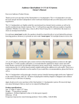
DJ System
PUSH FOR SETTINGS
50-60 Hz 110W
100-240VAC
SPEAKER CONTROL
INPUT
DIRECT OUT
INPUT
DIRECT OUT
HIGH-PASS OUT HIGH-PASS OUT
PUSH FOR SETTINGS
50-60 Hz 110W
100-240VAC
SPEAKER CONTROL
INPUT
DIRECT OUT
INPUT
DIRECT OUT
HIGH-PASS OUT HIGH-PASS OUT
PUSH FOR SETTINGS
SPEAKER CONTROL
SUBWOOFER HPF
DRM SUB
VAROFF
DRM
SUB
PUSH FOR SETTINGS
SPEAKER CONTROL
FLAT LIVE MUSIC
INSIDEMONCLUB
CLUB
SPEAKER VOICING
Hookup Diagrams continued…
Perhaps you’re a DJ playing bumpin’ tunes in the middle of the night to a crowd that’s groovin’ and dancin’
to your fine selection.
In this example, a laptop is connected to the inputs of two DRM8S subwoofers.
The High-Pass Out of each subwoofer is then connected to the input of each SRM22 | V-Class loudspeaker.
Additionally, a set of Mackie MC-250 headphones is connected to the phones jack of the laptop.
The Speaker Modes of both loudspeakers may be set to Club and the Subwoofer HPF set to DRM Sub.

SRM | V-Class High-Performance Powered Loudspeaker Series
8
SRM | V-Class High-Performance Powered Loudspeaker Series
Daisy-Chaining Multiple SRM | V-Class Loudspeakers
Hookup Diagrams continued…
CH1
CH2 CH3/4
PUSH FOR SETTINGS
MAXOFF
SPEAKER CONTROL
GAIN
LINE MIC
MAXOFF
U
LINE
MAXOFF
U
CH1
CH2 CH3/4
PUSH FOR SETTINGS
MAXOFF
SPEAKER CONTROL
GAIN
LINE MIC
MAXOFF
U
LINE
MAXOFF
U
CH1
CH2 CH3/4
PUSH FOR SETTINGS
MAXOFF
SPEAKER CONTROL
GAIN
LINE MIC
MAXOFF
U
LINE
MAXOFF
U
CH1
CH2 CH3/4
PUSH FOR SETTINGS
MAXOFF
SPEAKER CONTROL
GAIN
LINE MIC
MAXOFF
U
LINE
MAXOFF
U
USB 1-2
USB 3-4
MUTE
MUTE MUTE MUTE
MUTEMUTE MUTE
ProFX10v3 Mixer
To next
SRM | V-Class
loudspeaker
input
To next
SRM | V-Class
loudspeaker
input
Main
Outs
CH1
CH2 CH3/4
PUSH FOR SETTINGS
MAXOFF
SPEAKER CONTROL
GAIN
LINE MIC
MAXOFF
U
LINE
MAXOFF
U
CH1
CH2 CH3/4
PUSH FOR SETTINGS
MAXOFF
SPEAKER CONTROL
GAIN
LINE MIC
MAXOFF
U
LINE
MAXOFF
U
CH1
CH2 CH3/4
PUSH FOR SETTINGS
MAXOFF
SPEAKER CONTROL
GAIN
LINE MIC
MAXOFF
U
LINE
MAXOFF
U
To next
SRM | V-Class
loudspeaker
input
SRM | V-Class loudspeakers may be daisy-chained via the male XLR connector labeled “DIRECT OUT” (which sends
only the signal from the input located above it) or via the “MIX OUT” which outputs all inputs. Simply plug the signal
source (i.e., mixer output or microphone) into the input jack(s), and patch that loudspeaker’s direct out or mix out jack
to the next loudspeaker’s input jack, and so on, daisy-chaining multiple SRM | V-Class loudspeakers. See above for visual
representations of daisy-chaining.
NOTE: Make sure to set the gain knob(s) correctly. In the top diagram, input channel is set to “LINE” and in the bottom
diagram, input channel is set to “MIC”.

Owner’s Manual
9
Owner’s Manual
Large Club System
PUSH FOR SETTINGS
50-60 Hz 110W
100-240VAC
SPEAKER CONTROL
INPUT
DIRECT OUT
INPUT
DIRECT OUT
HIGH-PASS OUT HIGH-PASS OUT
PUSH FOR SETTINGS
50-60 Hz 110W
100-240VAC
SPEAKER CONTROL
INPUT
DIRECT OUT
INPUT
DIRECT OUT
HIGH-PASS OUT HIGH-PASS OUT
PUSH FOR SETTINGS
50-60 Hz 110W
100-240VAC
SPEAKER CONTROL
INPUT
DIRECT OUT
INPUT
DIRECT OUT
HIGH-PASS OUT HIGH-PASS OUT
PUSH FOR SETTINGS
50-60 Hz 110W
100-240VAC
SPEAKER CONTROL
INPUT
DIRECT OUT
INPUT
DIRECT OUT
HIGH-PASS OUT HIGH-PASS OUT
PUSH FOR SETTINGS
SPEAKER CONTROL
PUSH FOR SETTINGS
SPEAKER CONTROL
SUBWOOFER HPF
DRM SUB
VAROFF
DRM
SUB
FLAT LIVE MUSIC
INSIDEMONCLUB
LIVE
SPEAKER VOICING
PUSH FOR SETTINGS
SPEAKER CONTROL
FLAT LIVE MUSIC
INSIDEMONCLUB
LIVE
SPEAKER VOICING
Hookup Diagrams continued…
Here’s how to set up a large club system. In this example, the L/R outputs of a DL6S mixer are connected directly
to the channel inputs of a pair of DRM8S subwoofers. The Direct Out of each subwoofer is then connected to the inputs
of an additional pair of DRM8S subwoofers.
From here, the high-pass outputs of the two outer DRM8S subwoofers are connected directly to the inputs of a set
of SRM25 | V-Class loudspeakers. The Speaker Modes of these PA loudspeakers may be set to Live (or Club)
and the Subwoofer HPF set to DRM Sub. Talk about beefy low end!
Outputs and 2 from the mixer may be used as aux sends; these are connected directly to the channel inputs of a pair
of SRM25 | V-Class loudspeakers to be used as monitors for the band. The gain knob on all SRM25 | V-Class loudspeakers
in this example should be set to Line. The Speaker Modes of the monitor loudspeakers may be set to Monitor.

SRM | V-Class High-Performance Powered Loudspeaker Series
10
SRM | V-Class High-Performance Powered Loudspeaker Series
SRM | V-Class Loudspeakers: Rear Panel Features
SRM Connect App
SRM | V-Class loudspeakers are designed to be used
in conjunction with the SRM Connect App. With it, all
of the hardware features listed here – and more! – may
be controlled remotely via Bluetooth connection.
The only thing the SRM Connect App can’t do is turn
the loudspeaker on and o.
More information about the SRM Connect App may
be found by visiting the SRM Connect App Reference
Guide.
. Power Connection
This is a standard 3-prong IEC power connector.
Connect the detachable power cord (included in
the packaging with the loudspeaker) to the power
receptacle, and plug the other end of the power
cord into an AC outlet.
Make sure that the AC power is matched to
the AC power indicated on the rear panel
(above the IEC receptacle).
Disconnecting the plug’s ground pin is
dangerous. Don’t do it!
2. Power Switch
Press the top of this rocker switch inwards to turn
on the loudspeaker. Press the bottom of this rocker
switch inwards to turn o the loudspeaker.
As a general guide, the mixer (or other
signal source) should be turned on first,
subwoofers next, and loudspeakers last.
As such, the loudspeakers should also be turned
o first, followed by the subwoofers, then the mixer.
This will reduce the possibility of any turn-on or
turn-o thumps and other noises generated by any
upstream equipment from coming out of the speakers.
3. XLR and /4" Combo Inputs [Ch. and 2]
Input channels and 2 may accept a balanced
mic signal using an XLR connector. They are wired
as follows, according to standards specified by
the AES (Audio Engineering Society).
XLR Balanced Wiring:
Pin = Shield (ground)
Pin 2 = Positive (+ or hot)
Pin 3 = Negative (– or cold)
2
3
1
SHIELD
COLD
HOT
SHIELD
COLD
HOT
3
2
1
In addition to accepting a balanced mic signal
using an XLR connector, these input channels may
also accept /4" line-level signals driven by balanced
or unbalanced sources.
Channel 2 may also accept a Hi-Z source (such
as a guitar) via the /4" input without the need for
a separate DI box. Be sure to set the Ch. 2 In to Hi-Z in
the Configuration menu, though! Directions on page 8.
To connect balanced lines to these inputs, use
a /4" Tip-Ring-Sleeve (TRS) plug. “TRS” stands
for Tip-Ring-Sleeve, the three connection points
available on a stereo /4" or balanced phone jack
or plug. TRS jacks and plugs are used for balanced
signals and are wired as follows:
/4" TRS Balanced Mono Wiring:
Sleeve = Shield
Tip = Hot (+)
Ring = Cold (–)
SLEEVE
TIPSLEEVE
TIP
RING
RING
TIP
SLEEVERING
CH1
CH2 CH3/4
PUSH FOR SETTINGS
MAXOFF
SPEAKER CONTROL
GAIN
LINE MIC
MAXOFF
U
LINE
MAXOFF
U
2
3 6
4 7
5 8
109
1

Owner’s Manual
11
Owner’s Manual
SRM | V-Class Loudspeakers: Rear Panel Features continued...
To connect unbalanced lines to these inputs,
use a /4" mono (TS) phone plug, wired as follows:
/4" TS Unbalanced Mono Wiring:
Sleeve = Shield
Tip = Hot (+)
NEVER connect the output of an amplifier
directly to an SRM | V-Class input jack.
This could damage the input circuitry!
4. Gain [Ch. and 2]
The gain knobs adjust the input sensitivity
of the mic/line inputs. This allows signals from
the outside world to be adjusted to run through
each channel at optimal internal operating levels.
It ranges from o (knob fully down) up to max (knob
fully up).
If connecting mixer outputs to loudspeaker
inputs, set the gain knob to 0:00 [“LINE”]
for optimal sound and performance.
5. Direct Out [Ch. and 2]
This is a male XLR-type connector that produces
exactly the same signal that is connected to the input
jack located above it. Use it to daisy-chain several
SRM | V-Class loudspeakers together o the same
signal source(s).
They are wired as follows, according to standards
specified by the AES (Audio Engineering Society):
Balanced XLR Output Connector
Pin – Shield (ground)
Pin 2 – Positive (+ or hot)
Pin 3 – Negative (– or cold)
See page 8 to learn more about daisy-chaining
SRM | V-Class loudspeakers.
SLEEVE
TIP
TIPSLEEVE
TIP
SLEEVE
2
1
SHIELD
COLD
HOT
3
SHIELD
COLD
HOT
3
2
1
6. /8" Input [Ch. 3/4]
This input may accept a stereo /8" line-level signal
from a phone, tablet, MP3 player, or other signal
source.
NEVER connect the output of an amplifier
directly to an SRM | V-Class input jack.
This could damage the input circuitry!
7. Gain [Ch. 3/4]
This gain knob adjusts the input sensitivity
of the /8" stereo input. This allows signals from
the outside world to be adjusted to run at optimal
internal operating levels. It ranges from o (knob
fully down) up to max (knob fully up).
8. Mix Out
This is a male XLR-type connector that produces
the post-DSP mix – afer voicing mode and EQ, but
before the alignment delay – from all three input jacks
(with Ch. 3/4 mono-summed). Use it to daisy-chain
several SRM | V-Class loudspeakers together o the
same signal source(s).
It is wired the same as the direct outputs as seen
to the lef.
9. LCD Display
This modern, high-resolution, all-color TFT
LCD Display is one of the most vital features
of the SRM | V-Class loudspeaker. It displays
loudspeaker information including (but not limited
to) levels, EQ, selected voicing, settings, lock / unlock
status and other parameters.
The brightness is controllable (hi, dim, o),
but it must be set to hi or dim for certain
aspects of the set-up options.
0. Speaker Control Knob
This push-button rotary encoder allows you to access
functions such as channel and master level control
and metering, application specific voicings & EQ, setup
functions, product information and much more!
PUSH FOR SETTINGS
SPEAKER CONTROL
1 2 BT Main
109

SRM | V-Class High-Performance Powered Loudspeaker Series
12
SRM | V-Class High-Performance Powered Loudspeaker Series
SRM Mix Control™
The following list provides the high level navigation
items, in order, on the user interface and their
subsequent user controlled parameters.
The default screen is the mixer view, as seen below:
Mixer – This displays the I/O levels
and metering, EQ settings, HPF levels
and more. These may all be changed here.
Menu – The menu provides icon selectors
for all user-controllable functions with most
of these containing an array of sub-menus.
The menu is accessed by rotating the speaker
control knob clockwise until the menu icon
is illuminated in a can’t-miss DayGlo green;
then press again to open the menu.
We will go through each, how to get there and how
to change settings.
Afer a selection is made, the LCD screen will
revert back to the Mixer screen afer a short period
of (speaker control) inactivity. You yourself may
continue to be as active (or inactive)as you want.
Rotate the speaker control knob to navigate between
the selections and push the button to open and edit
the parameters.
1 2 BT –1.0
Mixer
Delay
Mode
Bluetooth
Sub
Config
MIXER MODE SUB
DELAY
CONFIG
BT
Mixer
As mentioned earlier, the default screen is the mixer
view. And the default selection is the output level.
From here, simply rotate the speaker control knob
clockwise (louder) or counter-clockwise (quieter).
The top row selections change the levels of input
channels , 2 and BT and the Main output. Notice below
how each parameter illuminates as the speaker control
knob is rotated to the right from channel to 2,
Bluetooth (BT) and the Main output last.
In order to change the level, push the speaker
control knob when the desired channel is illuminated.
In the example below, notice how the channel 2 fader
has been moved to the –4 dB mark. Once the level
you desire has been dialed in, press the speaker
control knob again to return to the mixer screen.
The level control ranges are as follows:
• Channels and 2: – (o) to “U” (unity)
• Bluetooth: – (o) to “U” (unity)
• Main Output: – (o) to “U” (unity)
1 2 BT –1.0
1 2 BT Main
1 2 BT Main
1 2 BT Main
1 2 BT Main
1 –14 BT Main

Owner’s Manual
13
Owner’s Manual
All four may also be muted (via the SRM
Connect app). Red fader caps indicate
a muted channel, while white fader caps
indicate unmuted channels. A muted
channel will unmute once a level is changed
via the speaker control knob (or SRM Connect).
Let’s expand on the meters for a moment. The peak
holder meter peaks at +6 dBu and a 4: compressor
engages at approximately +8 dBu. This means that
the loudspeaker is compressing when the peak/hold
indicator is hitting the top of the meter scale. It also
signifies that you are nearing the end of available
headroom. As you continue to raise the volume,
you’re continuing to compress the signal, as well.
This is reflected in compression of the metering – which
will remain at or near the top of the meter strip – and
reflected in the acoustic output.
In addition to raising and lowering the input
and output levels, the mixer view is where to adjust
the EQ parameters and access the Menu screen, too.
These icons are located underneath each meter.
In order to change a channel’s EQ, push the speaker
control knob when the desired channel’s EQ icon
is illuminated.
Next, push the speaker control knob again once
the EQ you want to change is illuminated. See below.
1 2 BT Main 1 2 BT Main
1 2 BT Main 1 2 BT Main
1
High 0dB
Mid 0dB
Low 0dB
HPF 20Hz
1
High 0dB
Mid 0dB
Low 0dB
HPF 20Hz
1
High 0dB
Mid 0dB
Low 0dB
HPF 20Hz
1
High 0dB
Mid 0dB
Low 0dB
HPF 20Hz
The EQ ranges are as follows:
• High: ±2 dB @ 5 kHz
• Mid: ±2 dB @ 2.5 kHz
• Low: ±2 dB @ 80 Hz
• HPF: 80 Hz – 50 Hz @ 2 dB per octave
[Channels and 2 only]
As seen below, we changed the channel high,
mid and low EQ to +5 and the HPF setting to 0 Hz.
Press the speaker control knob to return to the
previous screen once the EQ settings you desire
have been dialed in.
In addition to the four EQ choices shown above,
there’s a fifh and final selection: the lef-facing arrow.
Illuminating and selecting this simply returns you
to the main mixer screen.
Other than the aforementioned EQ settings screen,
this is also where to access the menu screen. From
the mixer screen, simply rotate the speaker control
knob right until the bottom right icon is illuminated (A).
Then push the knob to enter the menu screen (B).
Let’s take a look and see what the menu screen does.
The first step is to flip the page!
1
Mid 0dB
Low 0dB
HPF 20Hz
High +5
1
Low 0dB
HPF 20Hz
High 0dB
Mid +5
1
Mid 0dB
HPF 20Hz
Low +5
1
Mid 0dB
Low 0dB
HPF 110Hz
High 0dB High 0dB
1
High 0dB
Mid 0dB
Low 0dB
HPF 20Hz
1 2 BT Main
MIXER MODE SUB
DELAY
CONFIG
BT
(A) (B)

SRM | V-Class High-Performance Powered Loudspeaker Series
14
SRM | V-Class High-Performance Powered Loudspeaker Series
Menu Screen
The menu screen displays six icons. Like the
mixer screen, just rotate the speaker control knob
until the icon of the parameter you want to change
is illuminated. Then push the knob to enter that icon’s
screen.
The six icon selectors are as follows:
• Mixer
• Speaker Mode
• Sub
• Delay
• Bluetooth
• Configuration
We’ll go through each one, starting with mixer
at the top lef.
Mixer
This is the easiest to describe since we just went
through the mixer screen on the last two pages!
To recap, though, the mixer screen is where
to set levels and channel EQ.
Speaker Mode
Speaker mode allows you to change
the loudspeaker’s speaker voicing to tailor
it to best suit your particular application.
Once speaker mode is illuminated push in
the speaker control knob to enter and update.
MIXER MODE SUB
DELAY
CONFIG
BT
SUB
DELAY
CONFIG
BT
MODE
MAIN
The view will look somewhat similar to this:
There are five speaker modes, plus an additional
choice of inside or outside use. That is essentially TEN
speaker voicing modes to choose from! Let’s check
them out:
• Flat – No question about this speaker mode;
it’s flat! This plug-and-play mode is perfect
for singer-songwriters and listening to mastered music.
• Live – This mode features a low frequency
roll-o to get rid of unwanted thumps and adds
boost and sparkle to mid-range and high frequencies.
• Speech – This mode features a significant low
frequency roll-o to get rid of unwanted thumps.
It also adds boost and sparkle to mid-range and high
frequencies, critical for speech applications. Lastly,
a compressor has been added to help control spoken
audio levels. This plug-and-play mode is perfect for
larger venue applications where speech is the primary
audio source in need of clear and precise intelligibility.
• Club – This mode is full range, but focuses
on increased bass and brilliant high frequencies.
This is the place to start for most DJ / music
playback applications.
• Monitor – Monitor mode was designed primarily to
remove unwanted low frequency buildup while also
improving mid-range articulation for the artist(s).
This mode should only be engaged when
the speaker is in its monitor orientation
and coupled with a stage or other hardwood
floor... if not, the speaker won’t sound right.
About that inside / outside selection... in a sentence,
choose whether you are using the loudspeaker inside
or outside. The speaker’s voicing is altered to the
environment. That’s all you need to know, but we’re
going to give you more!
When speakers are outside, a combination of low
and high frequencies don’t build up the way they
do inside. SRM | V-Class corrects for that by
boosting the frequency ranges that become deficient
so the speaker sounds the same outside as when
it’s inside. You make the selection, we’ll do the rest!
Simply rotate the speaker control knob until
the speaker mode you desire is illuminated, then
push to select it. As seen above, we selected Live Inside.
FLAT LIVE SPEECH
LOCATION
INSIDE
MONCLUB
LIVE
SPEAKER VOICING

Owner’s Manual
15
Owner’s Manual
In addition to all of the speaker mode choices, there’s
a final selection: the lef-facing arrow. Illuminating
and selecting this simply returns you to the menu.
Refer to the Frequency Response graphs on
pages 28 and 29 for further information.
Sub
Afer pushing the speaker control knob in to select
sub, you will be presented with a multitude of choices,
including:
• O – Choose this if there is no subwoofer
connected to the system. Here you are using
SRM | V-Class loudspeakers only.
• DRM Sub – Choose this if a Mackie DRM8S
subwoofer is connected to the system. The crossover
point is set to 90 Hz to work in perfect harmony with
the Mackie DRM8S Sub. This is what we hope you
choose, thank you for your support!
• Var – Choose this if a non-Mackie DRM8S
subwoofer is connected to the system. Here you
can select the subwoofer’s HPF, ranging from
40 Hz – 60 Hz.
Rotate the speaker control knob until the sub HPF
you desire is illuminated, then push to select it.
If var is selected (as seen below), the frequency
is illuminated and may be changed by rotating the
speaker control knob clockwise (raise the frequency)
and counter-clockwise (lower the frequency).
DELAY
CONFIG
BT
MAIN
MODE
SUB
CROSSOVER
90Hz
Variable
Mix Out
FULL
RANGE
VAR
OFF
DRM
SUB
CROSSOVER
Variable
Mix Out
FULL
RANGE
VAR
OFF
DRM
SUB
90Hz
Also available is a mix out mode. The mix out mode
allows you to select if the signal passes all frequencies
(Full Range) or only the low frequencies (Low Pass)
out of the mix out jack, acting as a fixed or variable
system crossover for full range systems where
the audio is routed first through the V-Class,
and then to the sub. Push the speaker control knob
in and release to switch between the two mix out
mode selections. Release when the one you desire
is illuminated, then leave it be.
• Full Range – Selecting full range does not filter
any frequencies, thereby sending the “full range”
of frequencies, hence the name! This is typically
preferred when connected to another loudspeaker.
• Low Pass – Selecting low pass essentially cuts
out the high frequencies. This allows the subwoofer
to do the majority of the “heavy lifing” on the lower
frequencies, dependent on where the crossover is set.
As such, this is typically selected when connected
to a subwoofer.
Mix out mode is not available when
the Subwoofer HPF is set to o.
In addition to the sub modes, there’s a fourth
and final selection: the lef-facing arrow. Illuminating
and selecting this simply returns you to the menu.
Delay
Probably the easiest parameter to describe
and update. This controls the monitor delay.
In other words, you are going to want to time-align
the speakers throughout the venue so the sound
hits everywhere simultaneously. This is the place.
The delay time ranges from a low of 0.0 ms (f, m)
to a maximum of 00 ms (2.5 f, 34.2 m).
CROSSOVER
90Hz
Variable
Mix Out
FULL
RANGE
VAR
OFF
DRM
SUB
CONFIG
BT
MAIN
MODE SUB
DELAY

SRM | V-Class High-Performance Powered Loudspeaker Series
16
SRM | V-Class High-Performance Powered Loudspeaker Series
In order to change the delay, first push the speaker
control knob when the delay icon is illuminated (see
image above). This opens the delay view.
From here, rotate the speaker control knob clockwise
until the ms parameter is highlighted.
This is the only parameter that can
be changed here; the f and m delay time
ranges update automatically dependent
on where ms is set.
Push the speaker control knob in to select
the ms parameter followed by rotating the speaker
control knob clockwise (raise the delay time )
and counter-clockwise (lower the delay time).
Like the previous sub-menus, the delay also
has a lef-facing arrow. Illuminating and selecting
this simply returns you to the menu.
DELAY
ms
9
ft
10.1
m
3.0
DELAY
ms
9
ft
10.1
m
3.0
Bluetooth
This is where to set up and view wireless connectivity
options for the devices and speakers.
Below is a list of the parameters that may be edited:
Device – The device may either be paired or not
paired.
To pair:
() Make sure “PAIR” is illuminated and push
the speaker control knob.
(2) The text “NOT PAIRED” will change
to “DISCOVERABLE” and “PAIR” will change
to “CANCEL”. From here, you can either
(A) turn the device and device’s bluetooth
on to pair, or (B) push the speaker control
knob to cancel the action.
(3) The text “DISCOVERABLE” will change
to “PAIRED” and “CANCEL” will change
to “DISCONNECT”. From here, you can either
(A) use the device and SRM Connect app
to control the loudspeakers, or (B) push
the speaker control knob to disconnect.
CONFIG
MAIN
MODE SUB
DELAY
BT
NOT PAIRED
PAIR
NOT LINKED
CONNECT
BT MODE: STEREO
CHANNEL: LEFT
DISCOVERABLE
CANCEL
NOT LINKED
CONNECT
BT MODE: STEREO
CHANNEL: LEFT
PAIRED
DISCONNECT
NOT LINKED
CONNECT
BT MODE: STEREO
CHANNEL: LEFT

Owner’s Manual
17
Owner’s Manual
Notice how the icon of the device also illuminates
when paired.
The Bluetooth connection may disconnect
when aected by electrostatic discharge
(ESD) or electrical fast transients (EFT).
If this occurs, manually reconnect the
Bluetooth connection.
SRM | V-Class Loudspeaker – The loudspeaker may
either be linked or not linked. Additionally, this
is where to select the bluetooth mode [zone
or stereo]. Lastly, if the bluetooth mode is stereo,
you may select which loudspeaker is located
on the lef and which is on the right.
To link:
The steps to link speakers is quite similar
to that of pairing a device: () Make sure “connect”
is illuminated and push the speaker control knob.
(2) The text “NOT LINKED” will change
to “SEARCHING...” and “CONNECT” will change
to “CANCEL”. From here, you can either (A) turn
the other SRM | V-Class loudspeaker on and follow
these same steps to link, or (B) push the speaker
control knob to cancel the action.
(3) The text “SEARCHING...” will change to
“PRIMARY” on one loudspeaker and “SECONDARY”
on the other. Also, “CANCEL” will change
to “DISCONNECT”. From here, you can either
(A) select a Bluetooth mode (info to the right), or
(B) push the speaker control knob to disconnect.
NOT LINKED
CONNECT
BT MODE: STEREO
PAIRED
DISCONNECT
CHANNEL: LEFT
PAIRED
DISCONNECT
SEARCHING...
CANCEL
BT MODE: STEREO
CHANNEL: LEFT
PAIRED
DISCONNECT
PRIMARY
DISCONNECT
BT MODE: STEREO
CHANNEL: LEFT
NOT PAIRED
PAIR
SECONDARY
DISCONNECT
BT MODE: STEREO
CHANNEL: LEFT
Notice how the icon of the loudspeaker also
illuminates when linked.
BT Mode – This is where to select the bluetooth
mode [zone or stereo]. Rotate the speaker control
knob until BT mode is illuminated then push it to
switch between BT modes.
So what’s the dierence? Let’s take a look!
STEREO: The stereo setting is your default two
loudspeaker setup, ideal for applications such
as a party, DJ, etc., where a device is paired
and streaming music in stereo. Here the main
level controls both speakers.
The following channels are available when
the SRM | V-Class loudspeakers are linked in stereo:
• Ch. Primary or Secondary
• Ch. 2 Primary or Secondary
• Bluetooth
• Stereo Main
If the bluetooth mode is set to stereo, you may select
which loudspeaker is located on the lef and which
is on the right. Simply rotate the speaker control
knob so that channel is illuminated, then push
it to switch between lef and right.
PAIRED
DISCONNECT
PRIMARY
DISCONNECT
BT MODE: STEREO
CHANNEL: LEFT
PAIRED
DISCONNECT
PRIMARY
DISCONNECT
BT MODE: STEREO
LEFT
CHANNEL:

SRM | V-Class High-Performance Powered Loudspeaker Series
18
SRM | V-Class High-Performance Powered Loudspeaker Series
ZONE: The zone mode setting is your optional
loudspeaker setup, ideal for when the speakers
are placed in dierent locations and allows for
separate main level controls.
SRM | V-Class loudspeakers in zone mode
setting will receive a mono-summed signal.
The following channels are available when the
SRM | V-Class loudspeakers are linked in zone mode:
• Ch. Primary or Secondary
• Ch. 2 Primary or Secondary
• Bluetooth Primary or Secondary
• Primary or Secondary Main
As before, illuminating and selecting the lef-facing
arrow returns you to the previous screen.
Configuration
This is where to select the Ch. and 2 input settings,
front LED status and color, LCD brightness, lock access
to the settings, auto connect / link bluetooth and more.
This is similar to what you will see afer first entering
the configuration screen. The current selection of the
top five features will be illuminated.
To change a setting, just rotate the speaker
control knob until the configuration you desire
to change is illuminated, then push to select it.
MODE SUB
DELAY
BT
MIXER
CONFIG
CONFIGURATION
CH1 IN
ABOUT/RES...
FRONT LED
CH2 IN
LED COLOR
LCD SCREEN
BT SETTINGS...
LOCK...
LINE MIC
HI DIM OFF
GRN WH MUL
ON OFF SIG
LINE HI-Z
These are the choices from top to bottom:
Ch 1 in – As mentioned a few pages back, the channel
input accepts both XLR and /4" inputs. In addition
to setting each channel’s gain knob to the correct
setting, be sure to set it here, as well. The selection
will illuminate green; line on the lef, mic on the right.
Illuminating and selecting the lef-facing arrow
returns you to the previous screen.
More information about the channel inputs
may be found on pages 0-.
Ch 2 in – In addition to the previously mentioned
channel input, the channel 2 input allows
instruments to be connected directly into the /4" jack.
To connect an instrument directly without using a DI
Box, set channel 2’s gain knob to Hi-Z and change
the channel 2 input setting to Hi-Z. The Hi-Z text will
illuminate to indicate that Hi-Z is active. Next connect
the output from the instrument to the channel 2 /4"
input. The input impedance is optimized for direct
connection and high-frequency fidelity is assured.
Guitars may sound dull and muddy without a DI
box or if Hi-Z is not engaged. When not set at Hi-Z,
the channel 2 /4" input become a line input, as seen
below.
Illuminating and selecting the lef-facing arrow
returns you to the previous screen.
More information about the channel inputs
may be found on pages 0-.
CONFIGURATION
ABOUT/RES...
FRONT LED
CH2 IN
LED COLOR
LCD SCREEN
BT SETTINGS...
LOCK...
HI DIM OFF
GRN WH MUL
ON OFF SIG
LINE HI-Z
CH1 IN LINE MIC
CONFIGURATION
ABOUT/RES...
FRONT LED
LED COLOR
LCD SCREEN
BT SETTINGS...
LOCK...
HI DIM OFF
GRN WH MUL
ON OFF SIG
CH1 IN LINE MIC
CH2 IN LINE HI-Z

Owner’s Manual
19
Owner’s Manual
Front LED Mode – There are two horizontal LED
bars on the front of each SRM | V-Class loudspeaker. One
bar is located near the bottom and the other near the top.
Here is where you decide if you want the front LED
on, o or sig. When illuminated, push the speaker
control knob to select between the three choices.
The three front LED modes are as follows:
• On [Default] – The LEDs illuminate in all their
glory.
• Signal – The LEDs illuminate when there is signal
at the outputs.
• O – The LEDs do not illuminate; they are turned
o and SRM | V-Class is in ‘stealth’ mode.
Like the previous sub-menus, configuration also
has a lef-facing arrow. Illuminating and selecting
this simply returns you to the menu.
LED Color – Here is where you decide what color
you want the front color LED. When illuminated,
push the speaker control knob to select between
the three choices.
The three LED colors to choose from are:
• Green [Default] – The LEDs illuminate green.
• White – The LEDs illuminate... you guessed it.
White!
• Multi-color – The LEDs switch between green,
white and o in five second intervals. This
is typically used in retail situations, but feel
free to use it yourself!
Multi-color may only be selected if the front
LED mode is set to on. It will not work if set
to signal or o.
Illuminating and selecting the lef-facing arrow
returns you to the previous screen.
CONFIGURATION
ABOUT/RES...
LED COLOR
LCD SCREEN
BT SETTINGS...
LOCK...
HI DIM OFF
GRN WH MUL
ON OFF SIG
CH1 IN LINE MIC
CH2 IN LINE HI-Z
FRONT LED
CONFIGURATION
ABOUT/RES...
LCD SCREEN
BT SETTINGS...
LOCK...
HI DIM OFF
GRN WH MUL
ON OFF SIG
CH1 IN LINE MIC
CH2 IN LINE HI-Z
FRONT LED
LED COLOR
LCD Screen – The fifh configuration setting
that may be changed is the brightness – or lack
thereof – of the LCD screen.
There are three choices: hi, dim and o.
Hi or dim LCD screen brightness is required
for certain aspects of the set-up options.
Illuminating and selecting the lef-facing arrow
returns you to the previous screen.
Lock... – This is where to lock and unlock the
interface with a secret 4-digit numeric password.
Locking – Push the speaker control knob to enter
lock mode. From here, rotate the speaker control
knob until the first number you desire is illuminated
and press to select. Follow the same procedure
for the next three numbers.
As seen below, we decided to go with -9-8-4
because we’re “fans” of George Orwell.
Notice how “lock” appears and is illuminated.
Push the knob again to confirm the lock.
No further changes may be made until the control
access is unlocked.
CONFIGURATION
ABOUT/RES...
BT SETTINGS...
LOCK...
HI DIM OFF
ON OFF SIG
CH1 IN LINE MIC
CH2 IN LINE HI-Z
FRONT LED
LED COLOR
LCD SCREEN
GRN WH MUL
CONFIGURATION
ABOUT/RES...
BT SETTINGS...
HI DIM OFF
ON OFF SIG
CH1 IN LINE MIC
CH2 IN LINE HI-Z
FRONT LED
LED COLOR
LCD SCREEN
GRN WH MUL
LOCK...
CONTROL ACCESS
DEL
1 2
1
3 4 5 6 7 8 9 0
89 4
LOCK

SRM | V-Class High-Performance Powered Loudspeaker Series
20
SRM | V-Class High-Performance Powered Loudspeaker Series
Unlocking – In order to unlock the loudspeaker,
simply press the speaker control knob and you
will be routed directly to the lock screen in
the control access section. Here you will need
to re-enter the 4-digit code and push the speaker
control knob to unlock.
Secret Squirrel Unlock – If you – or worse, someone
else! – set up a 4-digit lock code and you don’t know
the passcode, there is a quick fix. Simply press
and hold down the speaker control knob down
for a few seconds and it will automatically unlock.
Del, of course, deletes the previous selected number
in case you made an oopsie. Speaking of oopsies, forget
George Orwell, right?! We should have gone with Prince
(999) or Rush (22) instead! Del is available whether
locking or unlocking.
Illuminating and selecting the lef-facing arrow
returns you to the previous screen.
BT Settings – This is where the Bluetooth
configuration settings (auto-connect, auto-link) live.
This is similar to what you will see afer first entering
the BT settings screen.
Auto Conn – Allows a previously paired device
to auto reconnect if both the device and speaker
are powered on and in range. When illuminated,
push the speaker control knob to select between
on or o.
Auto Link BT – Allows two previously paired speakers
to automatically re-link if both are powered on
and in range. When illuminated, push the speaker
control knob to select between primary, secondary
or o.
CONFIGURATION
ABOUT/RES...
HI DIM OFF
ON OFF SIG
CH1 IN LINE MIC
CH2 IN LINE HI-Z
FRONT LED
LED COLOR
LCD SCREEN
GRN WH MUL
LOCK...
BT SETTINGS...
BT CONFIGURATION
SEC PRI OFF
ON OFFAUTO-CONN
AUTO-LINK
For obvious reasons, you cannot have two primary –
or two secondary, for that matter – loudspeakers.
Once a selection is made on one loudspeaker, the
other loudspeaker will default to the other choice.
A Bluetooth-paired device may be
connected to a primary or secondary
loudspeaker. That said, we suggest
pairing to the primary loudspeaker.
Illuminating and selecting the lef-facing arrow
returns you to the previous screen.
About/Res... – This displays the current information
about your loudspeaker.
There are really only two reasons to ever go here:
() If you’ve been instructed to do so by Technical
Support; have this information handy!
(2) If you need to do a factory reset
on the loudspeaker.
This is similar to what you will see afer first entering
the About/Res settings screen.
The first two items display the loudspeaker’s
firmware and DSP versions and the third is
the temperature of the loudspeaker. None of these
are editable, but they could come in handy if you
need to talk to someone in Technical Support.
CONFIGURATION
HI DIM OFF
ON OFF SIG
CH1 IN LINE MIC
CH2 IN LINE HI-Z
FRONT LED
LED COLOR
LCD SCREEN
GRN WH MUL
LOCK...
BT SETTINGS...
ABOUT/RES...
ABOUT / RESET
30.4 C / 86.8 F
1.1.1.600
Model : SRM210
FW : 1.0.172
DSP :
1.35BT :
TEMP :
FACTORY RESET...
/