Page is loading ...

OWNER’S MANUAL
1600W POWERED LOUDSPEAKERS
SRM550 • SRM650 • SRM750

SRM550 • SRM650 • SRM750 Powered Loudspeakers
2
SRM550 • SRM650 • SRM750 Powered Loudspeakers
1. Read these instructions.
2. Keep these instructions.
3. Heed all warnings.
4. Follow all instructions.
5. Do not use this apparatus near water.
6. Clean only with a dry cloth.
7. Do not block any ventilation openings. Install in accordance with the manu-
facturer’s instructions.
8. Do not install near any heat sources such as radiators, heat registers, stoves,
or other apparatus (including amplifiers) that produce heat.
9. Do not defeat the safety purpose of the polarized or grounding-type plug.
A polarized plug has two blades with one wider than the other. A grounding-
type plug has two blades and a third grounding prong. The wide blade or
the third prong are provided for your safety. If the provided plug does not fit
into your outlet, consult an electrician for replacement of the obsolete outlet.
10.
Protect the power cord from being walked on or pinched particularly at plugs,
convenience receptacles, and the point where they exit from the apparatus.
11.
Only use attachments/accessories specified by the manufacturer.
12.
Use only with a cart, stand, tripod, bracket, or table
specified by the manufacturer, or sold with the
apparatus. When a cart is used, use caution when
moving the cart/apparatus combination to avoid injury
from tip-over.
13.
Unplug this apparatus during lightning storms or when
unused for long periods of time.
14.
Refer all servicing to qualified service personnel. Servicing is required when
the apparatus has been damaged in any way, such as power-supply cord
or plug is damaged, liquid has been spilled or objects have fallen into the
apparatus, the apparatus has been exposed to rain or moisture, does not
operate normally, or has been dropped.
15.
This apparatus shall not be exposed to dripping or splashing, and no object
filled with liquids, such as vases or beer glasses, shall be placed on the
apparatus.
16.
Do not overload wall outlets and extension cords as this can result in a risk
of fire or electric shock.
17.
This apparatus has been designed with Class-I construction and must be
connected to a mains socket outlet with a protective earthing connection
(the third grounding prong).
18.
This apparatus has been equipped with a rocker-style AC mains power
switch. This switch is located on the rear panel and should remain readily
accessible to the user.
PORTABLE CART
WARNING
CAUTION
The lightning flash with arrowhead symbol within
an equilateral triangle is intended to alert the user
to the prescence of uninsulated “dangerous voltage”
within the product’s enclosure, that may be of significant
magnitude to constitute a risk of electric shock to persons.
RISK OF ELECTRIC SHOCK! DO NOT OPEN!
CAUTION: TO REDUCE THE RISK OF ELECTRIC SHOCK DO NOT
REMOVE COVER (OR BACK). NO USER-SERVICEABLE PARTS INSIDE.
REFER SERVICING TO QUALIFIED PERSONNEL.
The exclamation point within an equilateral triangle is
intended to alert the user of the presence of important
operating and maintaining (servicing) instructions in the
literature accompanying the appliance.
Laite on liitettävä suojakoskettimilla varustettuun pistorasiaan.
Apparatet må tilkoples jordet stikkontakt.
Apparaten skall anslutas till jordat uttag.
19.
The MAINS plug or an appliance coupler is used as the disconnect device,
so the disconnect device shall remain readily operable.
20. NOTE: This equipment has been tested and found to comply with
the limits for a Class B digital device, pursuant to part 15 of the FCC
Rules. These limits are designed to provide reasonable protection
against harmful interference in a residential installation. This equipment
generates, uses, and can radiate radio frequency energy and, if not
installed and used in accordance with the instructions, may cause
harmful interference to radio communications. However, there is no
guarantee that interference will not occur in a particular installation.
If this equipment does cause harmful interference to radio or television
reception, which can be determined by turning the equipment off and
on, the user is encouraged to try to correct the interference by one or
more of the following measures:
• Reorientorrelocatethereceivingantenna.
• Increasetheseparationbetweentheequipmentandthereceiver.
• Connecttheequipmentintoanoutletonacircuitdifferentfromthat
to which the receiver is connected.
• Consultthedealeroranexperiencedradio/TVtechnicianforhelp.
CAUTION: Changes or modifications to this device not expressly approved
by LOUD Technologies Inc. could void the user's authority to operate the
equipment under FCC rules.
21.
This apparatus does not exceed the Class A/Class B (whichever is
applicable)
limits for radio noise emissions from digital apparatus as
set
out in the radio interference regulations of the Canadian Department
of
Communications.
ATTENTION —
Le présent appareil numérique n’émet pas de bruits radioélec-
triques dépassant las limites applicables aux appareils numériques de class
A/de class B (selon le cas) prescrites dans le réglement sur le brouillage
radioélectrique édicté par les ministere des communications du Canada.
22.
Exposure to extremely high noise levels may cause permanent hearing
loss. Individuals vary considerably in susceptibility to noise-induced hearing
loss, but nearly everyone will lose some hearing if exposed to sufficiently
intense noise for a period of time. The U.S. Government’s Occupational
Safety and Health Administration (OSHA) has specified the permissible
noise level exposures shown in the following chart.
According to OSHA, any exposure in excess of these permissible limits
could result in some hearing loss. To ensure against potentially dangerous
exposure to high sound pressure levels, it is recommended that all persons
exposed to equipment capable of producing high sound pressure levels
use hearing protectors while the equipment is in operation. Ear plugs or
protectors in the ear canals or over the ears must be worn when operating
the equipment in order to prevent permanent hearing loss if exposure is in
excess of the limits set forth here:
Duration, per
day in hours
Sound Level dBA,
Slow Response
Typical Example
8 90 Duo in small club
6 92
4 95 Subway Train
3 97
2 100 Veryloudclassicalmusic
1.5 102
1 105 John screaming at Troy about deadlines
0.5 110
0.25 or less 115 Loudest parts at a rock concert
WARNING — To reduce the risk of fire or electric shock,
do not expose this apparatus to rain or moisture.
CAUTION — To prevent electric shock hazard, do not connect
to mains power supply while grille is removed.
Correct disposal of this product: This symbol indicates that this product should not be disposed of with your household
waste, according to the WEEE directive (2012/19/EU) and your national law. This product should be handed over to
an authorized collection site for recycling waste electrical and electronic equipment (EEE). Improper handling of this type
of waste could have a possible negative impact on the environment and human health due to potentially hazardous substances
that are generally associated with EEE. At the same time, your cooperation in the correct disposal of this product will
contribute to the effective usage of natural resources. For more information about where you can drop off your waste
equipment for recycling, please contact your local city office, waste authority, or your household waste disposal service.
Important Safety Instructions

Owner’s Manual
3
Owner’s Manual
Contents Features
Part No. SW0985 Rev. B 07/14
©2014 LOUD Technologies Inc. All Rights Reserved.
• 1600Wsystempowerpairedwithcustom
transducersdelivergig-levelvolumeswith
roomtospare
• 12"high-outputLFdriver/1.4"titaniumdome
compressiondriver[SRM550]
• 15"high-outputLFdriver/1.4"titaniumdome
compressiondriver[SRM650]
• 2x15"high-outputLFdriver/1.4"titanium
domecompressiondriver[SRM750]
• “Built-Like-A-Tank”all-wood,internally
bracedcabinetdeliversprofessional-grade
road-worthiness
• Rugged18-gaugesteelgrilleandne-textured,
sleekblackcabinetnish
• Frontportedformaximumlow-endextension
andpunch
• High-DenitionAudioProcessingforprofessional
soundwithunmatchedclarity
• Patentedacousticcorrectiondevelopedwith
touringgeniusesatEAW
®
• Precision2-waydigitalcrossover
• Drivertimealignmentandphasecorrection
• Quickone-buttonSpeakerModeselection
forapplication-specicvoicing(PA,DJ,Monitor,
Soloist,FillandSpeech)
• Effortlesslyeliminatenastyfeedbackwith
one-buttonautomaticFeedbackDestroyer
• Integrated2-channelmixerfeaturingdual
Wide-Z
™
inputs
• Handlesanythingfrommicstoguitarsto
mixerswithasingletwistofthegainknob
• IncludesstereoRCAinputsforeasyconnection
tomusicsource
• Perfectforthesinger/songwriter,
pluginandleavethemixerathome
• SmartProtect
™
DSPkicksintoprotect
yourinvestmentwhenthingsgetpushed
alittletoohard
• FlyableviastandardM10eyebolts
• Monitor-specic60˚angleandvoicing
modeperfectforcuttingthroughonstage
[SRM550/SRM650]
Like us
Follow us
Watch our dang videos
Important Safety Instructions .................................. 2
Contents ................................................................. 3
Features ................................................................. 3
Introduction ............................................................ 4
How To Use This Manual ......................................... 4
Getting Started ....................................................... 4
Things To Remember ................................................ 4
Hookup Diagrams .................................................... 5
SRM Loudspeaker: Rear Panel Features .................... 9
1. Power Connection ......................................... 9
2. Power Switch ............................................... 9
3. XLR and 1/4" Combo Inputs .......................... 9
4. Gain Knobs ................................................. 10
5. RCA Inputs [Channel 2 Only] ....................... 10
6. Thru Output ................................................ 11
7. Ch 1/Mix Switch [Thru Output] ................... 11
8. Speaker Mode ............................................ 11
9. Feedback desTROYer ................................... 11
10. Main Logo Switch / Limit LED .................... 12
11. Extra Knobs, Buttons and LEDs .................. 12
12. Rock ‘n Roll .............................................. 12
Smart Protect ....................................................... 13
Limiting .......................................................... 13
Overexcursion Protection ................................ 13
Thermal Protection .......................................... 13
AC Power ............................................................. 13
Care and Maintenance ........................................... 13
Placement ............................................................. 14
Room Acoustics ............................................... 15
Rigging ............................................................... 16
Rigging Design Practices .................................. 16
Rigging Hardware and Accessories ................... 16
Rigging Notes ................................................. 16
Important Rigging Reminder ............................ 17
Appendix A: Service Information ............................ 18
Appendix B: Connections ....................................... 20
Appendix C: Technical Information .......................... 21
SRM550 Dimensions & Frequency Response ..... 23
SRM650 Dimensions & Frequency Response ..... 24
SRM750 Dimensions & Frequency Response ..... 25
SRM Loudspeaker Block Diagram ..................... 26
Limited Warranty .................................................. 27

SRM550 • SRM650 • SRM750 Powered Loudspeakers
4
SRM550 • SRM650 • SRM750 Powered Loudspeakers
Getting Started
Introduction
SRM1600WHigh-DenitionPowered
LoudspeakersdeliveranewlevelofSRMruggedness,
clarityandsimplicitywithunmatchedbassresponse.
Hugesystempowerispairedwithcustomtransducers
withinprofessional-grade,internally-bracedall-wood
cabinetsthatare“Built-Like-A-Tank”.
TheseSRMloudspeakersfeatureourHighDenition
AudioProcessing
™
,includingpatentedacoustic
correctionDSP,plussystemoptimizationtoolslike
application-specicspeakermodesandanamazingly
accuratefeedbackdestroyer.
Readyforanything,theintegrated2-channelmixer
withWide-Z
™
inputscanhandleanysignalwithease.
TheseSRMloudspeakersdeliverthehighoutput,
amazingsoundandprovendurabilityyoudemand
foryourprofessionalPAsystem.
How to Use This Manual:
Afterthisintroduction,agettingstartedguide
willhelpyougetthingssetupfast.Thehookup
diagramsshowsometypicalsetups,whilethe
remainingsectionsprovidedetailsoftheSRM550,
SRM650andSRM750loudspeakers.
Thisiconmarksinformationthatiscritically
importantoruniquetotheloudspeakers.
Foryourowngood,readandrememberthem.
Thefollowingstepswillhelpyousetupthe
loudspeakersquickly.
1.Makeallinitialconnectionswiththepower
switchesOFFonallequipment.Makesurethemaster
volume,level,orgaincontrolsareallthewaydown.
2.Connecttheline-leveloutputsfromthemixing
console(orothersignalsource)totheinputsonthe
rearpaneloftheSRMloudspeakers.
3.Makesurethattheloudspeaker’sgainknobsareset
to(ornear)“line”.
4.ConnectthesuppliedACpowercordstothe
IECsocketsontherearpanelofeachloudspeaker.
PlugtheotherendintoanACoutletproperlycongured
withthecorrectvoltageasindicatedbelowtheIEC
socket.
5.Turnthemixer(orothersignalsource)on.
6.Turntheloudspeakerson.
7.Startthesignalsourceandraisethemixer’s
mainL/Rfaderupuntilaudiomaybeheard
throughtheloudspeakers.
8.Adjustthemastervolumeofthemixertoa
comfortablyloudlisteninglevel.
9.Readtherestofthismanualtolearnhowtosetthe
speakermodeandfeedbackdestroyertoreallydialina
soundforthevenue.
Things to Remember:
• Neverlistentoloudmusicforprolongedperiods.
PleaseseetheSafetyInstructionsonpage2for
informationonhearingprotection.
• Asageneralguide,SRMloudspeakersshould
beturnedonlast,afteranymixerorothersignal
source.Assuch,theyshouldalsobeturnedoff
rst.Thiswillreducethepossibilityofanyturn-on
orturn-offthumpsandothernoisesgenerated
byanyupstreamequipmentfromcomingoutof
thespeakers.
• Savetheshippingboxesandpackingmaterials!
Youmayneedthemsomeday.Besides,the
catswillloveplayinginthemandjumpingoutat
youunexpectedly.Remembertopretendlikeyou
aresurprised!
• Saveyoursalesreceiptinasafeplace.
Please write your serial number here for future
reference (i.e., insurance claims, tech support,
return authorization, make dad proud, etc.)
Purchased at:
Date of purchase:

Owner’s Manual
5
Owner’s Manual
Hookup Diagrams
Small Coffee Shop
SIG/OL SIG/OL
POWER CONSUMPTION 200W
SIG/OL SIG/OL
POWER CONSUMPTION 200W
SIG/OLSIG/OL
SIG/OLSIG/OL
SRM loudspeakers are the perfect tool for singer-songwriters touring the local coffee shops. Bring your
favorite axe and mic, SRM loudspeakers and cables and power cords.
In this example, a dynamic microphone is connected to the channel 1 input of an SRM650 loudspeaker.
Be sure that the gain knob is set to “mic” in order to get an extra boost for the mic. If anything other than
a microphone is attached to a channel input, make sure the gain knob is set to anything other than “mic”
[“line” is a safe bet]. From there, adjust the gain as described on page 10.
Now grab your axe and plug it directly into the channel 2 input. Or if you use effects, connect the guitar
to the effects input and another cable from the effects output to the channel 2 input. Set the channel two
gain knob to “line”.
An additional SRM550 or SRM650 loudspeaker is great for monitoring. Simply connect a cable from
the main SRM loudspeaker’s THRU jack to the monitor loudspeaker’s channel 1 input [gain knob set to
“line”]. Also, make sure the Ch 1/Mix switch is down on the main SRM, as well, so a mix of
the vocals and guitar is relayed to the monitor.
For the output, you will want to set a speaker mode, described in detail on page 11. For this type
of setup, PA works well for the main SRM650. However, don’t count out the soloist mode! It has a
nice low cut and a brilliant high end. Select the monitor mode for the SRM550 monitor. Lastly, you
can ring out before you play, utilizing the SRM’s feedback destroyer [page 11] or just let it kill the
feedback while playing.

SRM550 • SRM650 • SRM750 Powered Loudspeakers
6
SRM550 • SRM650 • SRM750 Powered Loudspeakers
Hookup Diagrams continued...
Small Club System
SRM
550
SRM
650
VAR
POWER CONSUMPTION 200W
SIG/OL SIG/OL
POWER CONSUMPTION 200W POWER CONSUMPTION 200W
SIG/OL SIG/OL
13 DELAY 1 (300ms)
14 DELAY 2 (380ms)
15 DELAY 3 (480ms)
16 REVERB + DLY (250ms)
8K4K2K1K500250125
15
15
10
10
5
5
0
15
15
10
10
5
5
0
TAPE
IN
ST RETURN MAIN OUT PHONES
FOOTSWITCH
PHONES
TAPE
OUT
L
R
L
(UNBALANCED)
R
0dB=0dBu
MAIN
METERS
RL
OL
4
6
3
10
15
7
10
20
30
0
2
BREAK
(MUTES ALL CHANNELS)
PHANTOM
POWER
POWER
STEREO GRAPHIC EQ
FX SEND
MID
2.5kHz
MID
2.5kHz
MID
2.5kHz
MID
2.5kHz
MID
2.5kHz
80Hz
LOW
U
+15-15
U
+15-15
U
+15-15
INSERT
RL
LOW CUT
100 Hz
U
GAIN
M
I
C
G
A
I
N
U
+50
-20dB
+30dB
OL
1
EQ
12kHz
HI
PAN
AUX
U
+15
OO
MON
FX
U
+15
OO
80Hz
LOW
U
+15-15
U
+15-15
U
+15-15
RL
LOW CUT
100 Hz
U
GAIN
M
I
C
G
A
I
N
U
+50
-20dB
+30dB
2
EQ
12kHz
HI
PAN
AUX
U
+15
OO
MON
FX
U
+15
OO
80Hz
LOW
U
+15-15
U
+15-15
U
+15-15
LINE IN 2 LINE/HI-Z IN 1
INSERT
BAL/
UNBAL
(MONO) (MONO) (MONO) (MONO)
LINE IN 3
LINE IN 4
BAL/
UNBAL
LINE IN 5
RL
LOW CUT
100 Hz
GAIN
3/4
EQ
12kHz
HI
PAN
AUX
U
+15
OO
MON
FX
U
+15
OO
80Hz
LOW
U
+15-15
U
+15-15
U
+15-15
RL
LOW CUT
100Hz
GAIN
M
I
C
G
A
I
N
U +50
M
I
C
G
A
I
N
U +50
5/6
EQ
12kHz
HI
LEVEL
SET
LEVEL
SET
LEVEL
SET
LEVEL
SET
PAN
AUX
U
+15
OO
MON
FX
U
+15
OO
GAIN
MIC MIC MIC MIC
80Hz
LOW
U
+15-15
U
+15-15
U
+15-15
U
+20-20
RL
7/8 ST RTN FX RTN
EQ
12kHz
HI
PAN
AUX
U
+15
OO
MON
FX
U
+15
OO
U
+15
FX TO MON
FX MASTER
U
+15
OO
OO
dB
30
20
10
10
OO
40
50
5
5
U
60
dB
30
20
10
10
OO
40
50
5
5
U
60
dB
30
2
0
1
0
10
OO
40
50
5
5
U
60
dB
30
20
10
10
OO
40
50
5
5
U
60
dB
30
20
10
10
OO
40
50
5
5
U
60
dB
30
20
10
10
OO
40
50
5
5
U
60
dB
30
20
10
10
OO
40
50
5
5
U
60
dB
30
20
10
10
OO
40
50
5
5
U
60
dB
30
20
10
10
OO
40
50
5
5
U
60
L
R
LINE IN 6
BAL/
UNBAL
L
R
LINE IN 7
LINE IN 8
BAL/
UNBAL
L
R
BAL/
UNBAL
L
R
BAL/
UNBAL
L
R
MON SEND
BAL/
UNBAL
BAL/
UNBAL
MUTE
PRESETS
FX PRESETS
OL OL OL OL OL
INPUT LEVEL
USB
OO
+20
U
TAPE LEVEL
OO
+20
U
MON
MAIN
1 2 3/4 5/6 7/8
OL
USB THRU
LINE
HI-Z
MAIN MIX
MON
EQ IN
BYPASS
01 BRIGHT ROOM
02 WARM LOUNGE
03 SMALL STAGE
04 WARM THEATER
05 WARM HALL
06 CONCERT HALL
07 PLATE REVERB
08 CATHEDRAL
09 CHORUS
10 CHORUS + REV
11 DOUBLER
12 TAPE SLAP
OO
MAX
LINE
HI-Z
MUTE MUTE MUTE MUTE MUTE MUTE
48V
PROFESSIONAL MIC/LINE MIXER WITH FX
SRM
550
SRM
650
VAR
SIG/OLSIG/OL
In this example, an SRM1850 subwoofer and additional SRM650 loudspeaker have been added to the
mix, giving our sound system some extra beef. It is a perfect setup for a small club.
Here, the L/R outputs of a ProFX8 mixer are connected directly to the channel A and B inputs of a single
SRM1850 subwoofer.
The channel A and B high pass outputs of the SRM1850 subwoofer are connected directly to the channel
1 inputs of each SRM650 loudspeaker. Be sure that the gain knob on each is set to “line” or get ready to
be blasted! Select the SRM650 high pass mode on the SRM1850 for a matched system.
SRM loudspeakers are also perfect for use as stage monitors. Simply connect a cable from each aux send
to the channel 1 input of each SRM loudspeaker used as a monitor.
For the output, you will want to set a speaker mode, described in detail on page 11. For this type of
setup, we recommend selecting the PA speaker mode for live sound on your SRM loudspeakers. If using
any SRM loudspeakers as monitors, select the monitor speaker mode.

Owner’s Manual
7
Owner’s Manual
Hookup Diagrams continued...
BIG PA
Feel the awesome power! In this example, a pair of SRM2850 subwoofers line each side of the venue...
four subs total! The top sub on each side is connected to an SRM750 loudspeaker. This fully powered PA
is desired when you really need a slammin’ system with deep, commanding lows and nice, crisp highs.
Here, the L/R outputs of a DL1608 mixer are connected directly to the channel A input of each
bottom SRM2850 subwoofer. The channel A full range output of each (bottom) SRM2850 subwoofer
is connected directly to the channel 1 input of each (top) SRM2850 subwoofer.
From here, the channel A high pass output of each (top) SRM2850 subwoofer is connected directly to the
channel 1 input of each SRM750 loudspeaker. Be sure that the gain knob on each is set to “line” or get
ready to be blasted! Select the SRM750 high pass mode on the SRM2850 for a matched system.
***Please note that the SRM750 loudspeakers are stacked on top of the SRM2850 subwoofers, not
pole-mounted. SRM750s may be pole-mounted on a tripod stand, but must be stacked on subwoofers.
SRM
650
SRM
750
VAR
POWER CONSUMPTION 200W
SRM
650
SRM
750
VAR
POWER CONSUMPTION 200W
SRM
650
SRM
750
VAR
POWER CONSUMPTION 200W
SRM
650
SRM
750
VAR
POWER CONSUMPTION 200W
SIG/OL SIG/OLSIG/OL SIG/OL
SRM
650
SRM
750
VAR
SIG/OLSIG/OL

SRM550 • SRM650 • SRM750 Powered Loudspeakers
8
SRM550 • SRM650 • SRM750 Powered Loudspeakers
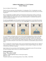
Daisy-Chaining Multiple SRM Loudspeakers
SIG/OLSIG/OLSIG/OLSIG/OLSIG/OLSIG/OLSIG/OLSIG/OL
DL806 Mixer
To next SRM
loudspeaker
input
To next SRM
loudspeaker
input
Main
Outs
Hookup Diagrams continued...
SRM loudspeakers may be daisy-chained via the male XLR connector labeled “THRU”. Simply plug the
signal source (i.e., mixer output) into the input jack(s), and patch that loudspeaker’s THRU jack to the
next loudspeaker’s input jack, and so on, daisy-chaining multiple SRM loudspeakers. Make sure that
the Ch 1 / Mix button is OUT [Ch 1]. See above for a visual representation of daisy-chaining.

Owner’s Manual
9
Owner’s Manual
SRM Loudspeaker: Rear Panel Features
1. Power Connection
Thisisastandard3-prongIECpowerconnector.
Connectthedetachablepowercord(includedin
thepackagingwiththeloudspeaker)tothepower
receptacle,andplugtheotherendofthepower
cordintoanACoutlet.
MakesurethattheACpowerismatchedto
theACpowerindicatedontherearpanel
(belowtheIECreceptacle).
Disconnectingtheplug’sgroundpinis
dangerous.Don’tdoit!
2. Power Switch
Pressthetopofthisrockerswitchinwardstoturn
ontheloudspeaker.ThefrontpanelRunningMan
logowillglowwithhappiness...oratleastitwill
iftheloudspeakerispluggedintoasuitablelive
ACmainssupplyandthemainlogoswitch[10]
isdisengaged.
Pressthebottomofthisrockerswitchinwardstoturn
offtheloudspeaker.
Asageneralguide,SRMloudspeakersshould
beturnedonlast,afteranymixerorother
signalsource.Assuch,theyshouldalsobe
turnedoffrst.Thiswillreducethepossibilityofany
turn-onorturn-offthumpsandothernoisesgenerated
byanyupstreamequipmentfromcomingoutofthe
speakers.
3. XLR and 1/4" Combo Inputs
Bothchannelsfeature1/4"Wide-Z
™
inputswith
combojacksthatmayacceptbalanced/unbalancedXLR
and1/4"connections.ThegainrangeoftheWide-Z
inputsmayhandleanythingfromaninstrumentlevelto
ahigh-outputmicsignal.SimplyconnectanXLR,TRS
orTSconnectorintothechannelandadjustthegain
accordingly.
Pleasebeawareofthepositionofthegain
knob[4].
NEVERconnecttheoutputofanamplier
directlytotheinputoftheloudspeaker.
Thiscoulddamagetheinputcircuitry
oftheactiveloudspeaker.
Theyarewiredasfollows,accordingtostandards
speciedbytheAES(AudioEngineeringSociety):
Balanced XLR Input Connector
Pin1–Shield(ground)
Pin2–Positive(+orhot)
Pin3–Negative(–orcold)
2
3
1
SHIELD
COLD
HOT
SHIELD
COLD
HOT
3
2
1
Balanced XLR Input Connector
SIG/OLSIG/OL
POWER CONSUMPTION 200W
1
2
3 5 6
74
8 9 10
11

SRM550 • SRM650 • SRM750 Powered Loudspeakers
10
SRM550 • SRM650 • SRM750 Powered Loudspeakers
SRM Loudspeaker: Rear Panel Features continued...
Toconnectbalancedlinestotheseinputs,usea
1/4"Tip-Ring-Sleeve(TRS)plug.“TRS”standsfor
Tip-Ring-Sleeve,thethreeconnectionpoints
availableonastereo1/4"orbalancedphonejack
orplug.TRSjacksandplugsareusedforbalanced
signalsandstereoheadphonesandarewiredasfollows
accordingtostandardsspeciedbytheAES(Audio
EngineeringSociety):
Balanced 1/4" TRS Connector
Sleeve–Shield(ground)
Tip–Positive(+orhot)
Ring–Negative(–orcold)
Toconnectunbalancedlinestotheseinputs,usea
1/4"mono(TS)phoneplug,wiredasfollowsaccording
tostandardsspeciedbytheAES(AudioEngineering
Society):
Unbalanced 1/4" TS Connector
Sleeve–Shield(ground)
Tip–Positive(+orhot)
Formoreinformationontheseconnectors,see
AppendixBonpage20.
4. Gain Knobs
Thegainknobsadjusttheinputsensitivityofthe
micandmic/line/RCAinputs.Thisallowssignalsfrom
theoutsideworldtobeadjustedtorunthrougheach
channelatoptimalinternaloperatinglevels.
Thereis–
dBofgainwiththeknobfullydown
(off),rampingupto50dBofgainfullyup(max).
TheaccompanyingLEDwillilluminategreenwhen
thechannel’sinputsignalispresent,indicatingsignal.
Itwillremainlitsolongasthereissignalabove
–20dBupresentinthatchannel.
SLEEVE
TIP
SLEEVE
TIP
RING
RING
TIP
SLEEVERING
Balanced 1/4" TRS Connector
SLEEVE
TIP
TIP
SLEEVE
TIP
SLEEVE
Unbalanced 1/4" TS Connector
TheaccompanyingLEDwillilluminateredwhenthe
amplierintheSRMloudspeakerisneartheclipping
point.ItisokayifthisLEDblinksoccasionally,because
thismeansthatthetransientpeaksarejustreaching
themaximumoutputoftheampliersandyouare
gettingthemostoutofyourloudspeaker.
Ifconnectingmixeroutputstoloudspeaker
inputs,setthegainknobto10:00[“Line”]
foroptimalsoundandperformance.
5. RCA Inputs [Channel 2 Only]
ThestereounbalancedRCAinputsallowyouto
playaCDplayer,iPod
®
,orotherline-levelsource.
TheRCAjacksacceptanunbalancedsignalusing
standardhi-[RCA]hookupcables.
NEVERconnecttheoutputofanamplier
directlytotheinputoftheloudspeaker.
Thiscoulddamagetheinputcircuitry
oftheactiveloudspeaker.
Theyarewiredasfollows,accordingtostandards
speciedbytheAES(AudioEngineeringSociety):
Unbalanced RCA Connector
Sleeve–Shield(ground)
Tip–Positive(+orhot)
Formoreinformationontheseconnectors,see
AppendixBonpage20.
TIPSLEEVETIPSLEEVE
Unbalanced RCA Connector
SIG/OLSIG/OL
3 5 6
74
8 9 10

Owner’s Manual
11
Owner’s Manual
SRM Loudspeaker: Rear Panel Features continued...
6. Thru Output
ThisisamaleXLR-typeconnectorthatproduces
exactlythesamesignalthatisconnectedtothe
maininputjackoramixofchannels1and2.Useitto
daisy-chainseveralSRMloudspeakerstogetheroff
thesamesignalsource(s).
Theyarewiredasfollows,accordingtostandards
speciedbytheAES(AudioEngineeringSociety):
Balanced XLR Output Connector
Pin1–Shield(ground)
Pin2–Positive(+orhot)
Pin3–Negative(–orcold)
Seepage8tolearnmoreaboutdaisy-chainingSRM
loudspeakers.
Formoreinformationontheseconnectors,see
AppendixBonpage20.
7. Ch 1/Mix Switch [Thru Output]
Thisswitchallowsyoutochoosewhetheronly
thechannel1signal(pre-gain)issentouttothe
nextloudspeaker[switchout–Ch1]orifamix
ofthechannel1and2signalsaresentouttothe
nextloudspeaker[switchin–Mix](post-gains).
8. Speaker Mode
Hereyouareabletochangetheloudspeaker’s
speakermodetotailorittobestsuityourparticular
application.Therearefourmodesavailable:PA,DJ,
MonitorandSoloistwitheachSRM550andSRM650
andPA,DJ,FillandSpeechwitheachSRM750.
Pressthespeakermodebuttonrepeatedlyuntilthe
LEDofthespeakermodeyoudesireisilluminated.
RefertotheFrequencyResponsegraphsonpages
23–25forfurtherinformation.
PA Speaker Mode–Thismodeisfullrange,but
focusesonmid-rangeclaritywherevocalsoftenreside.
Thisistheplacetostartformostsoundreinforcement
applications.
DJ Speaker Mode–Thismodebumpsthelowsand
highswithamildtucktothemids,perfectformusic
playback.
2
1
SHIELD
COLD
HOT
3
SHIELD
COLD
HOT
3
2
1
Balanced XLR Output Connector
MON(itor) Speaker Mode–Thismodefeaturesa
lowfrequencyroll-offandareductionaround2kHzto
ensuremaximumgainbeforefeedbackinmonitor
applications.
SOLO(ist) Speaker Mode–Thismodefeatures
alowfrequencyroll-offtogetridofunwantedthumps
andaddsboostandsparkletomid-rangeandhigh
frequencies.Thisplug-and-playmodeisperfectfor
singer-songwriters.
FILL Speaker Mode–Thismodefeaturesamild
lowfrequencyroll-offtoensureminimalonstagelow
frequencybuild-upwhileprovidingarichfullrange
responsewithplentyofmid-highcutthrough.This
plug-and-playmodeisperfectforonstagemonitorside
llapplications,aswellaswhenfacingaudienceareas
whereamainFOHrigwithsubwoofersispresent.
SPEECH Speaker Mode–Thismodefeaturesa
signicantlowfrequencyroll-offtogetridofunwanted
thumps.Italsoaddsboostandsparkletomid-rangeand
highfrequencies,criticalforspeechapplications.This
plug-and-playmodeisperfectforlargervenueapplica-
tionswherespeechistheprimaryaudiosourceinneed
ofclearandpreciseintelligibility.
9. Feedback desTROYer:
Themulti-bandfeedbackdestroyerhuntsdown
offendingfeedbackfrequenciesandappliesuptofour
notchltersautomaticallytodestroyfeedbackand
maximizegainpriortofeedback.Thisisagreattool
forperformerswithoutadedicatedengineer.
TheintegratedandamazinglyaccurateFeedback
Destroyerinstantlyemploysuptofourincredibly
narrow1/16thoctavelterstolocateanderadicate
feedbacksoyouknowyoucanperformfearlessly.
Plus,theentiresystemisprotectedbyourSmart
Protect
™
DSPwhichkicksintoprotectyour
investmentwhenthingsgetpushedalittletoohard.
SIG/OLSIG/OL
8 9 10

SRM550 • SRM650 • SRM750 Powered Loudspeakers
12
SRM550 • SRM650 • SRM750 Powered Loudspeakers
10. Main Logo Switch / Limit LED
TheRunningManlogoonthefrontoftheSRM
loudspeakerilluminateswhenthisswitchisdisengaged
andACpowerisavailableatthemainsinput[1].
EngagetheswitchifyoudonotwanttheRunning
Manlogotoilluminate.
SRMloudspeakershaveabuilt-inlimiterthat
helpstopreventtheamplieroutputsfromclipping
oroverdrivingthetransducers.Thelimitindicator
illuminatesyellowwhenthelimiterisactivated.
It’sokayforittoblinkyellowoccasionally,butif
itblinksfrequentlyorlightscontinuously,turndown
thegainknob[4]untilitonlyblinksoccasionally.
Excessivelimitingmayleadto
overheating,whichinturntripsthe
thermalprotectcircuitryandinterrupts
theperformance.See‘ThermalProtection’on
page13formoreinformation.
11. Extra Knobs, Buttons and LEDs
What’scoolerthanextrabellsandwhistleson
anewtoy?Well,alotofthings,Isuppose,butthat
didn’tstopus!TherearpanelofeachSRMloudspeaker
isstackedwithavarietyofextraknobs,buttonsand
LEDs.Thefollowingisalistofjustsomeofthefeatures
andfunctionsofeach(inalphabeticalorder):
Beer Tap–Whatgoodisaliveshowwithoutapintor
two...ormore?Simplypushandholdinthemomentary
switchuntilyourpintglassislled.
Liquor Tap–Noteveryoneisabeerdrinker.That’s
whyweinstalledthehandy-dandyliquortap,aswell.
Modem–Areyouoldenoughtorememberthesound
ofamodem?Pressthisswitchoncetohavethatsound
pouroutthespeakers.Pressthisswitchtwiceifyou
wouldratherhearthejoyfulsoundsofadot-matrix
printerinstead.
My Favorite Band–Pressthemyfavoriteband
buttonrepeatedlyuntilyourfavoritebandisdisplayed
onthesilkscreen.Whateversong(s)youplaythrough
theseloudspeakerswillsoundlikethebandyou
selected!
Sports–Musicandsportsdemandtwocompletely
differentsetsofsounds.IfusedasasportsPA,setthe
switchtosports.
SRM Loudspeaker: Rear Panel Features continued...
Stadium–Iftheaudienceconsistsofthebartender,
waitstaffandsignicantothers,engagethisswitch.
Inbetweensongsitwillsoundlikeastadiumlled
withadoringfansnearandwide,notcrickets.
Evenwithallthat,we’restilltryingtogureout
whatelseourcrazyengineerspackedintothesethings!
Themanualwillberevisedoncewe’vediscovered
whattheotherknobs,buttonsandLEDsdo.
Untilthen,appreciatethejoyofnewdiscoveries!
12. Rock ‘n Roll
Congratulations,youhavereachedtheend
ofthefeaturessection!Atthispoint,youshould
haveaprettygoodunderstandingofhowtheSRM
loudspeakersfunction.Ifthisistrue,thenextstepis
torock‘nroll!Ifthisisnottrue,headbacktopage9
andreaditalloveragain.Thefollowingpages
discussSRMloudspeakerplacement,roomacoustics,
anin-depthlookatriggingandSmartProtect,technical
informationandmore.Checkitout!
11

Owner’s Manual
13
Owner’s Manual
Smart Protect
ThereareadvancedDSPprotectionmechanisms
designedtosafeguardtheloudspeakersandampliers
frominadvertentdamage.
Theprotectioncircuitsaredesignedto
protecttheloudspeakersunderreasonable
andsensibleconditions.Shouldyouchoose
toignorethewarningsigns[e.g.excessivedistortion],
youcanstilldamagethespeakerbyoverdrivingitpast
thepointofamplierclipping.Suchdamageisbeyond
thescopeofthewarranty.
Limiting
Thedriverhasitsowncompressioncircuitwhich
helpsprotectitfromdamagingtransientpeaks.
Thecompressorisdesignedtobetransparentand
isnotnoticeableundernormaloperatingconditions.
Overexcursion Protection
TheSRM550andSRM650usean18dB/octavehigh-
passlter,whiletheSRM750usesan24dB/octaveBut-
terworthhigh-passlterjustpriortothelow-frequency
amplier.Thispreventsverylowfrequenciesfrombeing
amplied.Excessivelow-frequencyenergycandamage
thewooferbycausingitto“bottomout,”alsoknowas
overexcursion,whichisequivalenttoamechanicalform
ofclipping.
Thermal Protection
Allampliersproduceheat.SRMloudspeakersare
designedtobeefcientbothelectricallyandthermally.
Intheunlikelyeventoftheamplieroverheating,
abuilt-inthermalswitchwillactivate,mutingthe
signal.
Whentheamplierhascooleddowntoasafe
operatingtemperature,thethermalswitchresetsitself,
andtheSRMloudspeakerresumesnormaloperation.
Ifthethermalswitchactivates,tryturningdownthe
levelcontrolanotchortwoonthemixingconsole(or
thebackoftheloudspeaker)toavoidoverheatingthe
amplier.Beawarethatdirectsunlightand/orhotstage
lightsmaybetheculpritofanamplieroverheating.
AC Power
BesuretheSRMloudspeakerispluggedintoan
outletthatisabletosupplythecorrectvoltagespecied
foryourmodel.Itwillcontinuetooperateatlower
voltages,butwillnotreachfullpower.
Besuretheelectricalservicecansupplyenough
amperageforallthecomponentsconnectedtoit.
Werecommendthatastiff(robust)supplyofAC
powerbeusedbecausetheampliersplacehigh
currentdemandsontheACline.Themorepowerthatis
availableontheline,thelouderthespeakerswillplay
andthemorepeakoutputpowerwillbeavailablefora
cleaner,punchierbass.Asuspectedproblemof“poor
bassperformance”isoftencausedbyaweakACsupply
totheampliers.
Neverremovethegroundpinonthepower
cordoranyothercomponentoftheSRM
loudspeaker.Thisisverydangerous.
Care and Maintenance
Theseloudspeakerswillprovidemanyyears
ofreliableserviceifyoufollowtheseguidelines:
• Avoidexposingtheloudspeakerstomoisture.
Iftheyaresetupoutdoors,besuretheyare
undercoverifrainisexpected.
• Avoidexposuretoextremecold(below
freezingtemperatures).Ifyoumustoperate
theloudspeakersinacoldenvironment,warm
upthevoicecoilsslowlybysendingalow-level
signalthroughthemforabout15minutesprior
tohigh-poweroperation.
• Useadryclothtocleanthecabinets.Onlydo
thiswhenthepoweristurnedoff.Avoidgetting
moistureintoanyoftheopeningsofthe
cabinet,particularlywherethedriversare
located.

SRM550 • SRM650 • SRM750 Powered Loudspeakers
14
SRM550 • SRM650 • SRM750 Powered Loudspeakers
Placement
WARNING:Installationshouldonlybedone
byanexperiencedtechnician.Improper
installationmayresultindamagetothe
equipment,injuryordeath.Makesurethatthe
loudspeakerisinstalledinastableandsecureway
inordertoavoidanyconditionsthatmaybedangerous
forpersonsorstructures.
Theseloudspeakersaredesignedtositonthe
oororstageasthemainPA,monitors[SRM550/
SRM650],orllspeakers[SRM750].Checktomake
surethatthesupportsurface(e.g.oor,etc.)hasthe
necessarymechanicalcharacteristicstosupportthe
weightoftheloudspeaker(s).
Theymayalsobepole-mountedviathebuilt-in
socketonthebottomofthecabinet.Besurethepole
iscapableofsupportingtheweightoftheloudspeaker.
Whenpole-mountingloudspeakers,besurethatthey
arestabilizedandsecuredfromfallingoverorbeing
accidentallypushedover.
TheSPM200isagreatoptionwhenusingan
SRMsubwoofer,asitallowsforgreaterextension
thanmostotherpolesavailablenorthoftheSouthPole.
PleasenotethatSRM750loudspeakers
shouldnotbepole-mountedviaSPM200.
Instead,itshouldbestackedontopofthe
subwoofer.Itishighlysuggestedthatstrapsareutilized.
Toreiterate,failuretofollowtheseprecautionsmay
resultindamagetotheequipment,personalinjury,
ordeath.
Theseloudspeakersmayalsobeownviaitsy
pointsasdetailedonpages16–17.Besuretoreadthe
PA-A2EyeboltInstallationInstructions,aswell.
TheseloudspeakersareNOTdesignedtoarray
horizontally.Ifyoufeelyoumustputtwospeakers
side-by-side,youshouldhaveagoodunderstanding
oftherelationshipbetweenthesplayangle(theangle
betweenthefacingsidesofthecabinets)andfrequency
cancellationeffectsbetweencabinets.
Whentwocabinetsarepositionedside-by-side
suchthattherear-angledfacesoftheenclosures
areparallel,thesplayanglewillbe90º.Thismatches
the90˚horizontalcoveragepatternofeachindividual
loudspeaker;theinterferencebetweenthetwocabinets
willbeminimized,butthetotalcoverageof180˚may
betoowideforsomeapplications.Themidandhigh
frequenciesmayalsobereducedforthoseinthecenter
whoaretooclosetotheloudspeakers.
Reducingthesplayanglewillreducethetotal
horizontalcoverage,butitalsocreatesanareaboth
speakersarecovering.Insteadofaneareldhole,
thiswillcausecomb-lteringeffectsinthefrequency
responseintheoverlappingarea.Thesmallerthesplay
angle,themoreenergywillbedeliveredon-axis,butthe
comb-lteringeffectswillgetworseatthesametime.
Toreiterate,though,westronglysuggest
NOTarrayingtheseloudspeakershorizontally.
Experimentationandexperiencewillhelpyound
therighttrade-offforyourapplication.

Owner’s Manual
15
Owner’s Manual
Room Acoustics
SRMloudspeakersaredesignedtosoundfantastic
innearlyeveryapplication.
But,roomacousticsplayacrucialroleintheoverall
performanceofasoundsystem.Herearesome
additionalplacementtipstohelpovercomesome
typicalroomproblemsthatmightarise:
• Placingloudspeakersinthecornersofaroom
increasesthelowfrequencyoutputandcan
causethesoundtobemuddyandindistinct.
• Placingloudspeakersagainstawallincreases
thelowfrequencyoutput,thoughnotasmuch
ascornerplacement.However,thisisagood
waytoreinforcethelowfrequencies,ifso
desired.
• Avoidplacingthespeakersdirectlyona
hollowstageoor.Ahollowstagecanresonate
atcertainfrequencies,causingpeaksanddips
inthefrequencyresponseoftheroom.Itis
bettertoplacethemonasturdystanddesigned
tohandletheweightoftheloudspeaker.
• Positiontheloudspeakerssothehigh-
frequencydriversaretwotofourfeetabove
earlevelfortheaudience(makingallowances
foranaudiencethatmaybestanding/dancing
intheaisles).Highfrequenciesarehighly
directionalandtendtobeabsorbedmuch
easierthanlowerfrequencies.Byproviding
directline-of-sightfromtheloudspeakers
totheaudience,youincreasetheoverall
brightnessandintelligibilityofthesound
system.
• Highlyreverberantrooms,likemany
gymnasiumsandauditoriums,area
nightmareforsoundsystemintelligibility.
Multiplereectionsoffthehardwalls,ceiling,
andoorplayhavocwiththesound.Depending
onthesituation,youmaybeabletotakesome
stepstominimizethereections,suchas
puttingcarpetingontheoors,closing
draperiestocoverlargeglasswindows,or
hangingtapestriesorothermaterialsonthe
wallstoabsorbsomeofthesound.
However,inmostcases,theseremediesarenot
possibleorpractical.Sowhatdoyoudo?
Makingthesoundsystemloudergenerally
doesn’tworkbecausethereectionsbecome
louder,too.Thebestapproachistoprovideas
muchdirectsoundcoveragetotheaudience
aspossible.Thefartherawayyouarefrom
thespeaker,themoreprominentwillbethe
reectedsound.
Usemorespeakersstrategicallyplacedsothey
areclosertothebackoftheaudience.Ifthe
distancebetweenthefrontandbackspeakers
ismorethanabout100feet,youshouldusea
delayprocessortotime-alignthesound.(Since
soundtravelsabout1footpermillisecond,it
takesabout1/10ofasecondtotravel100feet.)
Keepinmindthatthespeakermodeandfeedback
destroyeraretwogreatwaystocompensateforsomeof
theseissues.Seepage11formoreinformation[8,9].

SRM550 • SRM650 • SRM750 Powered Loudspeakers
16
SRM550 • SRM650 • SRM750 Powered Loudspeakers
Rigging
SRMloudspeakersmaybeindividuallyown
usingaPA-A2EyeboltKit,partnumber0028272
[M10x1.5x37mmforgedshouldereyebolts].
WARNING:Installationshouldonlybedone
byanexperiencedtechnician.Improper
installationmayresultindamagetothe
equipment,injuryordeath.Makesurethatthe
loudspeakerisinstalledinastableandsecureway
inordertoavoidanyconditionsthatmaybedangerous
forpersonsorstructures.
WARNING:Thecabinetissuitableforrigging
viaitsypoints.NEVERattempttosuspend
anSRMloudspeakerbyitshandle.
Rigging Design Practices
Riggingaloudspeakerrequiresdetermining:
1.Theriggingmethodsandhardwarethatmeetstatic,
shock,dynamic,andanyotherloadrequirementsfor
supportingtheloudspeakerfromstructure.
2.ThedesignfactorandrequiredWLL(WorkingLoad
Limit)forthissupport.
Westronglyrecommendthefollowingriggingpractices:
1.Documentation:Thoroughlydocumentthedesign
withdetaileddrawingsandpartslists.
2.Analysis:Haveaqualiedprofessional,suchasa
licensedProfessionalEngineer,reviewandapprovethe
designbeforeitsimplementation.
3.Installation:Haveaqualiedprofessionalriggerdo
theinstallationandinspection.
4.Safety:Useadequatesafetyprecautionsand
back-upsystems.
Rigging Hardware and Accessories
Riggingourloudspeakerswillinvariablyrequire
hardwarenotsuppliedbyus.Varioustypesof
load-ratedhardwareareavailablefromavariety
ofthird-partysources.Thereareanumberofsuch
companiesspecializinginmanufacturinghardware
for,designing,andinstallingriggingsystems.Each
oneofthesetasksisadisciplineinitsownright.
Becauseofthehazardousnatureofriggingwork
andthepotentialliability,engagecompaniesthat
specializeinthesedisciplinestodotheworkrequired.
Wedooffercertainaccessoryriggingitemsandsome
ofthemmaybeusedwithavarietyofproducts.While
theseaccessoriesareintendedtofacilitateinstallation,
thewidevarietyofpossibleinstallationconditionsand
arraycongurationsdonotpermitustodeterminetheir
suitabilityorloadratingforanyparticularapplication.
Wearenotinthebusinessofprovidingcomplete
riggingsystems,eitherasdesigners,manufacturers,
orinstallers.Itistheresponsibilityoftheinstallerto
provideaproperlyengineered,load-certiedrigging
systemforsupportingtheloudspeakerfromstructure.
Rigging Notes
TheSRMloudspeaker’sintegralmountingpoints
aredesignedtosupportonlytheweightoftheirown
loudspeakerwithsuitable,externalhardware.This
meansthateachSRMloudspeakermustbesupported
independentlyofanyotherSRMloudspeakerandany
otherloads.Atleastthreeriggingpointsmustbeused
tohanganSRMloudspeaker.
3 Fly Points [SRM550 / SRM650]
MP=MountingPoint
MP MP
MP
Top Rear

Owner’s Manual
17
Owner’s Manual
10 Fly Points [SRM750]
Important Rigging Reminder:
Toreiterate,wearenotinthebusinessofproviding
completeriggingsystems,eitherasdesigners,
manufacturers,orinstallers.Itistheresponsibility
oftheinstallertoprovideaproperlyengineered,
load-certiedriggingsystemforsupportingthe
loudspeakerfromstructure.
TopFly
Points
RearFlyPoint
(adjustsangle)
*SRM750only
MP=MountingPoint
MP
MP
MP
MP
MP
MP
MP
MP
Left and RightBottom
Top
Rear

SRM550 • SRM650 • SRM750 Powered Loudspeakers
18
SRM550 • SRM650 • SRM750 Powered Loudspeakers
Appendix A: Service Information
Poor bass performance
• Checkthepolarityoftheconnectionsbetweenthe
mixerandtheloudspeakers.Youmayhaveyour
positiveandnegativeconnectionsreversedatone
endofonecable,causingoneloudspeakertobe
out-of-phasewiththeother.
• Poorbassperformancemaybetheresultofbad
ACpower.Seethesectiontitled‘ACPower’on
page13forfurtherdetails.
Poor sound
• Isitloudanddistorted?Makesurethatyou’renot
overdrivingastageinthesignalchain.Verifythat
alllevelcontrolsaresetproperly.
• Istheinputconnectorpluggedcompletelyinto
thejack?Besureallconnectionsaresecure.
Noise
• Whatisthepositionofthegainknob?Itshould
beat(ornear)“mic”whenamicisconnected
andat(ornear)“line”whenaline-levelsignal
isconnected.Itshouldbe“off”forallunused
inputs.
• Makesureallconnectionstotheactive
loudspeakersaregoodandsound.
• Makesurenoneofthesignalcablesarerouted
nearACcables,powertransformers,orother
EMI-inducingdevices.
• IstherealightdimmerorotherSCR-baseddevice
onthesameACcircuitastheSRMloudspeaker?
UseanAClinelterorplugtheloudspeakerinto
adifferentACcircuit.
IfyouthinktheSRMloudspeakerhasaproblem,
pleasecheckoutthefollowingtroubleshootingtipsand
doyourbesttoconrmtheproblem.VisittheSupport
sectionofourwebsite(www.720trees.com)whereyou
willndlotsofusefulinformationsuchasFAQsand
otherdocumentation.Youmayndtheanswertothe
problemwithouthavingtopartwithyourloudspeaker.
Troubleshooting
No power
• Ourfavoritequestion:Isitpluggedin?Makesure
theACoutletislive[checkwithatesterorlamp].
• Ournextfavoritequestion:Isthepowerswitch
on?Ifnot,tryturningiton.
• IstheRunningManlogoonthefrontpanel
illuminated?Ifnot,makesuretheACoutlet
islive.Ifso,referto“Nosound”below.
• TheinternalAClinefusemaybeblown.Thisis
notauserserviceablepart.Ifyoususpectthe
AClinefuseisblown,pleaseseethe"Repair"
sectionnext.
No sound
• Istheinputgainknobfortheinputsource
turnedallthewaydown?Verifythatallthegain
knobsinthesystemareproperlyadjusted.Look
atthelevelmetertoensurethatthemixeris
receivingasignal.
• Isthesignalsourceworking?Makesurethe
connectingcablesareingoodrepairandsecurely
connectedatbothends.Makesuretheoutput
levelcontrolonthemixingconsoleisturnedup
sufcientlytodrivetheinputsofthespeaker.
• Makesurethemixerdoesnothaveamuteonora
processorloopengaged.Ifyoundsomethinglike
this,makesurethelevelisturneddownbefore
disengagingtheoffendingswitch.
• Hasitshutdown?Makesurethereisatleast
sixinchesoffreespacebehindeachSRM
loudspeaker.

Owner’s Manual
19
Owner’s Manual
Hum
• Trydisconnectingthecableconnectedtothemain
inputjack.Ifthenoisedisappears,itcouldbe
a“groundloop,”ratherthanaproblemwiththe
SRMloudspeaker.Trysomeofthefollowing
troubleshootingideas:
• Usebalancedconnectionsthroughoutyoursystem
forthebestnoiserejection.
• Wheneverpossible,plugalltheaudioequipment’s
linecordsintooutletswhichshareacommon
ground.Thedistancebetweentheoutletsandthe
commongroundshouldbeasshortaspossible.
Repair
Forwarrantyservice,refertothewarranty
informationonpage27.
Non-warrantyserviceisavailableatafactory-
authorizedservicecenter.Tolocatethenearest
servicecenter,visitwww.720trees.com,click“Contact
TechSupport”andselect“LocateaServiceCenter
orDistributor”[3].ServiceforSRMloudspeakersliving
outsidetheUnitedStatescanbeobtainedthroughlocal
dealersordistributors.
Ifyoudonothaveaccesstoourwebsite,youmaycall
theTechSupportdepartmentat1-800-898-3211,
Monday-Friday,duringnormalbusinesshours,Pacic
Time,toexplaintheproblem.TechSupportwilltellyou
wherethenearestfactory-authorizedservicecenteris
locatedinyourarea.

SRM550 • SRM650 • SRM750 Powered Loudspeakers
20
SRM550 • SRM650 • SRM750 Powered Loudspeakers
Balanced XLR Input Connector
EachSRMloudspeakerhastwofemaleXLR/TRS/TS
comboinputs.Besurethecablesarewiredper
AES(AudioEngineeringSociety)standards:
Balanced XLR Input Connector
Pin1–Shield(Ground)
Pin2–Positive(+orhot)
Pin3–Negative(–orcold)
Balanced XLR Output Connector
ThereisalsoamaleXLRoutputoneachSRM
loudspeakerlabeled“THRU”.Besurethecablesare
wiredperAES(AudioEngineeringSociety)standards:
Balanced XLR Output Connector
Pin1–Shield(Ground)
Pin2–Positive(+orhot)
Pin3–Negative(–orcold)
SRMloudspeakersmaybedaisy-chainedviathemale
XLRconnectorlabeled“THRU”.Simplyplugthesignal
source(i.e.,mixeroutput)intotheinputjack(s),
andpatchthatloudspeaker’sTHRUjacktothenext
loudspeaker’sinputjack,andsoon,daisy-chaining
multipleSRMloudspeakers.Seepage8foravisual
representationofdaisy-chaining.
Balanced XLR Input Connector
2
3
1
SHIELD
COLD
HOT
SHIELD
COLD
HOT
3
2
1
Balanced XLR Output Connector
2
1
SHIELD
COLD
HOT
3
SHIELD
COLD
HOT
3
2
1
Balanced 1/4" TRS Connector
TRSstandsforTip-Ring-Sleeve,thethreeconnections
availableonastereo1/4"cable.Thisallowsfora
directconnectiontothechannel1and2inputjacks
onSRMloudspeakers.Besurethecablesarewiredper
AES(AudioEngineeringSociety)standards:
Balanced 1/4" TRS Connector
Sleeve–Shield(Ground)
Tip–Positive(+orhot)
Ring–Negative(–orcold)
Unbalanced 1/4" TS Connector
TSstandsforTip-Sleeve,thetwoconnections
availableonamono1/4"cable.Thisallowsfora
directconnectiontothechannel1and2input
jacksonSRMloudspeakers.Besurethecablesare
wiredperAES(AudioEngineeringSociety)standards:
Unbalanced 1/4" TS Connector
Sleeve–Shield(Ground)
Tip–Positive(+orhot)
Unbalanced RCA Connector
RCA-typeplugs(alsoknownasphonoplugs)
andjacksareoftenusedinhomestereoandvideo
equipmentandinmanyotherapplications.RCAplugs
areunbalanced.Connectthesignaltothecenterpost
andtheground(earth)orshieldtothesurrounding
“basket.”BesurethecablesarewiredperAES(Audio
EngineeringSociety)standards:
Unbalanced RCA Connector
Sleeve–Shield(Ground)
Tip–Positive(+orhot)
SLEEVE
TIP
SLEEVE
TIP
RING
RING
TIP
SLEEVERING
Balanced 1/4" TRS Connector
SLEEVE
TIP
TIP
SLEEVE
TIP
SLEEVE
Unbalanced 1/4" TS Connector
TIPSLEEVETIPSLEEVE
Unbalanced RCA Connector
Appendix B: Connections
/