Page is loading ...

Fixed industrial scanner data book June1999
Intermec Data Capture
1
The MaxiScan 3000 Series
Fixed Industrial Scanner
Data Book
David Downey
Copyright 1999
Intermec STC, Toulouse France
All rights reserved
Intermec recognises that all trade marks are the property of their respective owners

Fixed industrial scanner data book June1999
Intermec Data Capture
2
1.0. Introduction
The MaxiScan 3000 series scanners are industrial fixed scanners. The scanners are compact and
ruggedised to operate in the following environments:
In
On Performing
This data book is designed to explain the many features and benefits of the scanner and to provide
information to customers on fixed position scanning, options and specifications. Additional information can
be provided by Intermec Technical Product Support.
• Manufacturing Shopfloor
• Receiving and despatch
• Warehousing
• Laboratory
• Integrated
• Conveyor
• Fixed applications
• Processing machines
• Lift-truck mount
• Identification
• Tracking
• Quality control
• Process control
• Sortation
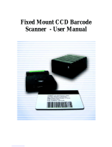
Figure 1. The M000 range of industrial scanners

Fixed industrial scanner data book June1999
Intermec Data Capture
3
2.0 MaxiScan 3000 Series Key Features
Features of the MaxiScan range:
• Range of Scanners for industrial applications
• EasySet software makes them simple to install
• Compact and rugged metal cases (IP65/Nema12)
• High performance optics and decode
• Common connectivity: 15 Pin D type connector with RS 232, 422, 485 and Current
Loop interfaces
• Wide input power range: +7 to 25V unregulated
• Accessories include:
• MCS connection box and power supply
• M3010 RS 485 network concentrator
• Package sensor
• Adjustable stand
Scanner Range:
• MaxiScan 3100SR - linear
• MaxiScan 3100ST - linear
• MaxiScan 3100ML - linear, fixed raster
• MaxiScan 3300ST - linear, raster, multi line
• MaxiScan 3300HR - linear, raster, multi line
•
Maxiscan 3010 network concentrator
The M3100 provides the following key features:
• Cost effective industrial scanning
• Choice of reading distance from 0-10cm (4”) or to 35cm (14”)
• Auto wake up modes (Sensing of codes M3100SR, sensing of item
M3100ST/ML)
• Input and Output synchro signals (voltage or software)
• All main 1D Symbologies and PDF 417
• High ambient light immunity in laser models
The M3300 provides the following key features:
• Very flexible industrial scanning
•
Providing Line, Raster and Multi-direction patterns using Active Line Control (ALC).
•
Reading distance to 65cm (25”)
•
Advanced functions easily configured through EasySet
Simplifies industrial fixed scanning

Fixed industrial scanner data book June1999
Intermec Data Capture
4
3.0 Application Areas
3.1. Conveyor reading
A primary application for the M3xxx is reading products on passing conveyors. The M3100ST and M3300
are designed to be fixed to conveyors and to read codes in ladder or picket orientations (see section 5.3 for
an explanation of these terms). The M3100SR is best suited to ladder orientations. For this application, the
M3000 series is ‘ruggedised’ and sealed so that it can work near heavy machinery and withstand high
levels of dust and moisture. A trigger input allows a signal from a sensor (photo-sensor) on the conveyor to
turn the scanner on so that it is ready to read. When used in this way, the life of the scanner is greatly
extended. The scanners can also send a trigger out on good read or no read that can be used to operate
gates on the conveyor and assist product rejection or sorting.
In this application the scanners may perform identification, tracking or quality control functions and such
applications exist in all forms of automated manufacturing, in logistics and in other processing operations
(laboratory clinical chemistry, etc.).
3.2. Fixed reading
The M3300 can be used as a fixed reader in industrial environments. A typical application is identifying
goods from their shipping labels as they are accepted in a goods receiving area. Here the scanner would be
fixed to a surface or wall allowing packages to be presented or passed in front for reading.
3.3. Truck-mount
The M3300 scanner can be mounted to the front of a fork-lift truck in such a way that it automatically scans
packages picked by the truck. A raster pattern is normally selected to cover the label area and code data is
transmitted to an on-board wireless terminal for sending to the controlling host system. Power would be
supplied by the truck’s VMT (12 or 24V).
3.4. Integrated
In some special applications the M3100 or M3300 are integrated into other machines to provide process
control data. The scanners’compact size, screening and sealing make this application possible. Examples
include photo-processing, medical analysis and packaging machines.

Fixed industrial scanner data book June1999
Intermec Data Capture
5
4.0 MaxiScan 3000 Series key features
4.1. Active Line Control (ALC) – M3300 only
The MaxiScan 3300 is a multi-functional moving-beam bar code laser scanner providing line, raster and
multi-directional scan patterns. The unique scan pattern range stems from Active Line Control (ALC)
technology. ALC gives the user complete control of the scan pattern generation via the configuration
software.
The M3300 can be described as multi-functional because it is equally suited to line, raster and multi-
directional scanning and is capable of working in all main industrial fixed applications: identification,
tracking, process control and sortation on all common 1D symbologies. Most other industrial scanners can
only produce one set pattern (i.e. simple line) and many scanner types are needed to cover a full range of
applications.
The MaxiScan 3300 is easy to install and operate and is supplied with Intermec’s EasySet System (ESS), a
PC Windows based set-up software to support the multi-functional features. ESS simplifies installation
and configuration for both new and advanced users.
The M3300 generates a moving spot by reflecting a laser beam onto two mirrors that are rotated by stepper
motors. By rotating these very small mirrors in different directions and speeds, lines and curves can be
produced.
• Horizontal Scan lines
The basic pattern is a horizontal scan line of
varying lengths for reading picket codes.
• Angled scan lines
Lines at different angles can be produced and
at around 45° can be used to scan picket and
ladder codes by reconstructing the code (from
a fixed length, using check digits etc.).

Fixed industrial scanner data book June1999
Intermec Data Capture
6
• Vertical scan lines
Vertical lines can be generated without
needing to tilt the scanner. These are used for
scanning ladder codes.
• Raster patterns
The horizontal or vertical lines can be swept
through angles of up to 30° to produce raster
patterns. The speed of the raster and length of
lines can be varied. Raster patterns are very
useful for scanning picket codes that may vary
slightly in position as they pass the scanner.
Also raster patterns can read multi-code labels
and the scanner can sort the data before it is
transmitted.
• Multi-direction patterns
The M3300 can produce more complete
patterns to read omni-directional codes.
Different densities of pattern can be produced
depending on the codes to be read. However
it has to be remembered that the more lines
the slower the scan rate on each line.
• Circular patterns
Different size circles can be produced to read
coded ladder codes passing the scanner at
different angles or to read codes randomly
placed around a circular object’s
circumference (such as a tyre wall).
These patterns can be configured using the EasySet setup software supplied. A very useful feature is that a
host system/PLC can send the configuration instructions to the scanner to change its pattern ( to read codes
on different packages on the same conveyor line). It is also possible to set-up a continuously rotating
multi-pattern set with the pattern changing at set time intervals.
Through EasySet, custom patterns can be created to suit particular applications and codes. These patterns
can be tested and tuned on-line to the scanner to ensure the highest reading efficiency.

Fixed industrial scanner data book June1999
Intermec Data Capture
7
Applications often change. ALC allows the scan pattern to be changed to follow the new requirements
without hardware updates. This can result in much lower running costs when compared to conventional
scanners.
ALC simplifies scanner model selection since many applications can be solved by just one scanner model.
This simplifies model selection by the system integrator and the end-user alike. It also reduces the stock
levels from what would be necessary if different scanners had to be supplied for different applications
Key points on ALC :
•
Provides line, angled line, raster and multi-direction patterns
•
Adapts to ladder, picket and omni-directional codes
•
Easy to set-up and customise via EasySet
•
Options include rotating up to 5 patterns continuously or changing patterns under host control
4.2. Optics
The M3100ST and M3300 are equipped with a CPC, a patented light collecting device that improves depth
of field and allows the reading of poor quality and very low contrast codes. These scanners therefore have a
superior reading range and depth of field (see charts in the Appendix) such that the reading distance of the
standard scanner can be compared to other extended range scanners. The CPC allows the scanner to read
label contrasts down to 25% (the CPC is protected by INTERMEC patents).
4.3. Decoding
All decoding is performed by the on-board processor and performed in real-time for single codes. The
M3000 series can recognise and read all common symbologies including: Code 39, 128, EAN 128,
UPC/EAN etc. The M3300 can reconstruct fixed length 39 and 128 codes from partial scans or damaged
labels to ensure high read rates even in the toughest of environments. Also multi-code labels, including
EAN 128, and the stacked code Codablock can be scanned and sorted. A raster pattern would normally be
used to scan these codes.
The M3100 can also read PDF 417.
4.4. Environment
The M3000 series is housed in a tough aluminium case and this is sealed with gaskets to meet the IP65 and
Nema 12 standards. The aluminium is epoxy coated to prevent surface corrosion. This makes the scanner
suitable for most industrial environments including areas where there are dust particles, water droplets and
corrosive chemicals.
The M3300 scanner can operate in a wide temperature range from 0°C to 50°C (32 to 122°F) using an
optional thermo-cooling device to regulate the temperature of the laser diode. The thermo-cooler is a solid
state device that acts as a heat-pump. The laser diode is attached to a metal heat-sink and then to the
thermo-cooler. This in turn is in contact with the outer aluminium case. Heat is thus pumped from the
diode to the case for dissipation. Red laser diodes, as used by most laser scanners, are normally life-
specified at 25°C. When working above 40°C their life is shortened considerably. The thermo-cooler is
designed to keep the diode temperature below this limit even when the ambient temperature is up to 50°C.
Because the internal scanner temperature is above ambient it is recommended that the thermo-cooler be
selected as an option if the scanner’s working ambient temperature is likely to be over 27°C. An
alternative way of controlling the diode’s temperature is to turn the scanner off after each successful scan
and to use an external photo-sensor trigger to wake the scanner up for the next read. Synchronising the
scanner in this way will maximise the working life of the unit (see also section 7.7).

Fixed industrial scanner data book June1999
Intermec Data Capture
8
4.5 EasySet System configuration software
The configuration, testing and tuning of fixed scanners is simplified by Intermec’s EasySet, a Windows
based PC configuration software. EasySet is a unique tool that allows you to work off- or on-line.
In the off-line mode a page is constructed with the configuration codes that specify the desired
configuration. This page is printed and used to perform a quick set-up of one or multiple scanners by
reading the codes. The embedded concatenation feature (patent pending) allows even complicated
configurations to be printed as one bar code. This page can be used to make very fast scanner set-ups in the
field and also to provide a way of confirming the set-up or quickly changing it for a new operation. The
page could be used by an unskilled operator if required.
When using on-line, different configurations can be downloaded instantly via an RS 232 link, tested, and
feedback on efficiency used to aid the selection of the best parameters.
EasySet a revolutionary new way to configure bar code scanners.
See section 6 for a full description of EasySet.

Fixed industrial scanner data book June1999
Intermec Data Capture
9
5.0 Fundamentals of Fixed Position Scanning
5.1 The bar code
The M3000 series is principally designed to read linear symbologies (bar codes). A linear bar code is a
number of bars and spaces containing data arranged in parallel rows. These codes are usually read in 1D
using a scanning line. The scanners can read some stacked codes such as PDF 417 (M3100) and
Codablock (M3300). Stacked codes are essentially a number of linear codes stacked on each other with
some common organisation. Stacked codes are a type of 2D code but they can be read by 1D readers if the
scanning line is swept over the code in such a way that each individual line is read.
123 Codablock
Fig 3. A linear bar code (Code 39) Fig 4. A stacked bar code (Codablock)
For fixed applications it is important to understand the symbology(s) used by the application and also its
print specification. It is often useful to get a sample of the code and make some reading tests before
attempting to install a scanner.
To understand the bar code it is necessary to know the following details:
• The Symbology
1. Which symbology, is it available as standard?
1. If more than one, how many (can influence decoding time if more than two are selected)?
2. Is it a fixed length or is there a check digit that can be used to speed decoding and maximise
security?
• Physical dimensions
1. Length and height. What size is the code? This is important in calculating the number of times it
will be scanned as it passes the scanner in conveyor applications. The height of the bars is
important as, depending on the scanning method, it can provide ‘redundancy’ - damaged areas in
one slice (plane) can be read in another slice above or below the damaged area.
2. What is the X Dimension? The X dimension is the width of the narrowest element and is
expressed in mm or mils (1mil=0.254mm). This dimension can be compared against reading zone
graphs to see what the depth of field will be for a given code.

Fixed industrial scanner data book June1999
Intermec Data Capture
10
3. Quiet Zone. This clear area is required by the specification of most codes. For reliable reading
this zone should be equal to 10 * the X Dimension.
Fig 5. The parts of a code (EAN 13 code)
• Print quality
1. How is the code printed? Thermal transfer or direct thermal give the best quality although
some newer ink-jet printers can give comparable quality. Do the codes range in quality or
contrast? samples of the worst quality expected will help to ensure that the scanner is set-up
to read all codes.
2. What is the print media, a pack or label? What is the stock? Is it matt, glossy or reflective.
Will it degrade with time?
In general it is useful to use a bar code verifier to check the code sample and compare against the scanner
specifications.
5.2 Bar code scanning
The M3xxx scanners illuminate the bar code with a laser beam produced by a visible red laser diode or, in
the case of the M3100SR, an led array. The beam is used to generate a line or pattern to cover the bar code.
Reflected light is filtered and captured by a photo-diode or CCD. The resulting signal is optimised,
analysed and finally decoded to discover the actual data.
The X
dimension
The Quiet Zone
(more than 10X)
The bar height

Fixed industrial scanner data book June1999
Intermec Data Capture
11
5.3 Orientation
Linear bar codes do not have significant error correction and therefore the scanning line must completely
cover the bar code to achieve a successful scan. The size of the code, its Aspect Ratio (ratio of height to
length) and orientation to the scanner are critical if the scanner is to be correctly configured for an
application.
Two orientations of codes are used: Picket and Ladder:
• Picket Codes
Picket codes are more commonly used as they give the reader more time to see the code (as the code passes
along the scan line) and make a number of successful scans. However if a mono line pattern is selected,
only a thin slice of the bar code will be used. This wastes the vertical redundancy in the height of the code
and if there is a printing error in the slice seen by the scanner the code will not be read. Therefore for
picket codes it is preferential to use a slightly tilted line or a raster pattern. Some scanners (M3100ML) use
a set number of parallel lines to cover the code. This is often called a raster but is really a multi-line
pattern. The lines are often usually very close (equal to a raster angle of 5-10°). The M3300 is a true
raster scanner. A sweeping line covers the codes and can be adjusted depending on the bar-height and any
variation in the placement of the label. The whole height of the bars is scanned to ensure maximum read
rates.
Good scan
Maximum
angle
Maximum
angle
Fig 6. Maximum code/scan
line tilt angles

Fixed industrial scanner data book June1999
Intermec Data Capture
12
It is important to know how good the label placement is relative to the scanner. Each scanner has a spec for
reading a label and the following terms are used to describe the position of the label relative to the scan:
Tilt
can severely reduce the number of scans per label by effectively reducing the bar height from the
scanners view. Tilt should be avoided as far as possible. If this is not possible then it may be worth trying a
multi-direction pattern or alternating pattern to ensure that every code intersects a scan line and is read.
Skew
again reduces the bar height when viewed from the scanners position. Varying the pattern will not help
improve skew .
Pitch
occurs when the label is at an angle to the scanner such that one end is further from the scanner than the
other. The effect is the same as reducing the X Dimension to the scanner. The denser the label, the more
important it is to eliminate pitch.
•
Ladder Codes
Ladder codes can perform well with line scanners and patterns as when the code passes the scan line the whole
height of the code is used. However, the time that the code is being read by the line is very short compared to
Fig. 9. A ladder code and scan line
Fig 8 Picket codes - problems and terms

Fixed industrial scanner data book June1999
Intermec Data Capture
13
a picket code and thus the number of scans per code can be very small. This has security problems (see
section 7.4 on number of scans per code).
The position of the label relative to the scanner causes similar effects to picket codes. The Pitch and Skew
definitions have to be understood since they apply to the label but appear to be different according to the
package:
5.3 Conveyor / code speed
The label orientation, scan line length, scan rate, bar height and conveyor speed should all be adjusted so
that the scanner is able to make at least five complete scans (preferably more than 7) as the code passes by.
This will guarantee good read rates.
For picket codes the number of scans can be calculated as follows:
Number of scans = ((Ws-Wc) x Sr/Cs) - 2
Where Ws = Width of scan line
Wc = Width of code
Sr = Scan rate
Cs = Conveyor speed
Note: ensure that the units of measurement used are common.
Example :
For a conveyor moving at 5m/s, a code width of 4cm, a scan line of 20cm and a scan rate of
450 scans/sec the number of scans will be
((20-4) x 450/500)-2 = 12 scans
Fig 10. Ladder codes - problems and terms

Fixed industrial scanner data book June1999
Intermec Data Capture
14
For angled picket codes, the number of scans should be calculated by reducing the width of scan figure
(Ws) in proportion to the tilt angle.
For ladder codes the formula is
Number of scans = (Hc/Cs x Sr) - 2
Where Hc = Height of code
Cs = Conveyor speed
Sr = Scan rate
Example :
For a conveyor moving at 5m/s, a code height of 7cm and a scan rate of 450 the number of
scans will be :
(7/500 x 450) - 2 = 4.3 scans
This demonstrates how with similar parameters, the number of scans for a ladder code will be smaller than
for a picket code. In the above situation the code height would have to be increased or the conveyor speed
slowed for the given scan rate.
It can be useful to calculate the minimum height required for a given scan rate and conveyor speed:
Height of code = Cs x (Ns + 2 )/Sr
Where Cs = Conveyor speed
Ns = Number of scans
Sr = Scan rate

Fixed industrial scanner data book June1999
Intermec Data Capture
15
6.0 INTERMEC’s EasySet System
The M3000 series is supplied with a Windows compatible configuration software package on CD-ROM.
This software makes the configuration easy to do and gives two options for communicating to the scanner:
•
Off-line mode – by printing a custom configuration card
•
On-line mode – by RS 232 link with the scanner
EasySet is in fact common to different Intermec products and when entering the software, the correct
product must be selected. EasySet provides the following features:
6.1 Displays default set-up
The set-up commands are show in a ‘command selector’ window. Set-up commands selected by default
are marked with an asterix.
6.2 Off-line use
The software can be used off-line to make custom set-up pages including the selected commands as bar
codes. This allows a configuration (or several possible configurations) to be made off-site and used on-site
to quickly set-up scanners. The set-up page should be kept on-site as a reference. It also makes it possible
for untrained staff to change the configuration quickly if required.
Command
Selector
Product
Selector
Selected
commands and
set-up codes
Set-up viewer.
Can be printed
as a custom set-
up sheet. See
off-line mode
Command
search box
Send commands to
reader via comms
port
Fig 11. The EasySet System software

Fixed industrial scanner data book June1999
Intermec Data Capture
16
A unique concatenation feature makes it possible for the set-up codes to be merged as one code that
contains all the information to configure the scanner. This feature is especially useful if the sheet is to be
used to set-up many scanners or is to be used by untrained staff.
6.3 On-line Mode
In this mode the software communicates directly with a scanner to send set-up information. An advantage
of this is that each set-up change can be immediately tested to ensure it works and also to see if it helps
reading efficiency.
By printing this page the
codes can be used as a
custom set-up page for
configuring one or many
scanners. The page also
becomes a reference for
future use.
A unique
concatenation feature
allows the set-up
codes to be merged
and printed as one
code. This makes
setting up multiple
scanners very fast.
Fig 12. The page viewer showing set-up
codes
Fig 13. The page viewer with a concatenated
code.

Fixed industrial scanner data book June1999
Intermec Data Capture
17
6 .4 Terminal function
A terminal mode allows the scanner to send data to the PC so that configurations can be tested. The
M3300 has a reading efficiency test allows the scanner to be tuned for maximum read rates.
6.5 M3300 Set-up tips using EasySet
Folder 4 in EasySet :
Select Patterns : Different scan patterns can be selected here. Select a pre-defined pattern or specify a
unique pattern for the application. Ensure that the pattern line will intersect the bar code properly and
account for any movement in the code relative to the scanner. Limit the area scanned to where the bar
code will be and add a 15% tolerance margin. Avoid scanning the area around the bar code (but keep a
15% tolerance zone) as every scan of ‘empty space’ has the same effect as reducing the scan rate.
Multi-Pattern Sequence : A number of different patterns can be selected and a duration set for each one.
This will make the scanner cycle between patterns and can be useful to cover applications where the bar
code placement or orientation varies.
Contrast Levels : This optimises the scanner to the type of label contrast (or distance) and will improve
performance if set correctly. It may be necessary to test different settings to establish the correct setting.
Resolution adjustment : The M3300 default is to switch between two video channels to ensure that all
high and low resolution codes are read. If it is known that all the codes will be high or low resolution
then the parameter should be set accordingly. This could have the same effect of doubling the scan
rate on a some codes !
Data Decoding security : The scanner can be set to read a code a pre-set number of times before
transmission, or to avoid multiple reads of the same code.
Synchronisation : The hardware synch in and out can be set here. The scanner will have to be wired
with the sensor as shown in the installation manual. The software synch out allows the scanner to send a
message on successful or unsuccessful reads. The messages may be composed here.
Filter Masks : This option allows the scanner to be set to read codes with only certain symbologies
and/or data strings. This is used in Multi-Code reading.
Multi-Code Reading : If more than one code is in the scanner’s field of view at any one time then these
parameters allow the number of codes to be read to be specified. Also the code reading and
transmission can be set by symbology or Filter Mask order (see above). The data from all codes can be
concatenated if required.
Reading Count Mode : The number of good reads made by the scanner can be sent as additional data if
required.
Folder 5 in EasySet :
Continuous Configuration Mode : By default, the scanner is set to only read configuration data for one
minute after power on. If required this parameter can be activated so that the scanner can always
receive configuration data by set-up codes or via the RS232 line. This allows the scanner to be
reconfigured at will by the operator or by the host (i.e. Change Scan Pattern). Each new configuration
will be stored in EPROM and this process takes about two seconds. Thus the scanner will be unable to
read for two seconds after the reconfiguration.
Temporary Configuration Mode : This mode allows the scanner to read set-up codes or accept host
commands at any time but they are not stored. The configuration will reset when power is off. Using
this mode enables configuration changes to be made with a time delay of only 0.5 seconds.

Fixed industrial scanner data book June1999
Intermec Data Capture
18
7.0 Optimising an application
9.1. Scan line or pattern
Ensure that the scan line or pattern is best suited to the code.
Hints for picket codes :
If a single line is being used, tilt it slightly to allow it to see more of the bar-code height:
Also increase the scan width (scan angle) to the maximum for the scanner. If possible reduce the length of
the code ensuring that the X dimension is still suitable for the scanner at the range used. Adjusting the
range will also help to optimise this label orientation.
If a raster is being used, set the raster angle to cover only the height of the code (allow for maximum label
position variation). Do not waste scans outside of the code area.
Hints for ladder codes:
Use a vertical linear pattern and adjust the line length to cover only the length of the code (allow for
maximum label position variation). Do not waste scans outside of the code area. If possible increase the
height of the code itself to the maximum for the label or package.
9.2. Specula Reflection
If the label is at 90° exactly to the plane of the laser beam then the label (like a mirror) will reflect too
much light into the scanner and the code will not be read. The code / scanner should be pitched or skewed
slightly to avoid this. When using raster or multi-line patterns ensure that specula reflection is not present
in any part of the scan.
9.3 Density
Depending on the code, the scanner can be tuned for particular densities of codes. By default, the scanner
is set in an interleaved mode for all densities. On dense codes the high resolution mode should be selected
and for low density codes the low resolution mode should be selected through EasySet. This will increase
efficiency rates.
9.4 Contrast
Again through EasySet a number of settings may be changed (effectively a noise level adjustment) to
optimise the scanner for high or low contrast codes.
Fig. 14. A picket code and scan line
angled to ‘see’ more of the code height

Fixed industrial scanner data book June1999
Intermec Data Capture
19
9.5 Efficiency
For the M3300 use the terminal efficiency reading in EasySet to test the scanner, code and label set-ups.
9.6 Input Synchronisation
Wherever possible, an input trigger from a sensor (opto) should be used to turn the scanner on to scan.
This will ensure that the scanner only scans when an object is present. This reduces the temperature inside
the scanner and maximises the scanner’s MTBF.
9.7 Thermo-cooler for M3300
Ensure that if the ambient temperature is above 27°C, the thermo-cooler option is selected and/or use the
scanner with a sensor as described in point 9.6.
The M3300 scanner should operate with a MTBF of 20 000 hours at 25°C. To maintain this performance
at higher ambient temperatures the following is necessary :
•
0 - 27°C standard operation
•
28- 40° use therrmo-cooler option
•
40°- 50° use thermo-cooler and input synchro to reduce duty cycle to <50%
The M3300 is ideally suited to input synchronisation since the moving mass is very small and both the laser
and motors can be turned off and on instantaneously (1ms). This greatly increases the working life of the
scanner in high temperature environments.

Fixed industrial scanner data book June1999
Intermec Data Capture
20
Appendix
A1. Application Checklist
A2. Technical Characteristics &
Drawings
A3. Connections and Cables
A4. Parts List
/