
507052-04 Page 1 of 53Issue 1727
INSTALLATION INSTRUCTIONS
A95DF2V & 95G2DFV
Warm Air Gas Furnace / Downow Air Discharge
Direct Vent & Non-Direct Vent
Save these instructions for future reference
(P) 507052-04
*P507052-04*
Manufactured By
Allied Air Enterprises LLC
A Lennox International, Inc. Company
215 Metropolitan Drive
West Columbia, SC 29170
This manual must be left with the homeowner for future reference.
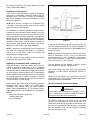
This is a safety alert symbol and should never be ignored. When you see this symbol on labels or in
manuals, be alert to the potential for personal injury or death.
Improper installation, adjustment, alteration, service
or maintenance can cause property damage, personal
injury or loss of life. Installation and service must be
performed by a licensed professional installer (or
equivalent), service agency or the gas supplier.
WARNING
As with any mechanical equipment, personal injury can
result from contact with sharp sheet metal edges. Be
careful when you handle this equipment.
CAUTION
Table of Contents
Unit Dimensions ..........................................................2
Parts Arrangement.......................................................3
Gas Furnace ................................................................4
Shipping and Packing List ...........................................4
Safety Information .......................................................4
General ........................................................................6
Combustion, Dilution & Ventilation Air .........................7
Installation .................................................................10
Filters .........................................................................12
Duct System ..............................................................12
Venting Practices .......................................................15
Condensate Piping ....................................................32
Gas Piping .................................................................35
Electrical ....................................................................37
Testing for Proper Venting and Sufcient Combustion
Air for Non-Direct Vent Applications ..........................44
Unit Start-Up ..............................................................45
Blower Performance ..................................................48
Service.......................................................................50
Planned Service ........................................................52
Repair Parts List ........................................................52

507052-04Page 2 of 53 Issue 1727
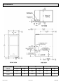
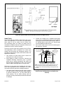
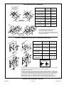
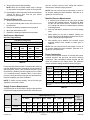
Unit Dimensions
A95DF2V / 95G2DFV
Capacity
A B C
in. mm in. mm in. mm
045-12
070-16
17-1/2 446 16-3/8 416 16 406
090-20
110-20
21 533 19-7/8 504 19-1/2 495

507052-04 Page 3 of 53Issue 1727
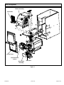
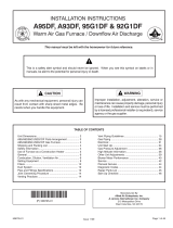
Parts Arrangement
Figure 1.
Access Panel
Combustion Air
Inducer
Burner Box
Assembly
Gas Valve
Control Box
Blower Assembly

507052-04Page 4 of 53 Issue 1727
Gas Furnace
This Category IV gas furnace is shipped ready for
installation in the downow position.
The furnace is equipped for installation in natural gas
applications. A conversion kit (ordered separately) is
required for use in LP/propane gas applications.
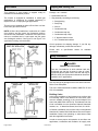
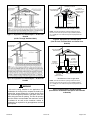
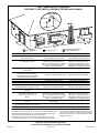
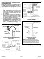
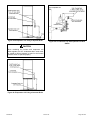
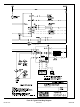
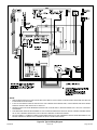
This unit can be installed as either a Direct Vent or a Non-
Direct Vent gas central furnace.
NOTE: In Direct Vent installations, combustion air is taken
from outdoors and ue gases are discharged outdoors.
Non-Direct Vent installations, combustion air is taken from
indoors or ventilated attic or crawl space and ue gases
are discharged outdoors. See Figure 2 and Figure 3 for
application involving roof termination.
Figure 2.
Figure 3.
Shipping and Packing List
Package 1 of 1 contains:
1 - Assembled Gas Unit
1 - Bag assembly containing the following:
1 - Snap bushing
1 - Snap Plug
1 - Wire tie
1 - Condensate trap
1 - Condensate trap cap
1 - Condensate trap clamp
1 - 2” diameter debris screen
1 - 3/4” Threaded street elbow
Check equipment for shipping damage. If you nd any
damage, immediately contact the last carrier.
Please refer to specication sheets for available
accessories.
Safety Information
DANGER OF EXPLOSION!
There are circumstances in which odorant used with
LP/propane gas can lose its scent. In case of a leak,
LP/propane gas will settle close to the oor and may be
difcult to smell. An LP/propane leak detector should be
installed in all LP applications.
DANGER
Use only the type of gas approved for use with this furnace.
Refer to unit nameplate.
This unit is CSA International certied to ANSI Z21.47 and
CSA 2.3 standards.
Building Codes
In the USA, installation of gas furnaces must conform with
local building codes. In the absence of local codes, units
must be installed according to the current National Fuel
Gas Code (ANSI Z223.1/NFPA 54). The National Fuel Gas
Code is available from the American National Standards
Institute, Inc., 11 West 42nd Street, New York, NY 10036.
In Canada, installation must conform with current National
Standard of Canada CSA-B149 Natural Gas and Propane
Installation Codes, local plumbing or waste water codes
and other applicable local codes.
In order to ensure proper unit operation in non-direct vent
applications, combustion and ventilation air supply must

507052-04 Page 5 of 53Issue 1727
be provided according to the current National Fuel Gas
Code or CSA-B149 standard.
Locations and Clearances
This furnace is CSA International certied for installation
clearances to combustible material as listed on the unit
nameplate and in the table in Figure 14. Accessibility
and service clearances must take precedence over re
protection clearances.
NOTE: When furnace is installed on a combustible oor,
a downow combustible ooring base must be installed
between the furnace and the oor.
For installation in a residential garage, the furnace must be
installed so that the burner(s) and the ignition source are
located no less than 18 inches (457 mm) above the oor.
The furnace must be located or protected to avoid physical
damage by vehicles. When a furnace is installed in a public
garage, hangar, or other building that has a hazardous
atmosphere, the furnace must be installed according to
recommended good practice requirements and current
National Fuel Gas Code or CSA B149 standards.
NOTE: Furnace must be adjusted to obtain a temperature
rise within the range specied on the unit nameplate.
Failure to do so may cause erratic limit operation and
premature heat exchanger failure.
This gas furnace must be installed so that its electrical
components are protected from water.
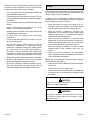
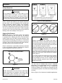
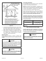
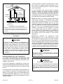
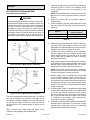
Installed in Combination with a Cooling Coil
When this furnace is used with cooling units (Figure 4),
it shall be installed in parallel with, or on the upstream
side of, cooling units to avoid condensation in the heating
compartment. With a parallel ow arrangement, a damper
(or other means to control the ow of air) must adequately
prevent chilled air from entering the furnace. If the damper
is manually operated, it must be equipped to prevent
operation of either the heating or the cooling unit, unless it
is in the full HEAT or COOL setting.
When installed, this furnace must be electrically grounded
according to local codes. In addition, in the United States,
installation must conform with the current National
Electric Code, ANSI/NFPA No. 70. The National Electric
Code (ANSI/NFPA No. 70) is available from the following
address:
National Fire Protection Association
1 Battery March Park
Quincy, MA 02269
Figure 4.
In Canada, all electrical wiring and grounding for the unit
must be installed according to the current regulations of
the Canadian Electrical Code Part I (CSA Standard C22.1)
and/or local codes.
NOTE: This furnace is designed for a minimum continuous
return air temperature of 60°F (16°C) or an intermittent
operation down to 55°F (13°C) dry bulb for cases where a
night setback thermostat is used. Return air temperature
must not exceed 85°F (29°C) dry bulb.
This gas furnace may be installed in alcoves, closets,
attics, basements, garages, and utility rooms.
This furnace design has NOT been CSA certied for
installation in mobile homes, recreational vehicles, or
outdoors.
Never use an open ame to test for gas leaks. Check all
connections using a commercially available soap solution
made specically for leak detection.
Use of Furnace as Construction Heater
Gas furnaces manufactured on or after May 1, 2017,
are not permitted to be used in Canada for heating of
buildings or structures under construction.
WARNING
The following statement only applies to the US. Allied
Air does not recommend the use of these units as a
construction heater during any phase of construction. Very
low return air temperatures, harmful vapors, construction
dust and operation of the unit with clogged or misplaced
lters may damage the unit.

507052-04Page 6 of 53 Issue 1727
However, these units may be used for heating of buildings
or structures under construction in the US if the following
conditions are met to ensure proper operation:
• The vent system must be permanently installed per
these installation instructions.
• A room thermostat must control the furnace. The use
of xed jumpers that will provide continuous heating is
not allowed.
• The return air duct must be provided and sealed to the
furnace.
• Return air temperature range between 60°F (16°C)
and 80°F (27°C) must be maintained.
• Air lters must be installed in the system and must be
maintained during construction.
• Air lters must be replaced upon construction
completion.
• The input rate and temperature rise must be set per
the furnace rating plate.
• One hundred percent (100%) outdoor air must be
provided for combustion air requirements during
construction. Temporary ducting may supply outdoor
air to the furnace. Do not connect duct directly to
the furnace. Size the temporary duct following the
instructions in section for Combustion, Dilution and
Ventilation Air in a conned space with air from outside.
• The furnace heat exchanger, components, duct system,
air lters and evaporator coils must be thoroughly
cleaned following nal construction cleanup.
• All furnace operating conditions (including ignition,
input rate, temperature rise and venting) must be
veried according to these installation instructions.
General
These instructions are intended as a general guide and do
not supersede local codes in any way. Consult authorities
having jurisdiction before installation.
In addition to the requirements outlined previously, the
following general recommendations must be considered
when installing one of these furnaces:
• Place the furnace as close to the center of the air
distribution system as possible. The furnace should
also be located close to the vent termination point.
• When the furnace is installed in non-direct vent
applications, do not install the furnace where drafts
might blow directly into it. This could cause improper
combustion and unsafe operation.
• When the furnace is installed in a non-direct vent
applications, do not block the furnace combustion air
opening with clothing, boxes, doors, etc. Air is needed
for proper combustion and safe unit operation.
• When the furnace is installed in an attic or other
insulated space, keep insulation away from the
furnace.
• When the furnace is installed in an unconditioned
space, consider provisions required to prevent freezing
of the condensate drain system.
NOTE: The Commonwealth of Massachusetts stipulates
these additional requirements:
• Gas furnaces shall be installed by a licensed plumber
or tter only.
• The gas cock must be “T handle” type.
• When a furnace is installed in an attic, the passageway
to and service area surrounding the equipment shall
be oored.
These units should not be installed in areas normally
subject to freezing temperatures.
CAUTION
This product contains a chemical known to the State
of California to cause cancer, birth defects or other
reproductive harm.
WARNING

507052-04 Page 7 of 53Issue 1727
Combustion, Dilution & Ventilation Air
If this unit is installed as a Non-Direct Vent Furnace, follow
the guidelines in this section.
NOTE: In Non-Direct Vent Installations, combustion air is
taken from indoors and ue gases are discharged outdoors.
Insufcient combustion air can cause headaches,
nausea, dizziness or asphyxiation. It will also cause
excess water in the heat exchanger resulting in rusting
and premature heat exchanger failure. Excessive
exposure to contaminated combustion air will result
in safety and performance related problems. Avoid
exposure to the following substances in the combustion
air supply:
• Permanent wave solutions
• Chlorinated waxes and cleaners
• Chlorine base swimming pool chemicals
• Water softening chemicals
• De-icing salts or chemicals
• Carbon tetrachloride
• Halogen type refrigerants
• Cleaning solvents (such as perchloroethylene)
• Printing inks, paint removers, varnishes, etc.
• Hydrochloric acid
• Cements and glues
• Antistatic fabric softeners for clothes dryers
• Masonry acid washing materials
WARNING
In the past, there was no problem in bringing in sufcient
outdoor air for combustion. Inltration provided all the air
that was needed. In today’s homes, tight construction
practices make it necessary to bring in air from outside
for combustion. Take into account that exhaust fans,
appliance vents, chimneys, and replaces force additional
air that could be used for combustion out of the house.
Unless outside air is brought into the house for combustion,
negative pressure (outside pressure is greater than inside
pressure) will build to the point that a down draft can
occur in the furnace vent pipe or chimney. As a result,
combustion gases enter the living space creating a
potentially dangerous situation.
In the absence of local codes concerning air for combustion
and ventilation, use the guidelines and procedures in this
section to install these furnaces to ensure efcient and safe
operation. You must consider combustion air needs and
requirements for exhaust vents and gas piping. A portion
of this information has been reprinted with permission from
the National Fuel Gas Code (ANSI-Z223.1/NFPA 54). This
reprinted material is not the complete and ofcial position
of ANSI on the referenced subject, which is represented
only by the standard in its entirely.
In Canada, refer to the CSA B149 Installation codes.
Do not install the furnace in a corrosive or contaminated
atmosphere. Meet all combustion and ventilation air
requirements, as well as all local codes.
CAUTION
All gas-red appliances require air for the combustion
process. If sufcient combustion air is not available,
the furnace or other appliance will operate inefciently
and unsafely. Enough air must be provided to meet the
needs of all fuel-burning appliances and appliances such
as exhaust fans which force air out of the house. When
replaces, exhaust fans, or clothes dryers are used at the
same time as the furnace, much more air is required to
ensure proper combustion and to prevent a down draft.
Insufcient air causes incomplete combustion which can
result in carbon monoxide.
In addition to providing combustion air, fresh outdoor air
dilutes contaminants in the indoor air. These contaminants
may include bleaches, adhesives, detergents, solvents
and other contaminants which can corrode furnace
components.
The requirements for providing air for combustion and
ventilation depend largely on whether the furnace is
installed in an unconned or a conned space.
Unconned Space
An unconned space is an area such as a basement
or large equipment room with a volume greater than 50
cubic feet (1.42 m³) per 1,000 Btu (.29 kW) per hour of
the combined input rating of all appliances installed in that
space. This space also includes adjacent rooms which are
not separated by a door. Though an area may appear to
be unconned, it might be necessary to bring in outdoor air
for combustion if the structure does not provide enough air
by inltration. If the furnace is located in a building of tight
construction with weather stripping and caulking around
the windows and doors, follow the procedures in the “Air
from Outside” section.
Conned Space
A conned space is an area with a volume less than 50
cubic feet (1.42 m³) per 1,000 Btu (.29 kW) per hour of
the combined input rating of all appliances installed in that
space. This denition includes furnace closets or small
equipment rooms.
When the furnace is installed so that supply ducts carry
air circulated by the furnace to areas outside the space

507052-04Page 8 of 53 Issue 1727
containing the furnace, the return air must be handled by
ducts which are sealed to the furnace casing and which
terminate outside the space containing the furnace. This
is especially important when the furnace is mounted on
a platform in a conned space such as a closet or small
equipment room. Even a small leak around the base of the
unit at the platform or at the return air duct connection can
cause a potentially dangerous negative pressure condition.
Air for combustion and ventilation can be brought into the
conned space either from inside the building or from
outside.
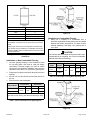
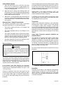
Air from Inside
If the conned space that houses the furnace adjoins a
space categorized as unconned, air can be brought in
by providing two permanent openings between the two
spaces. Each opening must have a minimum free area of 1
square inch (645 mm²) per 1,000 Btu (.29 kW) per hour of
total input rating of all gas-red equipment in the conned
space. Each opening must be at least 100 square inches
(64516 mm²). One opening shall be within 12 inches (305
mm) of the top of the enclosure and one opening within 12
inches (305 mm) of the bottom. See Figure 5.
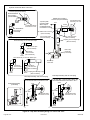
Figure 5. Equipment in Conned Space - All Air from
Inside
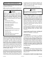
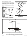
Air from Outside
If air from outside is brought in for combustion and
ventilation, the conned space shall be provided with two
permanent openings. One opening shall be within 12” (305
mm) of the top of the enclosure and one within 12” (305 mm)
of the bottom. These openings must communicate directly
or by ducts with the outdoors or spaces (crawl or attic) that
freely communicate with the outdoors or indirectly through
vertical ducts. Each opening shall have a minimum free
area of 1 square inch per 4,000 Btu (645 mm² per .59 kW)
per hour of the total input rating of all equipment in the
enclosure (see Figure 6 and Figure 7).
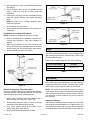
It is also permissible to bring air for combustion from a
ventilated attic (Figure 9) or ventilated crawl space (Figure
10).
Figure 6. Equipment in Conned Space - All Air from
Outside
(Inlet Air from Crawl Space and Outlet Air to
Ventilated Attic)
When communicating with the outdoors through horizontal
ducts, each opening shall have a minimum free area of 1
square inch (645 mm²) per 2,000 Btu (.56 kW) per hour of
the total input rating of all equipment in the enclosure. See
Figure 8.
When ducts are used, they shall be of the same cross-
sectional area as the free area of the openings to which
they connect. The minimum dimension of rectangular
air ducts shall be no less than 3 inches (75 mm). In
calculating free area, the blocking effect of louvers, grilles,
or screens must be considered. If the design and free area
of protective covering is not known for calculating the size
opening required, it may be assumed that wood louvers
will have 20 to 25 percent free area and metal louvers and
grilles will have 60 to 75 percent free area. Louvers and
grilles must be xed in the open position or interlocked
with the equipment so that they are opened automatically
during equipment operation.

507052-04 Page 9 of 53Issue 1727
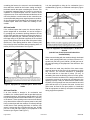
Figure 7. Equipment in Conned Space - All Air from
Outside
(All Air Through Ventilated Attic)
Figure 8. Equipment in Conned Space - All Air from
Outside
If this unit is being installed in an application with
combustion air coming in from a space serviced by an
exhaust fan, power exhaust fan, or other device which
may create a negative pressure in the space, take care
when sizing the inlet air opening. The inlet air opening
must be sized to accommodate the maximum volume
of exhaust air as well as the maximum volume of
combustion air required for all gas appliances serviced
by this space.
WARNING
Ventilation Louvers
Inlet Air
(Minimum 12 in.
(305mm) above
Attic Floor)
Roof Terminated
Exhaust Pipe
Furnace
*Intake Debris
Screen
(Provided)
* See Maximum Vent Lengths table
NOTE: The inlet and outlet air openings shall each have a
free area of at least one square inch per 4,000 Btu (645mm
2
per 1.17kW) per hour of the total input of all equipment in the
enclosure.
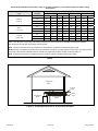
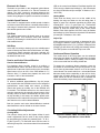
Figure 9. Equipment in Conned Space
(Inlet Air from Ventilated Attic and Outlet Air to
Outside)
Roof Terminated
Exhaust Pipe
Furnace
Ventilation
Louvers
(Crawl Space)
*Intake Debris Screen Provided
Inlet Air
Minimum
12 in. (305mm)
above Crawl
Space Floor
Coupling or
3 in. to 2 in.
Transition
(Field Provided)
* See Maximum Vent Lengths table
NOTE: The inlet and outlet air openings shall each have a
free area of at least one square inch per 4,000 Btu (645mm
2
per 1.17kW) per hour of the total input of all equipment in the
enclosure.
Figure 10. Equipment in Conned Space
(Inlet Air from Ventilated Crawl Space and Outlet Air
to Outside)

507052-04Page 10 of 53 Issue 1727
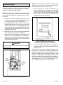
Installation
Setting Equipment
Do not install the furnace on its front, back or in the
horizontal position. See Figure 13. Do no connect the
return air ducts to the back of the furnace. Doing so
will adversely affect the operation of the safety control
devices, which could result in personal injury or death.
WARNING
Select a location that allows for the required clearances
that are listed on the unit nameplate. Also consider gas
supply connections, electrical supply, vent connection,
condensate trap and drain connections, and installation
and service clearances [24 inches (610 mm) at unit front].
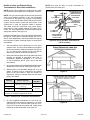
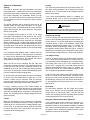
The unit must be level from side to side. Tilt the unit slightly
(maximum 1/2 in. from level) from back to front to aid in the
draining of the heat exchanger. See Figure 12.
Shipping Bolt Removal
NOTE: Units with a 1/2 hp blower motors are equipped
with three exible legs and one rigid leg. The rigid leg
is equipped with a shipping bolt and a at white plastic
washer (rather than the rubber mounting grommet used
with a exible mounting leg). See Figure 11. The bolt and
washer must be removed before the furnace is placed into
operation. After the bolt and washer have been removed,
the rigid leg will not touch the blower housing.
Allow for clearances to combustible materials as indicated
on the unit nameplate. Minimum clearances for closet or
alcove installations are shown in Figure 14.
Figure 11.
Units with 1/2 HP Blower Motor
Blower access panel must be securely in place when
blower and burners are operating. Gas fumes, which
could contain carbon monoxide, can be drawn into
living space resulting in personal injury or death.
WARNING
Figure 12. Setting Equipment
Figure 13.
Improper installation of the furnace can result in
personal injury or death. Combustion and ue products
must never be allowed to enter the return air system or
air in the living space. Use sheet metal screws and joint
tape to seal return air system to furnace.
In platform installations with furnace return, the furnace
should be sealed airtight to the return air plenum. A door
must never be used as a portion of the return air duct
system. The base must provide a stable support and an
airtight seal to the furnace. Allow absolutely no sagging,
cracks, gaps, etc.
For no reason should return and supply air duct systems
ever be connected to or from other heating devices
such as a replace or stove, etc. Fire, explosion, carbon
monoxide poisoning, personal injury and/or property
damage could result.
WARNING
The unit may be installed three ways in downow
applications: on non-combustible ooring, on combustible
ooring using an additive base, or on a reverse-ow
cooling coil cabinet. Do not drag the unit across the oor
in the downow position. Floor and furnace ange damage
will result.
Refer to Figure 14 for clearances in downow applications.

507052-04 Page 11 of 53Issue 1727
Figure 14. Downow Application Installation
Clearances
Top 0
* Front 0
Back 0
Sides 0†
Vent 0
Floor NC‡
* Front clearance in alcove installation must be 24 in. (610
mm). Maintain a minimum of 24 in. (610 mm) for front service
access.
† Allow proper clearances to accommodate condensate trap.
‡ The furnace may be installed on a combustible wood oor if
an optional additive base is installed between the furnace and
the combustible oor.
Installation on Non-Combustible Flooring
1. Cut oor opening keeping in mind clearances listed
on unit rating plate. Also keep in mind gas supply
connections, electrical supply, ue and air intake
connections and sufcient installation and servicing
clearances. See Table 1 for correct oor opening size.
2. Flange warm air plenum and lower the plenum into the
opening.
3. Set the unit over the plenum and seal the plenum to
the unit.
4. Ensure that the seal is adequate.
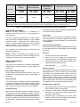
Table 1. Non-Combustible Floor Opening Size
Cabinet Width
Front to Rear Side to Side
in. mm in. mm
B cabinet (17.5”)
19-3/4 502
16-5/8 422
C cabinet (21”) 20-1/8 511
NOTE: Floor opening dimensions listed are 1/4 in. (6 mm)
larger than the unit opening. See dimension drawing on Page
2.
Figure 15.
Installation on Combustible Flooring
1. When unit is installed on a combustible oor, a
downow combustible ooring base must be installed
between the furnace and the oor. The base must be
ordered separately. See Table 2 for opening size to
cut in oor.
The furnace and combustible ooring base shall not be
installed directly on carpeting, tile, or other combustible
material other than wood ooring.
CAUTION
Table 2. Combustible Flooring Base Opening Size
Cabinet
Width
Catalog
Number
Front to Rear Side to Side
in. mm in. mm
B cabinet
(17.5”)
11M60
22 559
18-3/4 476
C cabinet
(21”)
11M61 22-3/4 578
Figure 16.

507052-04Page 12 of 53 Issue 1727
Figure 18.
Figure 19.
Filters
This unit is not equipped with a lter or rack. A eld provided
lter is required for the unit to operate properly. Table 3 lists
recommended lter sizes.
A lter must be in place whenever the unit is operating.
Table 3.
Furnace Cabinet Width Filter Size
17-1/2”
16 x 25 x 1 (1)
21”
Duct System
Use industry-approved standards to size and install the
supply and return air duct system. This will result in a quiet
and low-static system that has uniform air distribution.
NOTE: This furnace is not certied for operation in heating
mode (indoor blower operating at selected heating speed)
with an external static pressure which exceeds 0.8 inches
w.c. Operation at these conditions may result in improper
limit operation.
Supply Air Plenum
If the furnace is installed without a cooling coil, a removable
access panel should be installed in the supply air duct. The
access panel should be large enough to permit inspection
(by reected light) of the heat exchanger for leaks after the
2. After opening is cut, set the combustible ooring base
into opening.
3. Check berglass strips on the combustible ooring
base to make sure they are properly glued and
positioned.
4. Lower supply air plenum into the combustible ooring
base until plenum anges seal against berglass
strips.
NOTE: Be careful not to damage berglass strips.
Check for a tight seal.
5. Set the furnace over the plenum.
6. Ensure that the seal between the furnace and plenum
is adequate.
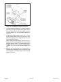
Installation on Cooling Coil Cabinet
NOTE: Downow combustible ooring kit is not used.
1. Refer to reverse-ow coil installation instructions for
correctly sized opening in oor and installation of
cabinet.
2. When cooling cabinet is in place, set and secure the
furnace according to the instructions that are provided
with the cooling coil. Secure the furnace to the cabinet.
3. Seal the cabinet and check for air leaks.
Figure 17.
Return Air Opening - Downow Units
Return air may be brought in only through the top opening of
a furnace installed in the downow position. The following
steps should be taken when installing plenum:
1. Bottom edge of plenum should be anged with a
hemmed edge (see Figure 18 or Figure 19).
2. Sealing strips should be used to ensure an airtight
seal between the cabinet and the plenum.
3. In all cases, plenum should be secured to top of
furnace using sheet metal screws.
4. Make certain that an adequate seal is made.

507052-04 Page 13 of 53Issue 1727
furnace is installed. The furnace access panel must always
be in place when the furnace is operating and it must not
allow leaks into the supply air duct system.
Return Air Plenum
NOTE: Return air must not be drawn from a room where
this furnace, or any other gas-fueled appliance (i.e., water
heater), or carbon monoxide-producing device (i.e., wood
replace) is installed.
When return air is drawn from a room, a negative pressure
is created in the room. If a gas appliance is operating in
a room with negative pressure, the ue products can be
pulled back down the vent pipe and into the room. This
reverse ow of the ue gas may result in incomplete
combustion and the formation of carbon monoxide gas.
This toxic gas might then be distributed throughout the
house by the furnace duct system.
Use berglass sealing strips, caulking, or equivalent
sealing method between the plenum and the furnace
cabinet to ensure a tight seal. If a lter is installed, size the
return air duct to t the lter frame.
Pipe & Fittings Specications
All pipe, ttings, primer and solvent cement must conform
with American National Standard Institute and the American
Society for Testing and Materials (ANSI/ASTM) standards.
The solvent shall be free owing and contain no lumps,
undissolved particles or any foreign matter that adversely
affects the joint strength or chemical resistance of the
cement. The cement shall show no gelation, stratication,
or separation that cannot be removed by stirring. Refer to
Table 4 below for approved piping and tting materials.
Solvent cements for plastic pipe are ammable liquids
and should be kept away from all sources of ignition.
Do not use excessive amounts of solvent cement when
making joints. Good ventilation should be maintained to
reduce re hazard and to minimize breathing of solvent
vapors. Avoid contact of cement with skin and eyes.
CAUTION
The exhaust and intake connections are made of PVC.
Use PVC primer and solvent cement when using PVC
vent pipe. When using ABS vent pipe, use transitional
solvent cement to make connections to the PVC tting
in the unit.
IMPORTANT
Table 4.
Piping and Fittings Specications
Schedule 40 PVC (Pipe) D1785
Schedule 40 PVC (Cellular Core Pipe) F891
Schedule 40 PVC (Fittings) D2466
Schedule 40 CPVC (Pipe) F441
Schedule 40 CPVC (Fittings) F438
SDR-21 PVC or SDR-26 PVC (Pipe) D2241
SDR-21 CPVC or SDR-26 CPVC (Pipe) F442
Schedule 40 ABS Cellular Core DWV
(Pipe)
F628
Schedule 40 ABS (Pipe) D1527
Schedule 40 ABS (Fittings) D2468
ABS-DWV (Drain Waste & Vent)
(Pipe & Fittings)
D2661
PVC-DWV (Drain Waste & Vent)
Pipe & Fittings)
D2665
PRIMER & SOLVENT CEMENT
ASTM
SPECIFICATION
PVC & CPVC Primer F656
PVC Solvent Cement D2564
CPVC Solvent Cement F493
ABS Solvent Cement D2235
PVC/CPVC/ABS All Purpose Cement For
Fittings & Pipe of the same material
D2564, D2235,
F493
ABS to PVC or CPVC Transition Solvent
Cement
D3138
CANADA PIPE & FITTING & SOLVENT
CEMENT
MARKING
PVC & CPVC Pipe and Fittings
ULCS636PVC & CPVC Solvent Cement
ABS to PVC or CPVC Transition Cement
POLYPROPYLENE VENTING SYSTEM
ULC-S636
PolyPro® by Duravent
InnoFlue® by Centrotherm ULC-S636
ECCO Polypropylene Vent
TM
ULC-S636
Use PVC primer and solvent cement or ABS solvent
cement meeting ASTM specications, refer to Table 4.
As an alternate, use all purpose cement, to bond ABS,
PVC, or CPVC pipe when using ttings and pipe made of
the same materials. Use transition solvent cement when
bonding ABS to either PVC or CPVC.
Low temperature solvent cement is recommended during
cooler weather. Metal or plastic strapping may be used as
vent pipe hangers. Uniformly apply a liberal coat of PVC
primer for PVC or use a clean dry cloth for ABS to clean
inside socket surface of tting and male end of pipe to
depth of tting socket.
Canadian Applications Only
Pipe, ttings, primer and solvent cement used to vent
(exhaust) this appliance must be certied to ULC S636 and
supplied by a single manufacturer as part of an approved

507052-04Page 14 of 53 Issue 1727
vent (exhaust) system. When bonding the vent system to
the furnace, use ULC S636 approved One-Step Transition
Cement to bond the pipe to the ue collar. In addition, the
rst three feet of vent pipe from the furnace ue collar must
be accessible for inspection.
Table 5 lists the available exhaust termination kits. All vent
terminations are PVC.
Joint Cementing Procedure
All cementing of joints should be done according to the
specications outlined in ASTM D 2855.
NOTE: A sheet metal screw may be used to secure the
intake pipe to the connector, if desired. Use a drill or self
tapping screw to make a pilot hole.
DANGER OF EXPLOSION!
Fumes from PVC glue may ignite during system check.
Allow fumes to dissipate for at least 5 minutes before
placing unit into operation.
DANGER
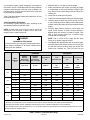
Table 5. Outdoor Termination Kits Usage
Capacity
VENT
PIPE DIA.
(in.)
STANDARD CONCENTRIC
Outdoor
Exhaust
Accelerator
(Dia. X Length)
Outdoor
Exhaust
Accelerator
(Dia. X Length)
Flush Mount
Kit
1-1/2"
Concentric Kit
2" Concentric
Kit
3" Concentric
Kit
1-1/2" x12" 2" x12" 51W11**
71M80
OR
+44W92++
69M29
OR
+44W92++
60L46
OR
44W93+
045
2 YES YES YES
2-1/2" YES YES YES
3 YES YES YES
070
2 YES YES YES
2-1/2" YES YES YES
3 YES YES YES
090
2 YES YES YES YES
2-1/2" YES YES YES YES
3 YES YES YES YES
110
2 YES YES YES YES
2-1/2" YES YES YES YES
3 YES YES YES YES
* Requires eld provided end installed 1-1/2” exhaust accelerator.
** Kit 51W11 is provided with a 1-1/2” accelerator which must be used for all 45,000 and 70,000 furnace installations.
+Termination kits 44W92, 44W93, 30G28 & 81J20 approved for use in Canadian installations to meet CSAB149.
++The 44W92 Concentric kit is provided with a 1-1/2” accelerator which must be installed on the exhaust outlet when this kit is used
with the 45,000 and 70,000 furnaces.
1. Measure and cut vent pipe to desired length.
2. Debur and chamfer end of pipe, removing any ridges
or rough edges. If end is not chamfered, edge of pipe
may remove cement from tting socket and result in a
leaking joint.
3. Clean and dry surfaces to be joined.
4. Test t joint and mark depth of tting on outside of pipe.
5. Uniformly apply a liberal coat of PVC primer for PVC
or use a clean dry cloth for ABS to clean inside socket
surface of tting and male end of pipe to depth of tting
socket.
6. Promptly apply solvent cement to end of pipe and
inside socket surface of tting. Cement should be
applied lightly but uniformly to inside of socket. Take
care to keep excess cement out of socket. Apply
second coat to end of pipe.
NOTE: Time is critical at this stage. Do Not allow
Primer to dry before applying cement.
7. Immediately after applying last coat of cement to pipe,
and while both inside socket surface and end of pipe
are wet with cement, forcefully insert end of pipe into
socket until it bottoms out. Turn PVC pipe 1/4 turn

507052-04 Page 15 of 53Issue 1727
during assembly (but not after pipe is fully inserted) to
distribute cement evenly. Do not turn ABS or cellular
core pipe.
NOTE: Assembly should be completed within 20
seconds after last application of cement. Hammer
blows should not be used when inserting pipe.
8. After assembly, wipe excess cement from pipe at end
of tting socket. A properly made joint will show a bead
around its entire perimeter. Any gaps may indicate
an improper defective assembly due to insufcient
solvent.
9. Handle joints carefully until completely set.
Venting Practices
Figure 20. Piping Suspension Guidelines
Removal of the Furnace from Common Vent
In the event that an existing furnace is removed from
a venting system commonly run with separate gas
appliances, the venting system is likely to be too large to
properly vent the remaining attached appliances.
Conduct the following test while each appliance is operating
and the other appliances (which are not operating) remain
connected to the common venting system. If the venting
system has been installed improperly, you must correct the
system as indicated in the general venting requirements
section.
CARBON MONOXIDE POISONING HAZARD
Failure to follow the steps outlined below for each
appliance connected to the venting system being
placed into operation could result in carbon monoxide
poisoning or death.
The following steps shall be followed for each appliance
connected to the venting system being placed into
operation, while all other appliances connected to the
venting system are not in operation.
WARNING
1. Seal any unused openings in the common venting
system.
2. Inspect the venting system for proper size and
horizontal pitch. Determine that there is no blockage,
restriction, leakage, corrosion, or other deciencies
which could cause an unsafe condition.
3. Close all building doors and windows and all doors
between the space in which the appliances remaining
connected to the common venting system are located
and other spaces of the building. Turn ON clothes
dryers and any appliances not connected to the
common venting system. Turn ON any exhaust fans,
such as range hoods and bathroom exhausts, so they
will operate at maximum speed. Do not operate a
summer exhaust fan. Close replace dampers.
4. Follow the lighting instructions. Turn ON the appliance
that is being inspected. Adjust the thermostat so that
the appliance operates continuously.
5. After the main burner has operated for 5 minutes, test
for leaks of ue gases at the draft hood relief opening.
Use the ame of a match or candle.
6. After determining that each appliance connected to
the common venting system is venting properly, (step
3) return all doors, windows, exhaust fans, replace
dampers, and any other gas burning appliances to
their previous mode of operation.
7. If a venting problem is found during any of the
preceding tests, the common venting system must be
modied to correct the problems.
Resize the common venting system to the minimum vent
pipe size determined by using the appropriate tables in
Appendix G. These are in the current standards of the
National Fuel Gas Code ANSI Z223.1.

507052-04Page 16 of 53 Issue 1727
Figure 21.
1. In areas where piping penetrates joist or interior walls,
hole must be large enough to allow clearance on all
sides of pipe through center of hole using a hanger.
2. When furnace is installed in a residence where unit
is shut down for an extended period of time, such
as a vacation home, make provisions for draining
condensate collection trap and lines.
Exhaust Piping
Route piping to outside of structure. Continue with
installation following instructions given in piping termination
section.
Do not discharge exhaust into an existing stack or
stack that also serves another gas appliance. If vertical
discharge through an existing unused stack is required,
insert PVC pipe inside the stack until the end is even
with the top or outlet end of the metal stack.
CAUTION
The exhaust vent pipe operates under positive pressure
and must be completely sealed to prevent leakage of
combustion products into the living space.
CAUTION
Vent Piping Guidelines
This gas furnace can be installed as either a Non-Direct
Vent or a Direct Vent gas central furnace.
NOTE: In non-Direct Vent installations, combustion air is
taken from indoors and ue gases are discharged outdoors.
In Direct Vent installations, combustion air is taken from
outdoors and ue gases are discharged outdoors.
Intake and exhaust pipe sizing - Size pipe according to
Table 6 and Table 7A through Table 7C. Table 6 lists the
minimum vent pipe lengths permitted. Table 7A through
Table 7C lists the maximum pipe lengths permitted.
Regardless of the diameter of pipe used, the standard roof
and wall terminations described in section Exhaust Piping
Terminations should be used. Exhaust vent termination
pipe is sized to optimize the velocity of the exhaust gas as
it exits the termination.
Table 6. Minimum Vent Pipe Lengths
Capacity Min. Vent Length*
045, 070, 090, 110
15 ft. or
5 ft. plus 2 elbows or
10 ft. plus 1 elbow
* Any approved termination may be added to the minimum
length listed.
In some applications which permit the use of several
different sizes of vent pipe, a combination vent pipe may
be used. Contact Allied Air Technical Service for assistance
in sizing vent pipe in these applications.
Do not use screens or perforated metal in exhaust or
intake terminations. Doing so will cause freeze-ups and
may block the terminations.
IMPORTANT

507052-04 Page 17 of 53Issue 1727
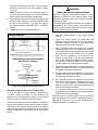
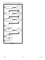
Use the following steps to correctly size vent pipe diameter.
Figure 22.
045, 070,
090, 110
Standard or
Concentric?
See Table 5
Intake or
Exhaust?
2”, 2-1/2”
or 3”
Furnace capacity?
1
Which termination?
2
Which needs most
elbows?
3
How many?
4
Desired pipe size?
5
What is the altitude?
6
Use Table 7 to find
max pipe length.
7

507052-04Page 18 of 53 Issue 1727
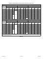
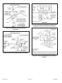
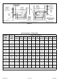
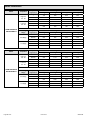
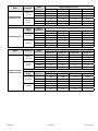
A95DF2V & 95G2DFV Maximum Allowable Intake or Exhaust Vent Length in Feet
Standard Termination at Elevation 0 - 4,500 ft
Number of
90° Elbows
Used
2nd Pipe 2-1/2" Pipe 3" Pipe
Capacity Capacity Capacity
045 070 090 110 045 070 090 110 045 070 090 110
1 66 51 29 9 100 100 78 43 123 122 103 103
2 61 46 24
n/a
95 95 73 38 118 117 98 98
3 56 41 19 90 90 68 33 113 112 93 93
4 51 36 14 85 85 63 28 108 107 88 88
5 46 31 9 80 80 58 23 103 102 83 83
6 41 26
n/a
75 75 53 18 98 97 78 78
7 36 21 70 70 48 13 93 92 73 73
8 31 16 65 65 43 8 88 87 68 68
9 26 11 60 60 38
n/a
83 82 63 63
10 21 6 55 55 33 78 77 58 58
Standard Termination at Elevation 4,501 - 10,000 ft
Number of
90° Elbows
Used
2nd Pipe 2-1/2" Pipe 3" Pipe
Capacity Capacity Capacity
045 070 090 110 045 070 090 110 045 070 090 110
1 66 51 29
n/a
100 100 78 43 123 122 103 103
2 61 46 24 95 95 73 38 118 117 98 98
3 56 41 19 90 90 68 33 113 112 93 93
4 51 36 14 85 85 63 28 108 107 88 88
5 46 31 9 80 80 58 23 103 102 83 83
6 41 26
n/a
75 75 53 18 98 97 78 78
7 36 21 70 70 48 13 93 92 73 73
8 31 16 65 65 43 8 88 87 68 68
9 26 11 60 60 38
n/a
83 82 63 63
10 21 n/a 55 55 33 78 77 58 58
*Size intake and exhaust pipe length separately. Values in table are for intake OR Exhaust, not combined total. Both Intake and
Exhaust must be same pipe size.
Table 7A.
Table 7.

507052-04 Page 19 of 53Issue 1727
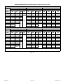
A95DF2V & 95G2DFV Maximum Allowable Intake or Exhaust Vent Length in Feet
Concentric Termination at Elevation 0 - 4,500 ft
Number of
90° Elbows
Used
2nd Pipe 2-1/2" Pipe 3" Pipe
Capacity Capacity Capacity
045 070 090 110 045 070 090 110 045 070 090 110
1 58 43 27 7 90 90 74 39 106 106 99 99
2 53 38 22
n/a
85 85 69 34 101 101 94 94
3 48 33 17 80 80 64 29 96 96 89 89
4 43 28 12 75 75 59 24 91 91 84 84
5 38 23 7 70 70 54 19 86 86 79 79
6 33 18
n/a
65 65 49 14 81 81 74 74
7 28 13 60 60 44 9 76 76 69 69
8 23
n/a
55 55 39
n/a
71 71 64 64
9 18 50 50 34 66 66 59 59
10 13 45 45 29 61 61 54 54
Concentric Termination at Elevation 4,501 - 10,000 ft
Number of
90° Elbows
Used
2nd Pipe 2-1/2" Pipe 3" Pipe
Capacity Capacity Capacity
045 070 090 110 045 070 090 110 045 070 090 110
1 58 43 27
n/a
90 90 74 39 106 106 99 99
2 53 38 22 85 85 69 34 101 101 94 94
3 48 33 17 80 80 64 29 96 96 89 89
4 43 28 12 75 75 59 24 91 91 84 84
5 38 23 7 70 70 54 19 86 86 79 79
6 33 18
n/a
65 65 49 14 81 81 74 74
7 28 13 60 60 44 9 76 76 69 69
8 23 8 55 55 39
n/a
71 71 64 64
9 18
n/a
50 50 34 66 66 59 59
10 13 45 45 29 61 61 54 54
*Size intake and exhaust pipe length separately. Values in table are for intake OR Exhaust, not combined total. Both Intake and
Exhaust must be same pipe size.
Table 7B.

507052-04Page 20 of 53 Issue 1727
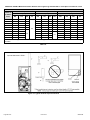
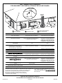
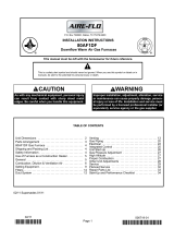
Figure 23. Typical Exhaust Pipe Connections
A95DF2V & 95G2DFV Maximum Allowable Exhaust Vent Length Using Ventilated Attic or Crawl Space for Intake Air in Feet
Standard Termination at Elevation 0 - 10,000 ft
Number of
90° Elbows
Used
2nd Pipe 2-1/2" Pipe 3" Pipe
Capacity Capacity Capacity
045 070 090 110 045 070 090 110 045 070 090 110
1 56 41 24
n/a
85 85 63 28 103 102 83 83
2 51 36 19 80 80 58 23 98 97 78 78
3 46 31 14 75 75 53 18 93 92 73 73
4 41 26 9 70 70 48 13 88 87 68 68
5 36 21 4 65 65 43 8 83 82 63 63
6 31 16
n/a
60 60 38 3 78 77 58 58
7 26 11 55 55 33
n/a
73 72 53 53
8 21 6 50 50 28 68 67 48 48
9 16 1 45 45 23 63 62 43 43
10 11 n/a 40 40 18 58 57 38 38
NOTE: Additional vent pipe and elbows used to terminate the vent pipe outside the structure must be included in the total vent length
calculation.
Table 7C.
Page is loading ...
Page is loading ...
Page is loading ...
Page is loading ...
Page is loading ...
Page is loading ...
Page is loading ...
Page is loading ...
Page is loading ...
Page is loading ...
Page is loading ...
Page is loading ...
Page is loading ...
Page is loading ...
Page is loading ...
Page is loading ...
Page is loading ...
Page is loading ...
Page is loading ...
Page is loading ...
Page is loading ...
Page is loading ...
Page is loading ...
Page is loading ...
Page is loading ...
Page is loading ...
Page is loading ...
Page is loading ...
Page is loading ...
Page is loading ...
Page is loading ...
Page is loading ...
Page is loading ...
-
 1
1
-
 2
2
-
 3
3
-
 4
4
-
 5
5
-
 6
6
-
 7
7
-
 8
8
-
 9
9
-
 10
10
-
 11
11
-
 12
12
-
 13
13
-
 14
14
-
 15
15
-
 16
16
-
 17
17
-
 18
18
-
 19
19
-
 20
20
-
 21
21
-
 22
22
-
 23
23
-
 24
24
-
 25
25
-
 26
26
-
 27
27
-
 28
28
-
 29
29
-
 30
30
-
 31
31
-
 32
32
-
 33
33
-
 34
34
-
 35
35
-
 36
36
-
 37
37
-
 38
38
-
 39
39
-
 40
40
-
 41
41
-
 42
42
-
 43
43
-
 44
44
-
 45
45
-
 46
46
-
 47
47
-
 48
48
-
 49
49
-
 50
50
-
 51
51
-
 52
52
-
 53
53


ROYALTON 95G2DF110CV20 Installation guide
- Type
- Installation guide
- This manual is also suitable for
Ask a question and I''ll find the answer in the document
Finding information in a document is now easier with AI
Related papers
-
 Allied Air 92G1DF Installation guide
-
Allied 80G1DF090BE16 Installation guide
-
ROYALTON 80G1DF045AP12 Installation guide
-
-
-
Allied 96G2DF070BV16 Installation guide
-
COMFORT-AIRE 96G2UH110CV20 Installation guide
-
-
-
Allied 96G2UH110CV20 Specification

Other documents
-
Lennox SLP98DFV SERIES User manual
-
Lennox ML193DF User manual
-
Lennox DAVE LENNOX SIGNATURE COLLECTION GAS FURNACE User manual
-
 Aire-Flo 80AF1DF Owner's manual
-
-
-
-
Gibraltar Building Products CHADS-1/8 Installation guide
-
-
