Page is loading ...

Improper installation of the furnace can result in
personal injury or death. Combustion and ue products
must never be allowed to enter the return air system or
air in the living space. Use sheet metal screws and joint
tape to seal return air system to furnace.
In platform installations with furnace return, the furnace
should be sealed airtight to the return air plenum. A door
must never be used as a portion of the return air duct
system. The base must provide a stable support and an
airtight seal to the furnace. Allow absolutely no sagging,
cracks, gaps, etc.
For no reason should return and supply air duct systems
ever be connected to or from other heating devices
such as a replace or stove, etc. Fire, explosion, carbon
monoxide poisoning, personal injury and/or property
damage could result.
WARNING
Figure 10. Installation Clearances
*Front 0
Back 0
Sides 0†
Vent 0
Floor NC‡
* Front clearance in alcove installation must be 24 in. (610
mm). Maintain a minimum of 24 in. (610 mm) for front service
access.
† Allow proper clearances to accommodate condensate trap
and vent pipe installation.
‡ The furnace may be installed on a combustible wood oor if
an optional additive base is installed between the furnace and
the combustible oor.
Installation on Non-Combustible Flooring
See Figure 11
1. Cut oor opening keeping in mind clearances listed
on unit rating plate. Also keep in mind gas supply
connections, electrical supply, ue and air intake
connections and sufcient installation and servicing
clearances. See Table 1 for correct oor opening size.
2. Flange warm air plenum and lower the plenum into the
opening.
3. Set the unit over the plenum and seal the plenum to
the unit.
4. Ensure that the seal is adequate.
Table 1. Non-Combustible Floor Opening Size
Cabinet Width
Front to Rear Side to Side
in. mm in. mm
B Cabinet (17.5”) 19-3/4 502 16-5/8 422
C Cabinet (21”) 19-3/4 502 20-1/8 511
NOTE: Floor opening dimensions listed are 1/4 inch (6 mm)
larger than the unit opening. See dimension drawing on page
2.
Figure 11
Installation on Combustible Flooring
See Figure 12 (Combustible Floor Base Models
11M59, 11M60, 11M61)
1. When unit is installed on a combustible floor, a
downflow combustible flooring base must be installed
between the furnace and the floor. The base must be
ordered separately. See Table 2 for opening size to
cut in floor.
The furnace and combustible flooring base shall not be
installed directly on carpeting, tile, or other
combustible material other than wood flooring.
CAUTION
Installation of Combustible Flooring Base
Referenced in downflow installation instructions
Section is shown in BLUE type below.

Table 2. Combustible Flooring Base Opening Size
Cabinet
Width
Catalog
Number
Front to
Rear
Side to Side
in. mm in. mm
B Cabinet
(17.5”)
11M60 22 559 18-3/4 476
C Cabinet
(21”)
11M61 22 559 22-3/4 578
Figure 12
2. After opening is cut, set the combustible flooring base
into opening.
3. Check fiberglass strips on the combustible flooring
base to make sure they are properly glued and
positioned.
4. Lower supply air plenum into the combustible flooring
base until plenum flanges seal against fiberglass
strips.
NOTE: Be careful not to damage fiberglass strips.
Check for a tight seal.
5. Set the furnace over the plenum.
6. Ensure that the seal between the furnace and plenum
is adequate.
Installation on Cooling Coil Cabinet
See Figure 13
NOTE: Downow combustible ooring kit is not used.
1. Refer to reverse ow coil installation instructions for
correctly sized opening in oor and installation of
cabinet.
2. When cooling cabinet is in place, set and secure the
furnace according to the instructions that are provided
with the cooling coil. Secure the furnace to the cabinet.
3. Seal the cabinet and check for air leaks.
Figure 13
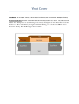
Return Air Opening - Downow Units
Return air may be brought in only through the top opening of
a furnace installed in the downow position. The following
steps should be taken when installing plenum:
1. Bottom edge of plenum should be anged with a
hemmed edge (See Figure 14 or 15).
2. Sealing strips should be used to ensure an airtight
seal between the cabinet and the plenum.
3. In all cases, plenum should be secured to top of
furnace using sheet metal screws.
4. Make certain that an adequate seal is made.
Figure 14
Figure 15
/