Page is loading ...

Manual
PD 400

- 3 -
6FK
QLWWJ
HVF
KZ
LQG
LJNHLW
$
OXP
LQLXP
²
0
HVVLQJ
²
6WDK
O
²
$
XWRP
DWHQ
VWD
KO
²
K
QLWWJ
HVF
KZ
LQG
LJN
²
²
²
²
P
0
HVV
WDK
0
6W
6FK
QLWWJ
HVF
KZ
LQG
LJNHLW
$
6FK
QLWWJ
HVF
KZ
LQG
LJ
$
OXP
LQLXP
0
6
QLWWJ
$
OXP
LQLX
0
HVVLQ
6
²
²
²
6
$
VLQJ
$
0
0
²
²
6
$
X
KZ
LQG
P
XWRP
DWH
X
DWHQ
K
QLWWJ
HVF
KZ
LQG
LJN
6W
$
X
JNHLW
WJ
HVF
KZ
L
LXP
V
WDK
O
XWR
J
HVF
KZ
L
XP
$
XWRP
DWHQ
VWD
KO
1
3
4
5
2
80/160 min
-1
330/660 min
-1
1400/2800 min
-1
i
ndigkeit
100–200
70–100
20–40
40– 70
1
0
1710
16
26
54
81
0
7
3
4
1
2500
24
39
79
118
157
196
236
275
314
Ø D
L = 3 xD
1
2
7
3
18
6
5
4
2
45
6
1
3
Fig. 2
Fig. 3
Fig. 1
Fig. 6Fig. 5Fig. 4
Fig. 9
Fig. 7 Fig. 8
33
32

- 4 -
0
15
30
15
30
1
2
3
0
2
2
4
4
6
6
8
8
0
10
10
20
20
30
30
11°
A
B
Fig. 11a
n
d
ig
ke
it
1
0
0
–
2
0
0
7
0
–
10
0
2
0
–
40
4
0
– 7
0
0
1710
16
2
6
5
4
8
1
7
4
2500
24
39
79
118
157
196
236
275
3
14
1
2
Fig. 15
Fig. 11
I
O
Fig. 14
Fig. 12 Fig. 13
4
2
13
5
1
3
5
Fig. 18
Fig. 16
Fig. 17
11
22
Fig. 19 Fig. 20

mm
0.07 0.14
W - /30 - /30
Z1 20/60 40/60
Z2 70/25 70/25
L - /75 - /75
Spindle Speeds [1/min]
Motor 1400/min Motor 2800/min
80 160
330 660
1400 2800
n/1"
WZ1 Z2 L
10 36 -/70 40/25 34/-
11 36 -/75 30/20 35/-
12 36 -/75 40/34 30/-
14 36 -/70 40/34 35/-
16 36 -/65 30/50 -/34
18 36 -/65 40/34 45/-
20 36 -/60 40/34 50/-
22 36 -/60 40/34 55/-
24 36 -/55 40/34 60/-
28 36 -/55 40/34 70/-
32 36 -/65 30/34 60/-
36 36 -/70 20/34 45/-
40 36 -/70 20/34 50/-
48 36 -/65 20/34 60/-
mm
WZ1 Z2 L
0,2 30 -/45 20/60 75/-
0,25 30 -/45 25/60 75/-
0,3 30 -/55 20/50 60/-
0,35 30 -/45 35/60 75/-
0,4 30 -/55 20/45 50/-
0,45 30 -/60 20/40 50/-
0,5 30 -/65 20/30 60/-
0,6 30 -/65 20/30 50/-
0,7 30 -/55 35/45 50/-
0,75 30 -/55 30/40 45/-
0,8 30 -/55 40/45 50/-
0,9 30 -/70 20/25 40/-
1,0 30 -/50 40/30 60/-
1,25 30 -/55 50/30 60/-
1,50 30 -/55 40/20 60/-
1,75 30 -/70 35/20 45/-
2,0 30 -/55 50/25 45/-
2,5 30 -/55 50/20 45/-
3,0 30 -/65 40/20 30/-
VV
VV
VV
- 5 -
4
2
4
1
3
6
5
1
3
4
2
Fig. 22
Fig. 23
Fig. 24
Fig. 21
Fig. 25

- 14 -
Translation of the Original Operating
Instructions
Foreword
Dear Customer,
With the PROXXON PD 400 lathe, you own a carefully con-
structed machine made by specialists for whom precision has
become a tradition. This machine is highly versatile in its
applications. In addition, please see the well-designed
accessories programme.
To use the machine correctly, it is essential that you carefully
read and observe these instructions. This applies not only to
beginners, but also to professionals. Please also carefully read
the chapter on maintenance. If used carefully and maintained
properly (including regular oiling), the machine will deliver pre-
cise results over a long service life.
We hope that you enjoy reading the instructions and your first
turning attempts with the PD 400.
We reserve the right to make modifications in the interest of
technical progress.
Contents
Safety regulations (see enclosed booklet) Page
Key 14
Description of the machine and scope of delivery 15
Technical data 15
Installation and setting up 15
Operation 15
1. Switching on the machine 16
2. Quick adjustment of the support 16
3. Switching on the automatic feed 16
4. Moving the turning tool (longitudinal
and lateral turning) 16
5. Determining the correct spindle speed 17
6. Setting the spindle speeds 17
7. Selecting the turning tool 17
8. Inserting the turning tool in the tool holder 17
9. Clamping in the chuck 17
10. Example of longitudinal turning 18
11. Taper turning 18
12. Grooving and parting off a workpiece 18
13. Machining longer work pieces with
tailstock and centre 18
14. Changing the feed 19
15. Fitting change gears for thread cutting 19
16. Thread cutting with the turning tool 19
17. Cutting left-hand threads 19
Maintenance
18. General 20
19. Setting the guide play 20
20. Main spindle 20
21. Predetermined breaking point of the leadscrew 20
22. Disposal 20
Accessories for Lathe PD 400 20
21. Centre turning attachment 20
22. 4-jaw chuck with individually adjustable jaws 21
23. 4-jaw chuck (concentrically clamping) 21
24. Collet chuck unit and collet chucks 21
25. Fixed steady rest 21
26. Travelling steady rest 21
27. Faceplate with clamps 21
Spare parts list 102
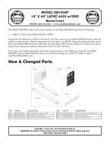
Key (Fig. 1):
1. Main spindle
2. Lathe chuck
3. Multiple tool holder with tool holder element
4. Rotating centre
5. Flange surface for milling unit PF 400 (optional)
6. Sleeve
7. Clamp screw for sleeve
8. Tailstock
9. Sleeve adjusting handwheel
10. Handwheel for leadscrew
11. Clamp screw for tailstock
12. Holes for tabletop mounting
13. Leadscrew
14. Adjusting handwheel for top slide
15. Top slide
16. Support
17. Cross-slide
18. Adjusting handwheel for cross-slide
19. Lock box
20. Engaging lever for leadscrew nut
21. Handwheel for quick adjustment
22. Leadscrew switch
23. Gearbox
24. Direction switch for anti-clockwise rotation - stop - clock-
wise rotation
25. Main switch
26. Function display
27. Stepper switch for speed adjustment
28. Allen key
29. Open-ended spanner
30. Lathe chuck spanner
31. Toothed chuck
32. Change gear set
33. Tool holder element
GB

- 15 -
Description of the machine and scope
of delivery
The PROXXON PD 400 lathe is an extendable system
characterised by:
– rugged, ribbed lathe bed with prismatic guide
– 6 spindle speeds (switch for 2 motor speeds and
3 additional gears)
– Quick adjustment of the support by easy-to-use crank
– Automatic feed
The scope of delivery includes:
– Precision triple-jaw chuck (100 mm diameter)
– Rotating centre
– Toothed chuck (for up to 10 mm)
– Change gear set for two feed speeds (0.07mm/rev. and
0.14mm/rev.), 19 metric thread pitches and also inch
thread pitches from 10 to 48 threads.
– Auxiliary tools
– Multiple tool holder with 2 tool holder elements
– Left-hand thread cutting device
– Chuck guard
–
Two spare shear pins
Technical data:
Machine
Centre height 85 mm
Centre distance 400 mm
Max. workpiece diameter
above support 116 mm
Spindle aperture 20.5 mm
Main spindle, chuck side MK3
Spindle speeds Stage I 80 rpm; 330 rpm;
1400 rpm
Stage II: 160 rpm; 660 rpm;
2800 rpm
Lathe chuck Inner jaws 3-33 mm
Outer jaws 32-83 mm
Refer to the instructions for information on the chuck.
Automatic feed 0.07 or 0.14 mm/rev.
Thread pitches see table in gearbox
Tailstock sleeve stroke 30 mm/MK 2
Tool holder 10 x 10 mm
Dimensions 900x400x300 mm (LxWxH)
Weight 45 kg
Noise ≤ 70 dB (A)
For use in dry environments only
Please do not dispose off the machine!
Motor
Voltage 220-240 volts, 50/60 Hz
Stage I Stage II
Speed 1400 rpm 2800 rpm
Output power 0.25 kW 0.55 kW
Consumption 2.1 A 3.9 A
Installation and setting up:
Note:
The machine must mot be lifted by the gearbox 23 (Fig. 1) or
by the cover cap of the motor when transporting. The plastic
caps could break.
The supporting surface must be flat and sufficiently strong to
absorb the vibration generated during work. The machine
must be fastened to the surface using the holes 12 (Fig. 1)
provided for this purpose. Ensure that the power cable is
outside the danger zone.
Mount the lathe chuck 2 (Fig. 1) on the main spindle with the
3 screws. Ensure that the chuck seating is free of dust.
Refer to the separately enclosed clamping chuck instructions
for information on using the chuck.
All polished metal parts are supplied with a corrosion protec-
tion coating. This is not intended as a lubricant, but as a pre-
servative only. It must be rinsed off, e.g. with petroleum, befo-
re the machine is used. All guides must be checked and
adjusted if necessary. (See also Chapter „Maintenance”.)
The polished guides and spindles must then be well lubricated
with a suitable machine oil. The chuck guard can then be
mounted.
Note:
Do not oil the any part of the mechanical drive mechanism (belt
pulleys, belts, gearwheels). If there is any excessive noise,
however, it could be advisable to apply a light coat of Molykote
grease to the gearwheels.
Operating:
Attention!
Before turning on the machine, check that the screws of chuck
2 (Fig. 1) are tightened properly, that the chuck key has been
removed, and that support 16 (Fig. 1) is at a safe distance from
the chuck.
Attention!
Practice without a workpiece clamped in the chuck first. Be sure
to ensure that the turning jaws are tightened securely since they
could be loosened by centrifugal force if there is no resistance.
Practice first by running the machine at low speeds.
Please note that the turning chuck has been oiled slightly and
could throw off oil when run for the first time.
Attention!
Please note that due to the motor design, the motor could
become very hot if allowed to idle for an extended length of
time. Although this does not indicate that the motor is defective,
it is advisable nevertheless to avoid situations of this kind by not
allowing the motor to idle unnecessarily.

- 16 -
Switching on the machine
1. Set direction switch 1 (Fig. 2) to "0".
2. Disengage the leadscrew (turn leadscrew switch 2 to the
left).
3. Set a low speed (stepper switch 3 to I).
4. Switch on the machine at the main switch 4. The function
display 5 now lights.
5. Turn the direction switch to the right. The lathe chuck now
rotates in the working direction.
Quick adjustment of the support
The support can be quickly moved via handwheel 1 (Fig. 3).
For this purpose, the support must first be disengaged.
Important
Loosen clamping screw 2 by half a turn beforehand.
1. Push lever 3 upwards.
2. Adjust the support by turning handwheel 1
(1 revolution = 10.5 mm)
Switching on the automatic feed
1. Set machine to "0" at direction switch 1 (Fig. 2)
2. Disengage support (push lever 3 (Fig. 3) upwards).
3. Ensure that handwheel 10 (Fig. 1) moves freely because it
moves the leadscrew when engaged.
4. Engage leadscrew (turn leadscrew switch 2 (Fig. 2) to the
right).
5. Switch machine on by setting direction switch to the right.
The leadscrew and the handwheel now also turn.
Important
The automatic feed is not equipped with an automatic cut-off.
Ensure that you disengage the support before it runs against
the lathe chuck.
6. Engage support (push lever 3 (Fig. 3) downwards). The sup-
port now moves in the working direction.
Note
When working, always operate the automatic feed via lever 3
(Fig. 3) only. Only operate the leadscrew switch 2 (Fig. 2) when
the machine is stopped.
Moving the turning tool
(longitudinal turning and lateral turning)
Apart from the quick adjustment of the support and the auto-
matic feed, the turning tool can be moved in 3 different ways.
A. Movement with the leadscrew (longitudinal turning)
1. Disengage leadscrew (turn leadscrew switch 2 (Fig. 2) to
the left).
2. Engage support (push lever 3 (Fig. 3) downwards).
3. Move support using the handwheel 10 (Fig. 1).
1 turn = 1.5 mm
B. Movement of the top slide (longitudinal turning)
1. If required, clamp the support (tighten screw 2 (Fig. 3)).
2. Move top slide with handwheel 4.
1 turn = 1.0 mm.
C. Moving the cross-slide (face turning)
1. If required, clamp the support (tighten screw 2).
2. Move cross-slide with handwheel 5.
1 turn = 1 mm feed = 2 mm change in diameter.

- 17 -
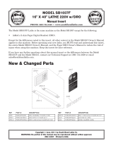
Determining the correct spindle speed
The choice of the correct cutting speed is a decisive factor in
obtaining good results. In the case of longitudinal turning, this
is the peripheral speed of the workpiece. The table on the
gearbox of the machine provides directions for the choice of
the correct cutting speed.
When the cutting speed “Vc” and the workpiece diameter “D”
are known, the required spindle speed „n„ can be calculated
as follows:
n = V
c
x 1000/ (D x 3.14)
Example: An aluminium workpiece with a diameter of 30 mm
is to be turned. The required cutting speed according to the
table is 100 – 180 m/min. Thus: 132 m/min.
n = 132 x 1000/ (30 x 3.14) = 1400 rpm
This result can also be read directly from the table on the
gearbox.
Setting the spindle speeds
One way of changing the spindle speed is by switching the
motor speed (stepper switch 1, Fig. 4). This halves or doubles
the speed. Another way of changing the speed is by changing
the belt transmission.
1. Switch off the machine at the main switch 2 and open gear-
box 3 with the Allen key.
2. Loosen clamping screw 1 (Fig. 5) by half a turn.
3. Turn screw 3 anti-clockwise using Allen key 2. This releases
the intermediate belt pulley 4.
4. Then change the belts as shown in Fig. 6.
5. Remove Allen key 2 and tighten clamping screw 1.
6. Close gearbox 3 (Fig. 4).
Note:
It is possible that the motor will not always start when the
multiple contact switch is set to stage II. In this case, start by
setting the switch to I first and then to stage II.
Selecting the turning tool
There are several different types of turning tool. There follows
a brief explanation (see Fig. 7):
Roughing tools (1) are used to cut away as much material as
possible in a short time (without regard to the finish of the sur-
face of the workpiece).
Smoothing tools or thread chasers (2) are used to achieve a
smooth surface.
Right (3) and left side tools are used for longitudinal and face
turning and to turn out acute angles in a right or left hand
working direction.
Part-off tools (4) are used to start grooves and to cut off
workpieces.
Threading tools (5) to cut external threads.
Internal turning tools (6) are used for turning out.
Inserting the turning tool in the tool holder
The basic equipment of the PD 400 includes a multiple tool
holder (Fig. 8) consisting of tool holder block 1 and two tool
holder elements 2. For good working results, it is essential for
the tool to be set precisely to „the middle„ and that the tur-
ning tool is held short to prevent vibration.
1. Place turning tool 3 in tool holder element 2. Tighten the
two screws 4 securely.
2. Place tool holder element in tool holder block 1. Adjust the
height of the turning tool via nut 5 and lock via nut 6. Adjust
the height of the blade to that of the centrepoint of the tail-
stock.
3. Clamp tool holder element with screw 7.
Note:
The entire holder block can be swivelled by loosening screw 8.
Clamping in the chuck
Attention!
Follow the instructions in the enclosed operator's manual
provided by the manufacturer of the chuck.
Important
If workpieces are only clamped in the lathe chuck without
support by the tailstock, the projection must not be greater
than three times the diameter of the material
(L = 3 x D), see Fig. 9.

- 18 -
Example of longitudinal turning
Longitudinal turning designates the turning of a cylindrical
workpiece parallel to the turning axis. The following paragraph
explains work with the lathe to the beginner using the exam-
ple of longitudinal turning.
Clamp a short workpiece in the lathe chuck as described
above (remove the key from the chuck).
Set the belt transmission to the correct speed (note table on
gearbox and Fig. 6).
Disengage the leadscrew (leadscrew switch 2 (Fig. 2) to left)
and engage the support (lever 3 (Fig. 3) downwards).
Now move the support from the right to the left close to the
workpiece (handwheel 10 (Fig. 1)).
Before switching on the machine, check that the chuck moves
freely by twisting the chuck by hand.
Switch on the machine (direction switch 1 (Fig. 2) to right).
Set the cutting depth by moving the cross-slide (handwheel 5
(Fig. 3)). It is best to start with a cutting depth of 1/10 mm
(4 graduations on the scale).
Now move the support in the working direction by turning the
handwheel 10 (Fig. 1) at the rear. If all settings are correct, the
machine works smoothly and without excessive loading.
Important
Risk of injury. When turning, always keep your fingers away
from the rotating workpiece. Never measure the workpiece
with a calliper gauge or a similar tool when the machine is
running. Do not apply a file or emery cloth to the workpiece
when the machine is running.
Taper turning
To turn tapers, the top slide is adjusted according to the desi-
red angle.
1. Move top slide to the right with handwheel 1 (Fig. 11).
2. Loosen clamping screws 2.
3. Adjust the angle of the top slide and re-tighten the screws.
Note:
The top slide is equipped with a vernier scale (similar to a cal-
liper gauge). The correct angles are indicated on the outer
scale A (Fig. 11a). On the inner scale B, they are compressed
(1 graduation on the inner scale corresponds to 4.5°). The
angle can be read in 5° stages by aligning the zero mark of
the inner scale with the outer scale. If you wish to add 1°, the
“2” on the inner scale must be aligned 10° further outwards
on the outer scale. For 2°, the “4” must be aligned 20° further
outwards etc. In this example, the “2” is aligned with the “20”,
or 10° further outwards than the basic value of 10°. This pro-
duces an angle of 10°+1°=11°.
4. Clamp support with screw 3 (Fig. 11).
5. The feed is advanced via the handwheel of top slide 1.
Note:
A precise taper is only achieved when the height of the
turning tool is adjusted exactly to the centre position.
Grooving and parting off a workpiece
Grooving designates the production of fine grooves. If the
groove is continued to the middle of the workpiece, this is cal-
led parting off. Ensure that the height of the parting-off tool is
adjusted to the centre of the workpiece and clamp the tool as
short as possible. Use a small turning tool and lubricate the
tool with a little machine oil if possible.
Machining longer work pieces with tailstock and
centre
Longer workpieces (chuck projection greater than 3 times the
workpiece diameter) must be held at the right hand end by the
tailstock and the travelling centrepoint. For this purpose,
provide a centrebore on the right hand face:
1. Turn the face of the right hand end carefully.
2. Insert chuck 1 (Fig. 12) in the tailstock and clamp a centring
bit.
3. Move the tailstock to the workpiece and fasten with clam-
ping screw 2.
4. Switch on the machine and make the centrebore using the
sleeve feed (handwheel 4).

- 19 -
You can then replace the chuck with the travelling centrepoint.
Guide the point into the centrebore and close down carefully
until any play is eliminated. Then fasten the sleeve with tommy
screw 3.
Changing the feed
In the standard version, the PD 400 is supplied with a feed of
0.07 mm/rev. To use a faster feed (0.14 mm/rev.), the gear-
wheel of shaft Z1 (5, Fig. 13) with 20 teeth must be replaced
by the gearwheel with 40 teeth in the gearbox. For this purpo-
se, please proceed as follows:
1. Switch off the machine at the main switch 25 (Fig. 1) and
open the gearbox 23.
2. Loosen screw 1 (Fig. 14) slightly and tilt wheel arm 2 down-
wards.
3. Remove clip 3 (Fig. 13).
4. Loosen shaft 4 at the square section by half a turn. Replace
the gearwheel 5 with 20 teeth by one with 40 teeth.
Note:
When changing the gearwheels, always place a strip of news-
paper between the tooth flanks before tightening the shafts.
The thickness of the paper strip should correspond to the
required tooth flank play.
5. Re-tighten the shaft, push on the clip, fold up the wheel
arm and re-tighten screw 1 (Fig. 14).
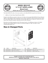
Fitting change gears for thread cutting
With the PD 400, it is possible to turn 19 different metric
threads (see table in the gearbox and Fig. 25) and inch
threads from 10 to 48 threads. To adjust the thread pitches,
the change gears must be exchanged correspondingly.
The change gears for a thread pitch of 1 mm are installed in
Fig. 14.
The table in the gearbox shows: w = 30, Z1 = -/50,
Z2 = 40/30, L = 60/-. w designates the gearwheel on the main
spindle. It is fastened to the main spindle by a stud. Z1 and
Z2 are the two shafts of the intermediate gears. The first
number always designates the front gear of the shaft, the last
number the rear gear. The rear gear with 30 teeth is therefore
firstly pushed onto the shaft Z2 and then the front gear with
40 teeth. On shaft Z1, first install the rear gear with 50 teeth
and then an intermediate ring.
L designates the gear on the leadscrew. Nut 6 must be loose-
ned to change this gear. The compensating disc 7 has exactly
the width of a gearwheel and must be mounted in front of or
behind the gear.
Thread cutting with the turning tool
Note:
For the following operations, the work piece must be machi-
ned completely and have the correct thread outer diameter.
It is advisable to turn a chamfer at the beginning of the thread
and to turn a small groove at the end of the thread. The
thread turning tool must be clamped at an angle of exactly
90°.
Important
When cutting threads, always work at the lowest speed
(80 rpm) because otherwise the feed is too fast (risk of injury).
1. Set the turning tool to the starting position.
2. Engage leadscrew (turn leadscrew switch 1 (Fig. 15) to the
right).
3. Switch on the machine.
4. Advance the turning tool slightly by means of the cross-
slide.
5. Engage the support (lever 2 downwards).
6. When the desired thread length has been reached, retract
the cross-slide and switch off the machine at the direction
switch.
7. Wait until the chuck has stopped. Turn the direction switch
to left to return the support.
8. Advance the turning tool again and repeat the procedure
until the required thread depth is reached.
Note:
During the entire procedure, the support and the leadscrew
must not be disengaged as this shifts the pitch of the thread.
The top slide is used to improve the quality of the thread.
Advancing the thread tool is performed using the cross-slide
as described above. For this purpose, the top slide is adju-
sted by 0.025 mm (1 graduation) to the left and then to the
right. The cuttings are thus only removed from one side.
Once the full thread depth has been reached, a final full cut is
made by advancing slightly.
Cutting left-hand threads
To cut left hand threads, an additional shaft must be installed
with an intermediate gearwheel Z (Fig. 16) between Z2 and
the leadscrew, gear L. Thus, the turning direction of the lead-
screw is reversed. The number of teeth of the gear is irrele-
vant. The support runs from right to left when the chuck is
turning clockwise. The thread must therefore be made from
left to right.

- 20 -
Maintenance
Important
Before conducting maintenance or cleaning work, switch off
the machine at the main switch. Do not use compressed air
for cleaning as this can cause cuttings to enter the guides.
General
After use, thoroughly clean all cuttings from the machine using
a paintbrush or hand brush.
Grease or oil all parts according to the lubrication plan
(Fig. 17). When oiling the contact surfaces, move the slide
backwards and forwards several times by hand so that oil ent-
ers the guides.
A = oil / lubricate each time before use
B = oil / lubricate once a month
Also oil the flange unit of the leadscrew in the gearbox
through the hole provided for this purpose.
Setting the guide play
Regular lubrication of the guides does not prevent evidence of
play in the guides after a certain amount of time.
1. Release adjustment screw lock nuts 1 (Fig. 18) for the top
slide 2, screw in all adjustment screws 3 evenly until play is
eliminated and re-tighten the lock nuts.
2. Repeat this procedure for cross-slide 4.
Note:
The guide can be clamped using screw 5.
3. Turn the machine upside down and unscrew stud 1
(Fig. 19) slightly.
4. Tighten clamping screws 2 slightly to reduce the play.
5. Check whether the support can still be pushed easily. If the
support is difficult to move, increase the play a little.
Main spindle
The 2 taper roller bearings of the spindle are maintenance-free
for at least 6000 hours at minimum speed and 1800 hours at
maximum speed. If slight play is evident after this period, the
bearings can be adjusted by a specialist.
Predetermined breaking point of the leadscrew
The shear pin (see in explosion drawing, page 88, item 81) in
the flange unit (item 71) could shear off if the machine jams or
is otherwise overloaded. This pin is designed as a predetermi-
ned breaking point and must be replaced (you can obtain
shear pins from us as spare parts). To replace the shear pin,
remove the change gear and drive the remaining pieces of the
broken shear pin out of the leadscrew and the top-mounted
sleeve (item 82) using a suitable tool (mandrel, drift or similar).
When driving the new shear pin into the hole, ensure that it is
flush and does not protrude; otherwise it will be difficult to put
the gearwheel back in place. Also ensure that the pin is sea-
ted only on one side, i.e. the load is only on one side of the
shearing point.
Disposal:
Please do not dispose of the device in domestic waste! The
device contains valuable substances that can be recycled. If
you have any questions about this, please contact your local
waste management enterprise or other corresponding munici-
pal facilities.
Accessories for Lathe PD 400
Note:
The following accessories are not included in the standard
equipment.
Important
Before installing accessories, switch off the machine at the
main switch.
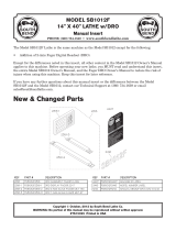
Centre turning attachment
Installing the centre turning attachment:
Note:
Longer work pieces are clamped between the brad points of
the main spindle and tailstock. The work piece must be
provided with a centre bore on both faces.
An exactly cylindrical work piece is only achieved if the points
align in the horizontal position.
1. Remove three fastening screws from the three-jaw chuck
and remove chuck.
2. Thoroughly clean the fit for the drive plate 3 (Fig. 20), the
centrepoint 1 and its fit in the main spindle.
3. Insert the centrepoint 1 in the fit of the main spindle. Insert
the second centrepoint in the tailstock.
4. Insert adapter 4 in the drive plate 3 and tighten the stud
lightly. Push both over the workpiece 5. Screw driver 2 into
the spindle flange.
5. Clamp the workpiece between the centrepoints. Push drive
plate 2 (Fig. 21) over the driver and fasten to the workpiece
using Allen key 1.
Important
When using a centre fixed to the tailstock, regular lubrication
of the centre and centre bore is necessary to prevent overhea-
ting due to friction.
Removing the centrepoint:
6. Guide a suitable aluminium or brass rod through the main
spindle from left to right.
7. Hold the centre and release by lightly tapping the rod.
4-jaw chuck with individually adjustable jaws
Note:
Round, oval, square and irregularly shaped work pieces can
be clamped as it is possible to adjust the jaws individually.
Centric or eccentric clamping is possible. Unlike the three-jaw
chuck, centring of the work piece must be performed
manually.

- 21 -
1. Detach the three-jaw chuck and attach the four-jaw chuck.
2. Open the four jaws, clean the contact faces and clamp the
work piece lightly according to visual estimation.
3. Move the support and turning tool onto the plane surface of
the work piece.
4. Turn the chuck by hand to establish symmetrical deviations.
5. Adjust by opening one of the jaws and re-set the opposite
jaw accordingly.
6. Tighten all four jaws evenly, alternating crosswise.
Important
In the normal clamping jaw position, only work pieces with an
edge length of max. 55 mm can be clamped. The maximum
length is 100 mm in the reverse position. Larger work pieces
are not securely held. Danger of accident.
4-jaw chuck (concentrically clamping)
Jaws not individually adjustable (automatic centring). Chuck Ø
100 mm. Max. clamping range 83 mm. Larger work pieces are
not securely held. Danger of accident.
Collet chuck attachment and collet chucks
Note:
The collet chuck unit is especially suitable for processing
round parts with great precision. The concentricity is consi-
derably greater than when working with a jaw chuck.
1. Remove three fastening screws from the three-jaw chuck
and remove chuck.
2. Thoroughly clean the fit for the collet chuck mount 2
(Fig. 22) and the fit in the main spindle 1.
3. Attach the collet chuck mount 2 using four fastening
screws 3.
Important
Always use the correct collet chuck to suit the work
piece. Chucks with an oversized diameter are destroyed.
4. Insert the collet chuck 6 and loosely attach the union nut 5.
Important
Never tighten the union nut when there is no work piece
inserted. Remove the pins 4 for tightening the union nut 5
immediately after tightening.
5. Insert the appropriate work piece in the collet chuck and
tighten the union nut 5 using the tool pins 4.
Fixed steady rest
The steady rest is particularly suitable for hollowing out long
work pieces with diameters up to 50 mm.
1. Release the fastening screw 4 (Fig. 23) and position retai-
ning plate 3 laterally.
2. Place the steady rest on the bed guide and set to the desi-
red position.
3. Swivel the retaining plate 3 parallel to the steady rest base
and tighten fastening screw 4.
4. Release all clamp screws 1 and drive the individual retai-
ning jaws 2 onto the workpiece.
Important
The jaws 2 must only touch the work piece and must not
clamp it. Otherwise there is a risk of the work piece
surface becoming scratched and the motor becoming
overloaded.
If the work piece is not round and smooth at the support
point, it must first be turned round. Lubricate the jaws and
work piece regularly when turning.
5. Check that the work piece is positioned in the steady rest
free of play and re-tighten clamp screws 1.
Travelling steady rest
Installation identical to the fixed steady rest, but this steady
rest is attached to the support (Fig. 24).
Faceplate with clamps
This is installed in place of the lathe chuck. Ideal for clamping
larger and asymmetrical workpieces. Ø 150 mm. 2 continuous
T-grooves. incl. clamps.
EC Declaration of Conformity
Name and address:
PROXXON S.A.
6-10, Härebierg
L-6868 Wecker
Product designation: PD 400
Article No.: 24400
In sole responsibility, we declare that this product conforms to
the following directives and normative documents:
EU EMC Directive 2004/108/EC
EU Machinery Directive 2006/42/EC
DIN EN 61029-1 / 01.2010
Dipl.-Ing. Jörg Wagner
PROXXON S.A.
Machine Safety Department
The CE document authorized agent is identical with the
signatory.
DIN EN 55014-1 / 05.2012
DIN EN 55014-2 / 11.2014
DIN EN 61000-3-2 / 03.2015
DIN EN 61000-3-3 / 03.2014
Date: 30.10.2015

- 102 -
19
14
22
16
15
17
18
18
20
21
1-13
16
15
17
20

Spare Parts List
Description :.rN-TE
hteet 02 ,leehwraeG10-00-00442
hteet 52 ,leehwraeG20-00-00442
hteet 03 ,leehwraeG30-00-00442
hteet 43 ,leehwraeG40-00-00442
hteet 53 ,leehwraeG50-00-00442
hteet 04 ,leehwraeG60-00-00442
hteet 54 ,leehwraeG70-00-00442
hteet 05 ,leehwraeG80-00-00442
hteet 55 ,leehwraeG90-00-00442
hteet 06 ,leehwraeG01-00-00442
hteet 56 ,leehwraeG11-00-00442
hteet 07 ,leehwraeG21-00-00442
hteet 57 ,leehwraeG31-00-00442
gnir etaidemretnI41-00-00442
pilC51-00-00442
sixA61-00-00442
eveelS71-00-00442
rehsaW81-00-00442
mra raeG91-00-00442
tun erauqS02-00-00442
wercS12-00-00442
tuN22-00-00442
- 103 -

- 104 -
2
76
102
1
4
5
5
16
19
5
5
93
92
61
69
70
72
74
73
75
50
51
49
48
45
10
10
10
10
4
11
12
94
17
18
9596 84
15
202122
22 21 20 25
26 27 28
29
30
38
39
40
41
36
31
33
34
35
8
6
7
6
7
24
23
3
42
43
86
85
87
52
53
117
114
113
116
115
118
112
56
47
88
50
66
62
62
66
71
1018182
57
5890
91
57
89
44
106
107
109
108
111
110

Spare Parts List
- 105 -

Description :.rN-TE
Spare Parts List
- 106 -

1
2
3
4 12
6
5
22
8
7
9
11
13
16
1920 21 17
2
15
14
10
Spare Parts List
- 107 -

- 108 -

Spare Parts List
- 109 -
/