Page is loading ...

6
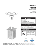
ASSEMBLY INSTRUCTIONS
2
3
2. Put the tabletop (E) throught the support, secure the
tabletop with 4pcs M6X12 bolts.
Hardware Used
BB
Bolt M6 x 12
x 4
Hardware Used
KK
Deck ring
x 1
E
1
1. Fix the support post (D) with 4pcs M6x30 bolts
and M6 flange nuts (AA).
Hardware Used
LL
Bolt M6 x 30
x 4
AA
M6 Flange nut
x 4
D
(LL)
I
J
KK
BB
3. Secure the wheel axes (J) on the side face of the
main frame with 4pcs M6X12 bolts(BB). Put the wheels
(I) through the axes, and then put 2pcs Φ8washers
(DD), firm the wheels with 2pcs M8 nuts (MM).
Put the deck ring (KK) through the post and above
the tabletop.
BB
Bolt M6 x 12
x 4
MM
M8 Nut
x 2
DD
Φ8 Washer
x 2
MM
DD

7
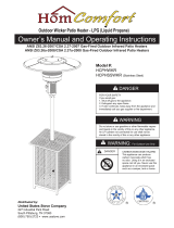
ASSEMBLY INSTRUCTIONS
4. Attach reflector spacers (CC) and three washers Ø8
(DD) to screen cover. Tighten the reflector spacers.
CC
DD
x 3
Reflector spacer
x 3
Washer Φ8
Hardware Used
Hardware Used
II
x 4
Stainless steel bolt M6 X 10
5. Attach head assembly to post.
5-1. Unscrew four stainless steel bolts M6 X 10 (II).
5-2. Load head assembly by inserting hose into post.
Insert head assembly into post.
Controlknobshouldbeabovedecalonpost.
Attach head assembly to post, and loosely install four
stainless steel bolts M6 X 10. Tighten bolts securely.
4
5-1
5-2
C
FF
GG

8
ASSEMBLY INSTRUCTIONS
Hardware Used
EE
FF
GG
6
7-1
TT
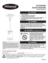
6. WARNING:Remove protective cover before
assembling.
Note: If necessary for proper alignment of reflector
sections, loosen each bolt prior to further assembly
and retighten after sections are aligned.
7. 7-1.Slide two reflector panels together.
Insert one
screw M6 X 10 (FF). Slide one washer ĭ 6
(EE) over threaded end of
screw M6 X 10 (FF) and
screw on cap nut (GG) loosely.
7-2. Slide reflector plate onto reflector panels.
Insert one
screw M6 X 10 (FF). Slide one washer ĭ 6
over threaded end of
screw M6 X 10 (FF) and screw on
cap nut (GG) loosely. Repeat procedure to complete
the assembly of all four sections. Fully tighten all of
the
screws in the rolled edge.
x 9
x 9
x 9
Washer ĭ 6
Screw M6 X 10
B
GG
EE
FF
A
Cap nuts
7-2
TT
GG
EE
FF

9
ASSEMBLY INSTRUCTIONS
Hardware Used
DD
HH
8 .Support heater. Slide three washers washer Φ8(DD)
over threaded end of spacer. Locate reflector assembly
on 3 spacers. Install three washers Φ8 on spacers and
securely tighten wing nuts (HH) but do not overtighten.
x 6
Washer Φ8
x 3
Wing nut
8
HH
DD
CC
DD
9
9. Screw gas hose and regulator (F) onto propane
cylinder (not included). Do not cross-thread.
WARNING: Use a standard 20 lb. propane cylinder
only.
Use this heater only with a propane vapor withdrawal
supply system. See chapter 5 of the standard for
storage and handling of liquefied petroleum gas,
ANS/NFPA 58. Your local library or fire department
should have this book.
A minimum supply pressure of 8” W.C. is required for
the purpose of input adjustment for propane gas.
Storage of an appliance indoors is permissible only if
the cylinder is disconnected and removed from the
appliance. A cylinder must be stored outdoors in a
well-ventilated area out of the reach of children. A
disconnected cylinder must have dust caps tightly
installed and must not be stored in a building, garage
or any other enclosed area. The minimum permissible
gas supply pressure of 8” W.C. is required for purpose
of input adjustment. A minimum of 17,000 BTUs per
hour is the required input rating for a heater with a
rating less than full.
The pressure regulator and hose assembly supplied
with the appliance must be used.
The installation must conform with local codes, or in the
absence of local codes,with national fuel gas code,
ANS Z223.1/NFPA54, natural gas and propane
Installation Code, CSA B149.1, or propane storage and
handling code, B149.2.
G
H

10
ASSEMBLY INSTRUCTIONS
WARNING: This product contains small batteries.
Swallowed small batteries can cause CHOCKING
HAZARD.Seek immediate medical attention if
batteries are swallowed or inhaled. Keep children
away from the small batteries.
Unscrew the switch button, load small battery, tighten
the switch button.
WARNING:
A dented, rusted or damaged propane cylinder may be
hazardous and should be checked by your propane
supplier. Never use a propane cylinder with a damaged
valve connection.
The propane cylinder must be constructed and marked
in accordance with the specifications for LP gas
cylinders of the U.S. Department of Transportation
(DOT) or the standard for cylinders, spheres and
tubes for transportation of dangerous goods and
commission, CAN/CSA-B339.
The cylinder must have a listed overfilling prevention
device.
The cylinder must have a connection device compatible with the connection for the appliance.
The cylinder used must include a collar to protect the cylinder valve.
Never connect an unregulated propane cylinder to the heater.
Do not store a spare LP-gas cylinder under or near this appliance.
Never fill the cylinder beyond 80 percent full.
Place the dust cap on the cylinder valve outlet whenever the cylinder is not
in use. Only install the type of dust cap on the cylinder valve that is provided with
the cylinder valve. Other type of caps or plugs may result in leakage of propane.
Standard 20 lb. tank
/