Page is loading ...

~~,
TURBO-HOUSETM AIR INLET
Installation and Operation Manual
MV938B12-993

TURBO-HOUSETM Air Inlet Manual
-;:>,
WARRANTYWFORMADON
Chore- TimeEquipment warrants each new product manufactured by it to be free from defects in
material or workmanship for one year from the date of initialinstallation by the original purchaser.
Ifsuch a defect is found by Chore-Time to exist within the one year period, Chore-Time will.at its
option, (a)repair or replace such product free of charge, F.O.B.the factory of manufacture, or (b)
refund to the original purchaser the original purchase price, in lieu of such repair or replacement.
Additional extended warranties are herewith provided to the original purchaser as follows:
1. RLXFans, less motors, for three years from date of installation.
*2. Poultryfeeder pans that become unusable withinfive years from date of instal-
lation. Warranty prorated after three years usage.
3. MEAL-TIME@Hog Feeder pans that become unusable within five years of instal-
lation.
4. Rotating centerless augers, excluding applications involvingHigh Moisture Corn
(exceeding 18%),for ten years from date of installation. Note: MULTIFLO@and
applications involving High Moisture Corn are subject to a one year warranty.
5. Chore-Time manufactured roll-formed steel auger tubes for ten years from date
of installation.
*6. Laying cages that become unusable within ten years. Warranty prorated after
three years usage.
7. ULTRAFLO@Auger and ULTRAFLO@Feed Trough (except ULTRAFLO@Trough Lin-
ers) are warranted for a period of five (5) years from date of original purchase
against repeated breakage of the auger or wear-through of the feed trough.
Conditions and limitations:
1. The product must be installed and operated in accordance with instructions
published by Chore-Time or warranty willbe void.
2. Warranty isvoid ifall components of a system are not supplied by Chore-Time.
3. Thisproduct must be purchased from and installed by an authorized Chore-Time
dealer or certified representative thereof. or the warranty willbe void.
4. Malfunctions or failure resulting from misuse, abuse, negligence, alteration, ac-
cident, or lack of proper maintenance shall not be considered defects under
this warranty.
5. Thiswarranty applies only to systems for the care of poultry and livestock. Other
applications in industry or commerce are not covered by this warranty.
Chore-Time shall not be liable for any consequential or special damage which any purchaser may
suffer or claim to have suffered as a result of any defect inthe product. 'Consequential' or 'special
damages' as used herein include, but are not limited to, lost or damaged products or goods, costs
of transportation, lost sales, lostorders, lost income, increased overhead, labor and incidental costs
and operational inefficiencies.
THISWARRANTY CONSTITUTES CHORE-TiME'S ENTIREAND SOLEWARRANTY AND CHORE-TIME EXPRESS-
LY DISCLAIMS ANY AND ALL OTHERWARRANTIES, INCLUDING, BUTNOT LIMITEDTO, EXPRESSAND IM-
PLIED WARRANTIES AS TO MERCHANTABILITY, FITNESS FOR PARTICULAR PURPOSE SOLD AND
DESCRIPTION OR QUALITY OF THEPRODUCT FURNISHEDHEREUNDER.
Any exceptions to thiswarranty must be authorized inwritingby an officer of the company. Chore-
Time reseNes the right to change models and specifications at any time without notice or obliga-
tion to improve previous models.
*See separate 'WARRANTYADDITION'as to these products
CHORE-TIME EQUIPMENT, A Division of CTB, Inc.
P,O, Box 2000,
Milford, Indiana 46542-2000 U.S,A,
PAGE2

~,
SAFETY INFORMATION
TURBO-HOUSETMAir Inlet Manual
CHORE-TIME is concerned about the safety of its customers. Caution. Waming and Danger Decals have been placed on the
equipment to warn of potentially dangerous situations. Care should be taken to keep this information intact and easy to read
at all times. Replace missing or damaged safety signs.
Safety-Alert Symbol
This is a safety-alert symbol. When you see this symbol on your equipment. be alert
to the potential for personal injury
.
Signal Words
Signalwords areused in conjunction with the safety-alert symbolto identify
the severity of the warning.
DANGER identifies immediate hazards which Wll.L
result in severe personal injury or death.
WARNING identifies hazards or unsafe practices which
COULD result in severe personal injury or
death.
CAUTION identifies hazards or unsafe practices which
COULD result in minor personal injury or
product or property damage.
DANGER--ROTATING PARTS
{lg
~@
This decal is placed on the Anti-Reverse Switch
Bracket of the Winch.
Severepersonal injury will result if the equipment is
operated withoutcovers properly installed.
2527 - I0
DANGER--ELECTRICAL HAZARD
Disconnect electrical power before inspecting or servicing equipment unless
maintenance instructions specifically state otherwise.
Ground all electrical equipment for safety.
All electrical wiring must be done by a qualified electrician in accordance with
local and national electric codes.
Ground all non-current carrying metal parts to guard against electrical shock.
PAGE3
A
A DANGER
AWARNING
A CAUTION
& [Q)~[f!J@~~
Rotating Partsl
Do not operate with
covers removed!
Disconnecl electrical power
before working on system.
equipment may start auto-
ma II co I I y. Olherw I se severe
personol injury wi (, resull.
."'1.32 31'!0
& DANGER
~
ELECTROCUTION
HAZARD
Do not open this con-
trol bo. until .I.ctrlcal
power Is di sconnecled
2527-251 I 01 eireUII breolers.
MA580. J4 12/89
~-

TURBO-HOUSE71ol Air Inlet Manual
.",
THANK-YOU
The employees of CHORE-TIME thank youfor your
recent purchase of the TURBO-HOUSE Air Inlet
System. We are certain the equipment you have
purchased, when properly installed, will provide
years of trouble free service. If a problem should
arise, your CHORE-TIMEdistributor can supplythe
necessary information to get your system operating
properly.
Please read the Safety Information on page 3 and
the installation instructions in this manual prior to
beginning the installation. This manual is designed
to give necessary information on the installation of
your TURBO-HOUSE Air Inlet System.
Please pay special attention to the electricalwiring
notes, they are there for ~ protection.
Important Note: When referring to
lumber in the installation section,
2 x 4 represent the industry standard
1-3/4" x 3-1/2" (45 x 90 mm) boards.
Introduction
~~mtMMtt@tmm::mmWMM~mm@mtt:wmw:m$1M~]lli1m~~im~
~~~~~~j
~~t
~t1
i:::~jj
:.:.:.:.:
1IIIIIIi
~Iiiii
IIII1
~:::~:
~~~~~:~
~m
~iiiiii
~tt
~::::::
:.:.:.:.
!~!~!~
~11
~~~~~
TOOLS NEEDED FOR INSTALLATION
Open End Wrenches (3/8", 7/16")
Side Cutters
Nut Driver (3/8", 7/16")
Standard Socket & Ratchet Set
Electric Drill and Bits
Tape Measure
Flathead Screwdriver
Level
Channel-LockPliers
Hammer
Cable Cutters
The Chore-Time TURBO-HOUSE Air Inlet is designed for use in confinement poultry buildings where the attic is used as an intake
plenum. The TURBO-HOUSE Air Inlet system allows fresh air to enter through the ceiling for better air quality and temperature
distribution .
The TOTAL area of ALLeave and/or ridge openings MUST be equal to or greater than the total area of the slots in the ceiling for the
TURBO-HOUSE Inlet. See your building plans or measure the existing dimensions to check this requirement.
UNDERSIZED VENTILATIONOPENINGS WILLRESTRICT AIRFLOW ANDWILLRESULT IN PRODUCTION LOSSES ANDIOR
MORTALITYLOSSES.
Installation
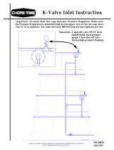
Chore- Time recommends insulation in BOTH the ceiling and the roof line of the attic for best year-round air system performance and
temperature distribution control. FIgure 1 shows a cross-section of the TURBO-HOUSE Air Inlet ceiling construction options for blown
insulation and rigid styrofoam board insulation.
IMPORTANT: Installation of a mounting board (2 x 4) must allow room to secure ramp hanger shown in FIgure 1 to the outside face
of the 2 x 4 (45 x 90 mm) board.
For best results, the ceiling slot length should be an even increment of 8 feet (2.43 m). The 2 x 4 (45 x 90 mm) mounting board should
extend an additional 2 feet (610 mm) beyond the ends of the slot to accommodate the last Hanger and Ramp assembly and to avoid
trimming 8 foot (2.43 m) parts (Inlet Curtain Assemblies and Side Rails). Therefore, the total length of the 2 x 4 (45 x 90 mm) mounting
board should be as follows:
Mounting Board Length = Slot Length +2 feet (610mm).
The additional two feet (610 mm) of inlet should extend beyond the cage row toward the end where the Inlet Power Unitwillbe located.
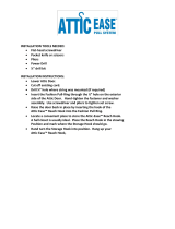
Ramp Hangers
Rgure 2 shows the location of the Ramp Hangers on the mounting board. The Ramp Hangers are paired in sets of two. The second
Ramp Hanger is placed every 21 1/4" (54 cm) behind the fIrSt.The next set of Hangers should be 96" (2.43 m) on center from the
previous set of Hangers.
Mounting and Assembly of Inlet Components
Begin the installation with the Ramp Hanger at the end of the slot nearest the system power unit (winch); The power unit may be located
on either end wall of the building, but the cables connecting the power unit to the inlet rows MUST NOT interfere with fillsystem tubes,
water pipes, or electrical conduits.
PAGE 4

TURBO-HOUSETM Air Inlet Manual
,;;"
Figure 1.
CEILING
WITH
BLOWNINSULATION
BLOWNINSULATION ~
~/////
///// /////// /// //
///// /////// /// //
/////////////// //
////////////// //
///////////// ///
//////////// ///
'/////////// ////
/////////// ////
/////////// /////
////////// /////
/////// /// ///////
////// /// ///////
.///// /// ////////
"<y/ / / / / / / / / / / / / / /
~ / 'u'-<---< ,: <- / ~
CCEILINGVAPORBARRIER "'><:: I f'" (152..)
(PLASTIC SHEET)
CONTINUOUS2" X +" MOUNTING BOARO
(FASTEN TO BOTTOMOF TRUSS COROS)-
RAMPHANGER
1/+" (6.35 om) PLYWOODBLOCKINGBOARD
(FOR BLOWNINSULATION)
(FASTEN BETWEENTRUSSES)
.5" (1+0..)
/ / / / / / / /~/ / / /' -
/////////////// /
////////////// //
////////////////
///////////// ///
///////////// ///
//////////// /// /
//////////// /// /
1
////////////////
////////////////
////////// /// ///'
////////// /// ///
///////////////
]
////////////////
///////////////
/ / / / / / / / ./ / / / / / / /
'"
CEILING SHEETMETAL
3/32 .'n.
(2.4..)
13/32.In.
(27.B..)
CLEARANCEREQUIRED
FOR MQUNT!NG
RAMPHANGER.
CEILING
WITH RIGID
INSULATION
,
RIGIO BOARD
INSULATI ON
2" X +" BOARO
(F ASTEN BETWEENTRUSSES)
'"
CEILING SHEETMETAL
3/32 .I ".
(2.1 ..)
I 3/32 .'n.
(27.8 .m)
CLEARANCEREQUIRED
FOR MQUNT!NG
RAMPHANGER.
HV938.1 9/93
(330 ..)
6"'SLOT OPENING
( I 52 m m )
3"'
(76 ..)
MV938.9 9/93
I
" %"
. ()m>-
~
(2.43.J
FOUR #10 X I MOUNTING..!
SCREWSPER HANGER USE HANGERTAB TO
HANGERVERTICALLY
Fi
g
ure2. ENDVIEW
(DETAIL)
RAMPHANGERS~II
I
~ 21.25"'
(S+D ..).
STARTING END
"(RAMPHANGERS
LOCATE
PAGE5

TURBO-HOUSErn Air Inlet Manual
~,
RAMP HANGER
MOUNTI NG BOARD
RAMPHANGER
RAMP
INSTALL RAMPSINSIDE HANGERS
WITHSTUDSOUTWARDTHROUGHSLOTS.
SECUREUSING
..10-24 NUTS.
Curtain Seal Assemblies
Ramps
Figure 3 shows the location of the
Ramps. The Ramps are mounted
insideof themounted Hangerswith the
3/8" hex head nuts. The nuts on the
Ramps should not be fully tightened to
allow for adjustment of ramps after the
entire Inlet is mounted and the power
unit is connected. For more
information, see section titled "FINAL
ADJUSTMENT"on page 10.
Refer to FIgures 4 through 7 when installing the Curtain Seal Assemblies.
Starting from one end, install (1) 29339-1 and (1) 29339-2 End Curtain Inlet Assembly, as shown in FIgure 5. The heat-sealed edge
of the end curtain must be toward to the starting end of the row to retain the curtain tubes used for weight.
Each End Curtain Assembly has either a male or a female end, as shown in Figure 6. These ends are used to overlap with the main
curtain (PIN 29280) to form a continuous
curtain inlet.To install, insert the male end inside the female opening so there is approximately
3" (76 mm) of overlap and 1/2" (12 mm) of gap between the two
curtain mounts, as shown in Figure 6.The 1/2"gap isrequiredto allow
for thermal expansion or contraction of adjacent parts. To control position and curtain length differences, always make sure the joining
location of the two curtain assemblies is approximately
centered within the distance between the two sets of hangers as shown in Figure
4.
Continueinstallingthe main curtain assemblies untilthe curtains have reached the last set of hangers. At this point, install (1) 29339-1
and (1) 29339-2 End Curtain Inlet Assembly to finish
each row, similar to the starting end.
Before installing Curtain Cap End Assemblies, measure the slot width between the 2x4 mounting board. This width should be
approximately 6" (152 mm) unless additional lumber was used to retain the attic insulation material. Install a wood block of this length
across the opening of the inlet at the front & back of the row. See Figure 7.
Secure one Curtain Cap End Assembly (PIN 29240) to each 2x4 block with (2) #10x1" screws. See Figures 5 & 7.
MOUNHNGBOARD\ I ~ 73. (J.85 N','. (2.'3 M). I
.~~-~~~~~~._~t::.~:):~
RAMPNANGER \ ",=Jf~
8' (2.43 MJ CURTAIN SEAL ASS'Y ~ EDGEOFENDCURTA[J
( PIN 29280 J INLETASSEMBLY
/ SEEDETAIL "8"
\
)
\../b/
SIX ..10 X I MOUNTINGSCREIIS
PER 8' CURTA[N SEAL ASS'Y, I
IMPORTANT, DO NOT OVER /
TIGHTEN SCREIIS. SCREWSSHOULD
ALLOII CURTA[N MOUNTTO EXPAND
DUE TO TEMPERATURECHANGE,
CURTAIN SEAL ASS'Y
Figure4.
PAGE6
DETAIL "8"

TURBO-HOUSETM Air Inlet Manual
~,
Figure 5.
HEATSEALEDEDGEOFCURTAIN~
CURTAIN CAP
END ASSEMBLY
(PIN
2924-0)
~
DETAIL "A"
ENDCURTAININLET ASSEMBLY
(PIN 29339-2)
CURTAIN INLET ASSEMBLY
(PIN 292BO)
MALEEND~
1\
)~
<?", ",~\..~
~ \.' \'1<(s~
c'vi'~
MV938.7 8/93
NV938.8 &/92
Detail A
~ FEMALEEND
Figure 6.
Figure7.
PAGE7

TURBO-HOUSETMAir Inlet Manual
.,,;,
Carriages And Side Rails
FIgure8 shows the placementof the
Carriages and the Side Rails, The Side
Rails willbe locked onto the Carriage by
closing the tabs. Use channel-lock pliers
through the large square holes in the
carriage fo bend tabs. These tabs should
be bent to limitmotionbetween the Side
Railsand the Carriage onthe firsttwoand
lasttwocarriages ineach row,
End Connectors
FIgure 8 shows the placement of the End
Connectors, An End Connector is
requi'ed at both ends of the Inletrowand
fastens to the end carriage withtwotabs,
two #10-24 x 3/8 flathead machine
screws, two #10-24 nuts, as shown in
Detail"A",
Side Rail Support
Position one Side Rail Support per 8'
(2.43 m) section in the mid-span of the
siclerail.
Deflector Boards
The styrofoamboard used inthe TURBO-
HOUSEInletmust be purchased (and cut
to width, if necessary) by the customer.
FIgure 9 gives the criticaldimensions for
the board. The boards may be added as
the row is built or after the whole row is
installed.
The board should be placed such that the
endsmeetabovethecarriages,
Chore-Time recommends 1" (25 mm)
thick styrofoam board with double-
sided aluminum foil bacldng.
Securing Deflector Boards
The styrofoam boards are to be secured to
the carriages with two Clips as shown in
FIgure 10. To install, puncture a hole
through the board using the 1/4" (6mm)
hole in the carriages as a guide. After
location of hole is made, press Clip down
through the styrofoam board and into the
carriage to fasten.
~~~
~~~=-- ~_.~ '::~~)
DETAIL'8' Side Roil S'pp,d DETAIL-A'
- DETAIL 'C' -
End Connedor
REFERTO THIS FIGURE
FORALL CARRIAGES
IIITHOUTENDCONNECTORS.
"...""~~ ".
~ ~Slde ROllI"-..
I . o' 1 .
Corrloge 1 1
Send Th... Tob.
DETAIL "8" to ncur.
- Roll. to Carriage.
REFERTOTHIS FIGURE
FORCARRIAGESAT EACH
ENDOF I NLETROil.
1)
Sid. Roll
"..."'" ~
.ppo rI Carr! oge
DETAIL 'C'
HV'338.3 9/93
Figure8.
NuI
I
I
%. (2.43 M)
1
t.
CUT HERE
.0
11.875 - .125
---------------------
~O2 ..f:L.)
CUT HERE
48" ( I .22 M)
---------------------
L
CUTHERE
---------------------
STYROFOAMBOARD
HVB8+.(, 9/'J3
Figure9.
End Connector
Figure 10.
PAGE8

~.\,
Power Unit Hook-Up
When properly installed, the TURBO-HOUSE Inlet requires
approximately 7 Ibs (3.17 kg) per 8 foot section of pull to close
the inlet completely against the seal. The power unit must match
the load requirements of the Inlet system. Two Chore-Time power
units are available for use with the TURBO-HOUSE Inlet: the Light
Duty Winch and the Heavy Duty Winch.
See Figure 11 for the recommended layout of the inlet and power
unit cable system.
Refertothisformulatodetenninethepropersizeofpowerunit.
System load = number of 8 foot sections X7 (Ibs required
to pull each section) .;. 2 (reduced load through turnback
pulley).
Example: System using (400) 8' sections.
400 X 7 .;.2 = 1,400 Ibs (635 kg) of pull
Power Unit Capacities
Light Duty Winch SOOIbs. (226 kg)
Heavy Duty Winch 2,000 Ibs. (907 kg)
Ifthe load requirement is less than SOOIbs (226 kg), the Ught Duty
Winch is adequate. For load requirements over 500 Ibs (226 kg),
use the Heavy Duty Winch. NOTE: For systems with over 6 rows of
inlets, multiple power units may be necessary to avoid clearance
problems with overhead doors, electrical panels, etc.
Mount the power unit high enough on the end wall so that the center
of the winch drum is even with the inlets. Ifthe inlet cable system
will be connected to both sides of the winch, the power unit should
be mounted as close to the center of the end wall as possible. If
possible, the load should be balanced on both sides of the winch.
Ifthe Heavy Duty Winch is required, use the cable supplied with the
winch to form the turnback loop, as shown in FIgure 11. The winch
drum should be out of cable when the inlets are completely open.
IMPORTANT: Do not pre-wrap the cable on the drum.
Mount the end pulleys on the end wall directly in line with the inlets.
40" (102 CM)
TURNBACK PULLEY
TURNBUCKLE
TO INLET
TOWER
SWITCH
Figure11.
TURBO-HOUSEru Air Inlet Manual
IMPORTANT:
Turn-back pulleys and row pulleys must align with each other and
the front of the power unitwinchdrum:
Inorder to align the pulleys with the winch drum, it may be
necessary to create a stand-off bracket for each pulley location.
Chore-Time does not supply these brackets.
Forapplications using the Heavy DutyWinch,the stand-off bracket
should be approximately 8" (20.3 cm).
For applications using the LightDutyWinch, the stand-off bracket
should be approximately 7" (17.8 cm).
Misalignmentwillcause additional pull force, pulley failure, and
system malfunction.
If(optional) hand winches are used to operate during power
outage, the hand winches ~ be returned to theiroriginal position
forthe power unit to operate properly.
Connect cable to Inlet End Connectors, turnbuckles, and to the
backsideofthe turnbackpulleyshown inFigures 11 and 12.
IMPORTANT:
USE THREEt CABLE CLAMPS ON ALL CABLE SPLICE
CONNECTIONSTO INSURETHATNO CABLE SUPPAGE WILL
OCCUR.
Tower Switch Installation
Tower Switch installationinstructions are supplied with the Tower
Switch.
Mountthe TowerSwitchso that the top of the tower is even withthe
inlets.TheTowerSwitchmaybe mounted ina comer ofthe buildingout
ofthe wayofbirdtransportbuggies,feed carts, etc.
ANCHORPOINT
\
TURNBACK PULLEY
USE THREE (3)
CLAMPSAT EACH
CABLE CONNECTION.
POWERUNIT
NOTE,CABLEONPOWERUNIT
DRUMIS T TO8"
( 18 TO20 CM)
AWAYFROMTHEWALL.
DEPENDINGONTHE
POWERUNIT USED.
TURNBUCKLE
TO INLET
MV884.7 8/93
PAGE9

TURBO-HOUSETM Air Inlet Manual
"",
~
~ 2 X 4 MOUNTING BOARD
/" (45 X 90 ..J
---
CONNECTTHE CABLE TO
THE FRONTOF THE END
CONNECTORAS SHOWN.
CABLE-
Figure12.
1.5"
(38..J
Figure13.
Final Adjustment
ROW ALIGNMENT: After the inlet rows are all connected to the power unit, adjust the tumbuckle(s) so that all of the inlet rows reach the fully open
position and the fully closed position at the same point. The following description defines the open and closed position of the carriage wheels on
the ramps.
FULLY OPEN: Carriage wheels resting against the Ramp Support Hanger. At this point the bottom limit switch on the Tower Switch(es) should
be activated.
FULLY CLOSED: The center of the carriage wheels are 1.5 inches (38 mm) from the edge of the Ramp Hanger, as shown in Figure 13. At this
point the top limit switch on the Tower Limit Switch should be activated.
RAMP
ADJUSTMENT: Use the winch to pull the system up until the carriage wheels are in the 'closed' position on the ramps. The ramps should
be adjusted so that the seals just touch the deflector boards all along the inlet row.
Controlling the Inlets
The TURBO-HOUSE Inlets may be controlled by the Chore-Time Automatic Static Pressure Inlet Control. The pressure setting on the Inlet Control
should be set to operate at 0.05" static pressure. The pressure sensor bottle(s) for the Inlet Control should be located so that the control senses
the pressure drop across the inlet ONLY. The bottle(s) should be located in the bird area and the attic area (inside the building) to measure the
required pressure drop.
Note: The fans
Yti!.I operate at a higher static pressure that the Inlet Control willread. The Inlet Control must measure the pressure differential across
the inlet ONLY.
Wirethe system accordingto the wiringdiagrams inthe Controlinstructionsand the Heavyor LightDutyWinchInstructions.

~~,
TURBO-HOUSETM Air Inlet Manual
TURBO-HOUSE Air Inlet Components
Imm
1*
2**
3**
4**
5*
6*
7*
8*
9*
10**
11**
12*
13**
14*
15
16*
17
18**
19*
Description
Curtain Inlet Assembly
Inlet End Curtain Assembly (L.H.)
Curtain Cap End Assembly
Inlet End Curtain Assembly (R.H.)
1/2" PVC Curtain Weight
Ramp Hanger
Clip
Side Rail Support
Carriage Assembly
Carriage
Nylon Sheave
#10-24 x 3/8 Countersunk Screw
End Connector
#10-24 Nut
Single Pulley Assembly
Side Rail
Pulley Assembly
Ramp (Studs to left)
3/16" 7 x 19 Aircraft Cable
Turnbuckle
Ramp (Studs to right)
cv
9
i!
y
Part No.
29280
29339-1
29240
29339-2
28672-29
28789
28671
30122
30125
30124
2452
8636-2
28791
27795
27301
30123
2500
27069-1
13976
27389
27069-2
T-~
~?
,
ORDERING INFORMATION
1. All parts should be ordered by PART NUM-
BER and DESCRIPTIONasgiven in the
PARTS LIST.
2 Partsare alwaysbilledwhenshipped. If a re-
turned part is defective, and within warranty
period,credit will be allowedagainst billing.
3. CHECK SHIPMENT FOR DAMAGESAND
SHORTAGES.
4. Allclaimsfordamages orshortagesresulting
from shipment must be filedwith the carrier.
*These items may be ordered as an assembly under part
no. 30152.
**These items may be ordered as an assembly under part
no.29481
PAGE11

TUIgJ.,O-HOUSETMAir Inlet Manual
CHDRE-TIME
@
Made to work.
Built to last.
/