Page is loading ...

INSTALLATION &
OPERATION MANUAL
BCD615R Series
Battery Charger
8128 River Way, Delta B.C. V4G 1K5 Canada T. 604.946.9981 F. 604.946.9983 TF. 800.668.3884 (US/CANADA)
www.analyticsystems.com
An ISO9001 and AS9100 Registered Company Battery Chargers • Inverters • Power Supplies • Voltage Converters

Copyright (2005-2014) Analytic Systems Ware (1993) Ltd.

3
IMPORTANT & SAFETY INSTRUCTIONS
1. SAVE THESE INSTRUCTIONS — This manual contains important safety and operating
instructions for the battery charger.
2. CAUTION — To reduce risk of injury, charge only lead acid or sealed gel cell type
rechargeable batteries. Other types of batteries may burst causing personal injury and
damage.
3. Do not expose battery charger to rain or snow.
4. Use of an attachment not recommended or sold by the battery charger manufacturer may
result in a risk of re, electric shock, or injury to persons.
5. Do not disassemble battery charger; take it to a qualied serviceman when service or
repair is required. Incorrect reassembly may result in a risk of electric shock or re.
6. To reduce risk of electric shock, disconnect battery charger from batteries or other DC
supply before attempting any maintenance or cleaning. Turning off controls will not
reduce this risk.
7. Never allow battery acid to drip on battery charger when reading gravity or lling battery.
8. O/P CONNECTION PRECAUTIONS
Connect and disconnect DC output connections only after setting I/P power switch to the
off position.
GENERAL WARNING
1. WARNING — RISK OF EXPLOSIVE GASES.
i. WORKING IN VICINITY OF A LEAD-ACID BATTERY IS DANGEROUS. BATTERIES
GENERATE EXPLOSIVE GASES DURING NORMAL BATTERY OPERATION. FOR THIS
REASON, IT IS OF UTMOST IMPORTANCE THAT EACH TIME BEFORE SERVICING
EQUIPMENT IN THE VICINITY OF THE BATTERY, YOU READ THIS MANUAL AND FOL-
LOW THE INSTRUCTIONS EXACTLY.
ii. To reduce risk of battery explosion, follow these instructions and those published by
battery manufacturer and manufacturer of any equipment you intend to use in vicin-
ity of battery. Review cautionary marking on these products and on engine.
2. PERSONAL PRECAUTIONS
i. Someone should be within range of your voice or close enough to come to your aid
when you work near a lead-acid battery.
ii. Have plenty of fresh water and soap nearby in case battery acid contacts skin, cloth-
ing, or eyes.
iii. Wear complete eye protection and clothing protection. Avoid touching eyes while
working near battery.
iv. If battery acid contacts skin or clothing, wash immediately with soap and water.

4
If acid enters eye, immediately ood eye with running cold water for at least 10
minutes and get medical attention immediately.
v. NEVER smoke or allow a spark or ame in vicinity of battery or engine.
vi. Be extra cautious to reduce risk of dropping a metal tool onto battery. It might spark
or short-circuit battery or other electrical part that may cause explosion.
vii. Remove personal metal items such as rings, bracelets, necklaces, and watches when
working with a lead-acid battery. A lead-acid battery can produce a short-circuit cur-
rent high enough to weld a ring or the like to metal, causing a severe burn.
viii. NEVER charge a frozen battery.
ix. If necessary to remove battery from service, always remove grounded terminal from
battery rst. Make sure all accessories in the vessels are off, so as not to cause an
arc.
x. Be sure area around battery is well ventilated.
xi. Clean battery terminals. Be careful to keep corrosion from coming in contact with
eyes.
xii. Study all battery manufacturer’s specic precautions such as removing or not remov-
ing cell caps while charging and recommended rates of charge.
xiii. Add distilled water in each cell until battery acid reaches level specied by battery
manufacturer. This helps purge excessive gas from cells. Do not overll. For a battery
without cell caps, carefully follow manufacturer’s recharging instructions.
3. BATTERY CHARGER LOCATION
i. Never place battery charger directly above battery; gases from battery will corrode
and damage battery charger.
ii. Never allow battery acid to drip on battery charger when reading gravity or lling
battery.
Analytic Systems does not recommend the use of the BCD615R Series DC Battery Chargers
in life support applications where failure or malfunction of this product can be reasonably
expected to cause failure of the life support device or to signicantly affect its safety or
effectiveness. Analytic Systems does not recommend the use of any of its products in direct
patient care.
Examples of devices considered to be life support devices are neonatal oxygen analyzers,
nerve stimulators (whether used for anesthesia, pain relief, or other purposes), autotransfu-
sion devices, blood pumps, debrillators, arrhythmia detectors and alarms, pacemakers,
hemodialysis systems, peritoneal dialysis systems, neonatal ventilator incubators, ventilators
for both adults and infants, anesthesia ventilators, and infusion pumps as well as any other
devices designated as “critical” by the U.S. FDA.

5
Introduction
All new Current Mode switching design offers increased power and reliability in a compact
package. Extra input and output ltering reduce EMI to extremely low levels. Reliability
features include an input fuse, thermal shutdown, current limiting, reverse battery hookup
protection and output short circuit shutdown with automatic recovery. The output voltage is
easily adjusted 1.0 volts above or below the standard output voltage. The model BCD615R
Battery Charger supplies either 12, 24, 32 or 48 VDC from a 110, 250 or 300 VDC power
source. High quality digital meters can be added (factory option) to allow monitoring of charg-
ing current and charging voltage.
Specications
Input Voltages
Nominal (ip) 24 48 72
Actual 20-35 40-60 65-90
Input Amps (max) 37.9 19.4 12.1
Input Fuse (ATC) 15 x 3 25 x 1 25 x 1
Output Voltages
Nominal (op) 12 24 48
Output Volts (DC) 13.6 ± 0.05 27.2 ± 0.05 54.4 ± 0.05
Absorption Voltage (Vdc) 14.4 28.8 57.6
Charging Amps 40 20 10
Absorption to Float 6.0 Amps 3.0 Amps 1.5 Amps
Battery Size (Amp Hour)* 160 – 240 80 – 132 40 - 60
Output Fuse (ATC) 40 x 2 30 x 2 15 x 2
Battery Banks 1 or 2 (3 available) 1 or 2 (3 available) 1 or 2 (3 available)
Output Adjustment (Vdc) ± 1.0 Volts
Output Crowbar 16.0 ± 0.5 V 32.0 ± 1.0 V 63.9 ± 2.0 V
Temperature Compensation Coefcient -30mV / o C -60mV / o C -120mV / o C
Effeciency >75% @ maximum output
Environmental Specications
Operating Temp. Range
-25° to +40°C @ maximum output
Derate Linearly 2.5% per °C from 40°C
(Optional -40°C extra wide temp. operation avail.)
Humidity
0 - 95% Relative Humidity
(non-condensing) with optional conformal coating
Audible Noise NONE Ødb @ 3ft (34.5 dB when fan operating)
Typical Service Life > 10 yrs. (87,600 hrs)
Isolation
Input-Case & Input-Output 1500 Vdc (500V @ 24V I/P)
Output-Case 500 Vdc @ 48V O/P)

6
* Specications subjects to change without notice.
Installation
MOUNTING
Mount the unit in a DRY location. Allow at least 4 inches of clearance around the heat sink
ns for adequate cooling. .
POWER CONNECTION
The unit is supplied with power leads about 3 feet long. This should normally be adequate to
connect to a source of power. If you must extend the power leads, be sure to use at least a
good quality (typeTEW) AWG 8 gauge wire. The wire colours are:
All connections should be made inside an appropriate junction box. Refer to the specications
table for the correct sizing of the circuit breaker in the distribution panel.
If the power is connected in reverse, the input fuses will blow. Remove the top cover of the
charger to replace them.
Red - Positive Black- Negative
Mechanical Specications
Depth 13.5 in / 34.3 cm
Width 19.0 in / 48.3 cm
Height 3.5 in / 8.9 cm
Clearance 1 inch (2.5 cm) all around
Material Marine Grade Aluminium
Finish Black Anodize / Powder Epoxy Coat
Fastenings All 18.8 Stainless Steel
Weight 7.6 lb / 3.3 Kg
Connections Four contact output terminals
Warranty 3 years
Designed and manufactured by: ANALYTIC SYSTEMS WARE (1993) LTD.
8128 River Way
Delta, BC V4G 1K5 Canada
p. 604.946.9981 f. 604.946.9983
tf. 800.668.3884 US/Canada

7
Operation
Turn the switch on the front panel of the unit on to energize the outputs. The green ‘Power
On’ indicator light will glow to indicate the proper operation of the unit. The Digital Meter
will show the voltage and current on either output 1 or output 2. Flip the toggle switch to
view the voltage and current on the other output. If the battery is connected in parallel, then
you will have to add the currents on each output to see the total charging current.
OUTPUT CONNECTIONS
Two Positive output terminals and two Negative output terminals are provided. Connect only
one wire to each terminal. Ensure that the total average load connected does not exceed the
continuous current rating of the unit.
To ensure spark free connections the power switch must be in the OFF position prior to making
the connections to the battery bank(s).
The charger may be hooked to 1 or 2 battery banks. Hook up the battery bank(s) as shown
below. If you are hooking up 2 battery banks keep in mind that they MUST share a common
ground! If you are going to hook up one battery bank to the charger, you may hook up the
outputs in parallel to reduce stress on the output isolation diodes inside the charger.
OUTPUT 1 OUTPUT 1
OUTPUT 2 OUTPUT 2
BATTERY
BANK #1
BATTERY
BANK #1
BATTERY
BANK #2
BATTERY TEMPERATURE SENSORS
Up to 2 battery temperature sensors can be connected to the charger to allow temperature
compensation of the battery charging voltage (1 is supplied with the unit). If only the 1
sensor is used, it MUST be plugged into the ‘BATTERY 1’ connection on the rear of the unit.
If no sensor is used, the charger will default to standard output voltage.
The battery temperature sensor(s) must be physically attached to the battery bank(s) so that
it(they) can sense the temperature of the battery bank(s).

8
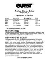
This charger features user selectable 2 or 3 stage charging. The charging prole is selected by
moving the slide switch on the front panel left to 3 stage or right for 2 stage charging.
A two-stage charger provides a constant current until the battery reaches its rated capacity
and then switches to a “oat” voltage. The current then reduces as necessary to maintain
the battery at the oat voltage. The charger can be connected to the battery indenitely and
will provide the appropriate prole. A two-stage charger is recommended in most instances
since it is the most versatile and can be permanently connected to attenuate the characteristic
discharge of unused batteries. A load can be put on the battery or batteries without altering
its ability to keep the battery at optimal charge.
100%
75%
50%
25%
0%
Bulk
(Constant Current)
Float
(Constant Volts)
Time
Two Stage Charge
Volts
Amps
100%
75%
50%
25%
0%
Bulk
(Constant Current)
Absorption
(Constant Volts)
Float
(Constant Volts)
Time
Three Stage Charge
Volts
Amps
2 or 3 Stage Charging
OUTPUT ADJUSTMENT
The unit has an adjustment potentiometer to allow up to ± 1.0V adjustment of the output
voltage. This potentiometer is accessed through a small hole in the front panel of the Battery
Charger. As shipped from the factory, the unit is preset for a voltage of 13.6, 27.2, 36.3 or
54.4VDC. If you wish to adjust this voltage, rst locate the output adjustment potentiometer
access hole next to the diagnostic LED’s on the front panel. Reach in with a very small at
blade screwdriver to rotate the potentiometer. Clockwise increases the output voltage and
counter clockwise decreases it. When you are done, replace the cover plate and securely
tighten the screws.

9
A three-stage charger is the fastest charger. It charges the battery at a constant current
until the battery voltage reaches a slightly elevated level. The battery is maintained at
this voltage while the charging current diminishes to a low value, and then the battery is
switched to the oat voltage where it can be maintained indenitely. However, the charger
cannot differentiate between a current going to a load on the battery, or being absorbed by
the battery, so it can overcharge a battery supplying current to a load. A two-stage charger
is preferred for “loaded” batteries and a three-stage for idle or unloaded batteries during
recharging.
All of Analytic Systems’ chargers include adjustable output voltage for charging standard or
deep cycle lead-acid, VLRA or gel type batteries.
The charger includes a user selectable equalize function. The purpose of the equalize func-
tion is to deliberately overcharge the battery to force any weak cells to recharge properly.
This function is required by most battery banks once every 2-3 months.
To start an equalize cycle, simply press the equalize button using a pencil or pen. If the
unit is charging (i.e. Charge light is ON), the equalize light will blink until the charging is
complete. The Equalize LED will come on solid when the equalize cycle starts. The equalize
cycle feeds a low current (typically 10 percent of maximum charging current) to a maximum
voltage as shown on the specications. This cycle runs for 3 hours and then the charger
resumes normal operation. If a shorter time is required, it can be programmed using the DIP
switches on the small equalize circuit board inside the charger.
Equalize
Equalize Time Control

10
Special Services & Options
Conformal Coating INCLUDED ON ALL UNITS UNLESS REQUESTED NOT TO as of April 1, 2014
Option “c” Ruggedization Package (EXTRA Conformal Coating and RTV Compound)
Option “v” Marine / Industrial Pkg (EXTRA Conformal dipping and RTV Compound)
Option “MS” Military Pkg
(incl. Wide Temp Components, Conformal Dipping and RTV Compound)
Option “w” Wide Temperature Operation (-40 to +55 C, incl)
Option “SM” High Voltage Protection on the DC Input Side
Option “d” Paralleling Diodes
Option “FI” Forklift Modi cations
Option “F” Open Frame - No chassis just heat sink bars (not for all products)
Special Input
There is no charge for nominal output voltages (ie. 12.0, 24.0, 48.0), but this
must be noted at the time of order (Contact Factory for details)
Special Output
Water tight options IP66, IPS67, IPS68
Troubleshooting
This unit provides LED indicators and a buzzer to help diagnose any problems. The unit should
sound the buzzer to alert you prior to shutting itself down. You should immediately check the
indicators to determine the cause of the shutdown.
CHARGING Indicates that the battery charger is charging the batteries:
If the LED is not on, the batteries may be fully charged and the charger is
supplying a oat voltage to the batteries to keep them fully charged.
LOW OUTPUT Indicates that the output voltage is below normal because:
The current demanded by the devices connected to the unit exceeds the
maximum output current rating, causing the output voltage to drop to
maintain the current at the maximum level,
The input voltage is not high enough for unit to operate,
LOW INPUT Indicates that the input voltage is below normal because:
The input voltage is not in the correct range for proper operation of the unit.
OVERTEMP Indicates that the Battery Charger is running too hot because:
Too much power is being drawn, turn off or unplug some devices.
The Battery Charger is located in a poorly ventilated area.
If the load exceeds the continuous rating for too long a period, the temperature sensor inside
the unit will turn off the outputs. After the unit cools sufciently, it will automatically come
back on. If this happens frequently, remount the unit for increased airow so it cools better.

11
Limited Warranty
1. The equipment manufactured by Analytic Systems Ware (1993) Ltd. (the “Warrantor”) is warranted to be free
from defects in workmanship and materials under normal use and service.
2. This warranty is in effect for:
a. 3 Years from date of purchase by the end user for standard products offered in our catalog.
b. 2 Years from date of manufacture for non-standard or OEM products
c. 1 Year from date of manufacture for encapsulated products.
3. Analytic Systems will determine eligibility for warranty from the date of purchase shown on the warranty card
when returned within 30 days, or
a. The date of shipment by Analytic Systems, or
b. The date of manufacture coded in the serial number, or
c. From a copy of the original purchase receipt showing the date of purchase by the user.
4. In case any part of the equipment proves to be defective, the Purchaser should do the following:
a. Prepare a written statement of the nature of the defect to the best of the Purchasers knowledge, and
include the date of purchase, the place of purchase, and the Purchasers name, address and telephone
number.
b. Call Analytic Systems at 800-668-3884 or 604-946-9981 and request a return material authorization
number (RMA).
c. Return the defective part or unit along with the statement at the Purchasers expense to the Warrantor;
Analytic Systems Ware (1993) Ltd., 8128 River Way, Delta, B.C., V4G 1K5, Canada.
5. If upon the Warrantor’s examination the defect proves to be the result of defective material or workmanship,
the equipment will be repaired or replaced at the Warrantor’s option without charge, and returned to the
Purchaser at the Warrantor’s expense by the most economical means. Requests for a different method of return
or special handling will incur additional charges and are the responsibility of the Purchaser.
6. Analytic Systems reserves the right to void the warranty if:
a. Labels, identication marks or serial numbers are removed or altered in any way.
b. Our invoice is unpaid.
c. The defect is the result of misuse, neglect, improper installation, environmental conditions, non-autho-
rized repair, alteration or accident.
7. No refund of the purchase price will be granted to the Purchaser, unless the Warrantor is unable to remedy the
defect after having a reasonable number of opportunities to do so.
8. Only the Warrantor shall perform warranty service. Any attempt to remedy the defect by anyone else shall
render this warranty void.
9. There shall be no warranty for defects or damages caused by faulty installation or hook-up, abuse or misuse of
the equipment including exposure to excessive heat, salt or fresh water spray, or water immersion except for
equipment specically stated to be waterproof.
10. No other express warranty is hereby given and there are no warranties that extend beyond those described
herein. This warranty is expressly in lieu of any other expressed or implied warranties, including any implied
warranty of merchantability, tness for the ordinary purposes for which such goods are used, or tness for a
particular purpose, or any other obligations on the part of the Warrantor or its employees and representatives.
11. There shall be no responsibility or liability whatsoever on the part of the Warrantor or its employees and rep-
resentatives for injury to any person or persons, or damage to property, or loss of income or prot, or any other
consequential or resulting damage which may be claimed to have been incurred through the use or sale of the
equipment, including any possible failure of malfunction of the equipment, or part thereof.
12. The Warrantor assumes no liability for incidental or consequential damages of any kind

8128 River Way, Delta B.C. V4G 1K5 Canada T. 604.946.9981 F. 604.946.9983 TF. 800.668.3884 (US/CANADA)
www.analyticsystems.com
An ISO9001 and AS9100 Registered Company Battery Chargers • Inverters • Power Supplies • Voltage Converters
/