VOLTCRAFT PL-135 HAN Operating Instructions Manual
- Type
- Operating Instructions Manual

PL-135 HAN HITZDRAHT-ANEMOMETER
BEDIENUNGSANLEITUNG
Seite 3 – 20
PL-135 HAN HOT-WIRE ANEMOMETER
OPERATING INSTRUCTIONS
Page 21 – 38
PL-135 HAN ANÉMOMÈTRE À FIL CHAUD
MODE D’EMPLOI
Page 39 – 56
PL-135 HAN HITTEDRAAD-ANEMOMETER
GEBRUIKSAANWIJZING
Pagina 57 – 74
Best.-Nr. / Item No. / N° de commande / Bestnr.:
283971
Version 08/14

2
Diese Bedienungsanleitung gehört zu diesem Produkt. Sie enthält wichtige
Hinweise zur Inbetriebnahme und Handhabung. Achten Sie hierauf, auch
wenn Sie dieses Produkt an Dritte weitergeben.
Heben Sie deshalb diese Bedienungsanleitung zum Nachlesen auf! Eine
Auistung der Inhalte nden Sie in dem Inhaltsverzeichnis mit Angabe der
entsprechenden Seitenzahlen auf Seite 3.
These Operating Instructions accompany this product. They contain
important information on setting up and using the device. You should refer
to these instructions, even if you are buying this product for someone else.
Please retain these Operating Instructions for future use! A list of the contents
can be found in the Table of contents, with the corresponding page number,
on page 21.
Le présent mode d’emploi fait partie intégrante du produit. Il comporte
des directives importantes pour la mise en service et la manipulation de
l’appareil. Tenir compte de ces remarques, même en cas de transfert du
produit à un tiers.
Conserver ce mode d’emploi an de pouvoir le consulter à tout moment. La
table des matières avec indication des pages correspondantes se trouve à
la page 39.
Deze gebruiksaanwijzing hoort bij dit product. Zij bevat belangrijke informatie
over de inbedrijfstelling en het gebruik. Let hierop, ook wanneer u dit product
aan derden overhandigt.
Bewaar daarom deze gebruiksaanwijzing om in voorkomende gevallen te
kunnen raadplegen. In de inhoudsopgave op pagina 57 vindt u een lijst met
inhoudspunten met vermelding van het bijbehorende.
Page is loading ...
Page is loading ...
Page is loading ...
Page is loading ...
Page is loading ...
Page is loading ...
Page is loading ...
Page is loading ...
Page is loading ...
Page is loading ...
Page is loading ...
Page is loading ...
Page is loading ...
Page is loading ...
Page is loading ...
Page is loading ...
Page is loading ...
Page is loading ...

21
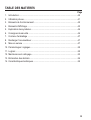
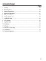
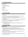
TABLE OF CONTENTS
Page
1. Introduction...........................................................................................................22
2. Intended use.........................................................................................................23
3. Operating elements ..............................................................................................24
4. Display elements ..................................................................................................25
5. Safety instructions ................................................................................................26
6. Delivery content ...................................................................................................29
7. Charging the rechargeable battery .......................................................................29
8. Operation..............................................................................................................29
9. Settings ................................................................................................................32
10. Software ...............................................................................................................34
11. Maintenance and cleaning ...................................................................................35
12. Disposal................................................................................................................36
13. Technical data ......................................................................................................37

22
1. INTRODUCTION
Dear Customer,
In purchasing this Voltcraft
®
product, you have made a very good decision for which we
would like to thank you.
Voltcraft
®
- In the eld of measuring, charging and network technology, this name stands
for high-quality products which perform superbly and which are created by experts
whose concern is continuous innovation.
From the ambitious hobby electronics enthusiast to the professional user, products from
the Voltcraft
®
brand family provide the optimum solution even for the most demanding
tasks. And the remarkable feature is: we offer you the mature technology and reliable
quality of our Voltcraft
®
products at an almost unbeatable price-performance ratio.
In this way, we aim to establish a long, fruitful and successful co-operation with our
customers.
We wish you a great deal of enjoyment with your new Voltcraft
®
product!
All company names and product names are trademarks of their respective
owners. All rights reserved.

23
2. INTENDED USE
Use this product to measure air temperature, airow velocity and volume ow rate via
an external, tethered telescopic hot-wire sensor with thermistor. The product is suited
for all kinds of applications related to heating, air-conditioning and ventilation. The
readings are shown on the LC display. When the product is connected to a computer,
the readings can be displayed as a graph and exported as a text document using the
included software. Power is supplied via an integrated LiPo rechargeable battery.
It is intended for indoor use only. Do not use it outdoors. Contact with moisture, e.g. in
bathrooms, must be avoided under all circumstances.
For safety and approval purposes (CE), you must not rebuild and/or modify this product.
If you use the product for purposes other than those described above, the product may
be damaged. In addition, improper use can cause hazards such as short circuiting, re,
electric shock etc. Read the instructions carefully and keep them. Make this product
available to third parties only together with its operating instructions.
This product complies with the statutory national and European requirements.
Observe all safety instructions and information within this operating
manual.
Page is loading ...

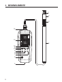
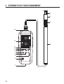
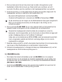
25
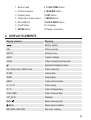
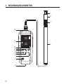
1 Sensor head
2 Protective sleeve
3 Gripping area
4 Telescopic hot-wire sensor
5 Mini-USB port
6 On/off button
7 ENTER button
8 FLOW TEMP button
9 MAX MIN button
10 SET button
11 MEAN button
12 HOLD ZERO button
13 LC display
14 Sensor connection
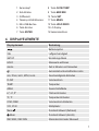
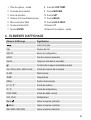
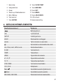
4. DISPLAY ELEMENTS
Display element Meaning
Battery symbol
VEL Airow velocity
SETUP Settings menu
HOLD Freeze readings
mm/ss Time in minutes and seconds
Automatic shutdown active
m/s, ft/min, km/h, MPH, knots Units of velocity
FLOW Volume ow
TEMP Temperature
AREA Cross sectional area
in
2
, m
2
, ft
2
Units of area
ºC, ºF Units of temperature
CFM, CMM Units of volume ow
X10, X100 Multiplier
Mean
Mean value (period)
Mean
Mean value (number)
REC MAX, REC MIN Max./min. reading

26
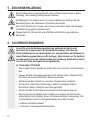
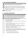
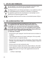
5. SYMBOL EXPLANATION
An exclamation mark in a triangle indicates important notes in these operating
instructions that must be strictly observed.
The triangle containing a lightning symbol warns against danger of electric
shock or impairment of the electrical safety of the device.
The arrow symbol alerts the user to the presence of important tips and notes
on using the device.
This device is CE compliant and fullls all applicable European guidelines.
6. SAFETY INSTRUCTIONS
Read the operating instructions carefully and especially observe the
safety information. If you do not follow the safety instructions and
information on proper handling in this manual, we assume no liability
for any resulting personal injury or damage to property. Such cases will
invalidate the warranty/guarantee.
a) Persons / Product
• The device is not a toy. Keep it out of the reach of children and pets.
• Do not leave packaging material lying around carelessly. These may
become dangerous playing material for children.
• Protect the product from extreme temperatures, direct sunlight, strong jolts,
high humidity, moisture, ammable gases, vapours and solvents.
• Do not place the product under any mechanical stress. If it is no longer
possible to operate the product safely, take it out of operation and protect
it from any accidental use. Safe operation can no longer be guaranteed if
the product:
- is visibly damaged,
- is no longer working properly,
- has been stored for extended periods in poor ambient conditions or
- has been subjected to any serious transport-related stresses.

27
• Please handle the product carefully. Jolts, impacts or a fall even from a low
height can damage the product.
• Also observe the safety and operating instructions of any other devices
which are connected to the product.
• Make sure the cables do not get crimped, bent or damaged by sharp
edges.
• Never use the product immediately after it has been brought from a cold
room into a warm one. The condensation generated could destroy the
product. Allow the device to reach room temperature before connecting
and using it. This may take several hours.
• In schools, educational establishments, hobby and self-help workshops,
the operation of this product must be monitored by trained personnel.
• For installations in industrial facilities, follow the accident prevention
regulations for electrical systems and equipment of the government safety
organization or the corresponding authority for your country.
• Connect the appliance to a wall socket that can be accessed easily.
• Only connect the power adaptor to a normal mains socket connected to
the public supply. Before plugging in the power adaptor, check whether
the voltage stated on the power adaptor complies with the voltage of your
electricity supplier.
• Never connect or disconnect power adaptors if your hands are wet.
• Never unplug the power adaptor from the mains socket by pulling on the
cable; always use the grips on the plug.
• Always lay the cables so that nobody can trip over or become entangled in
them. This poses a risk of injury.
• For safety reasons, disconnect the power adaptor from the mains socket
during storms.

28
b) Rechargeable batteries
• The rechargeable battery is permanently built into the product and cannot
be replaced.
• Never damage the rechargeable battery. Damaging the casing of
the rechargeable battery might cause an explosion or a re! Unlike
conventional batteries/rechargeable batteries (e.g. AA or AAA type), the
casing of the LiPo rechargeable battery does not consist of a thin sheet but
rather a sensitive plastic lm only.
• Never short-circuit the contacts of the rechargeable battery. Do not throw
the battery or the product into re. There is a danger of re and explosion!
• Charge the rechargeable battery regularly, even if you do are not using the
product. Due to the rechargeable battery technology being used, you do
not need to discharge the rechargeable battery rst.
• Never charge the rechargeable battery of the product unattended.
• When charging, place the product on a surface that is not heat-sensitive. It
is normal that a certain amount of heat is generated during charging.
c) Miscellaneous
• Consult an expert when in doubt about operation, safety or connection of
the device.
• Maintenance, modications and repairs are to be performed exclusively by
an expert or at a qualied shop.
Should you have questions concerning correct product connection or operation, or
should other questions arise that this user manual does not address, please do not
hesitate to contact our technical support or a third-party professional.

29
7. DELIVERY CONTENT
• Meter
• USB power adapter
• Telescopic hot-wire sensor
• USB cable
• Software CD
• Case
• Operating instructions
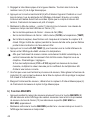
8. CHARGING THE RECHARGEABLE BATTERY
1. Connect the USB cable's Mini-USB plug to the Mini-USB port (5) on the meter.
2. Connect the USB cable's USB A plug to a USB port of a USB power source (i.e.
computer, USB power adaptor, etc.).
3. The battery symbol blinks in the upper left of the display (13) to signalize that the
rechargeable battery is charging.
4. When the battery symbol remains lit, charging is complete. Disconnect the USB
cable from the meter and the power source.
Charging takes approx. 4 – 5 hours.
Charge the rechargeable battery as soon as the battery symbol appears on the
display during use.
9. OPERATION
a) Basic function
1. Connect the telescopic hot-wire sensor's (4) plug to the meter's sensor
connection (14). The plug can only be plugged in one way. Do not exert any force.
The arrow on the plug must point to the arrow above the display (13).
2. Push down the metallic protective sleeve (2) on the sensor head (1) to expose the
hot-wire sensor and the thermistor.
3. Pull the telescopic rod apart to the required length. Hold the rod by the black gripping
area (3).

30
4. Push the on/off button (6) to turn on the product. All display elements will light up
briey. An eight second countdown follows, after which the device is operational.
5. Hold the sensor head (1) into the area you wish to measure. The real-time
measurement readings appear on the display (13):
- Upper half of display: airow velocity (VEL)
- Lower half of display: volume ow (FLOW) or temperature (TEMP)
Two arrows are imprinted on the sensor head at the level of the hot-wire sensor.
During measurement, hold the sensor head so that the arrows point in the
direction of airow.
6. Push the FLOW TEMP button (8) to switch between displaying volume ow and
temperature in the lower half of the display.
The airow's cross sectional area must be entered in order for the meter to
correctly calculate volume ow. Refer to the chapter "Settings".
Should one of the multipliers (X10 or X100) appear beneath the reading, multiply
the reading by this multiplier to receive the correct measurement value.
7. After use, push the metallic protective sleeve (2) back over the sensor head to
protect the hot-wire sensor and the thermistor.
8. Turn off the meter, disconnect the telescopic hot-wire sensor (4) from the meter and
collapse the telescopic rod.
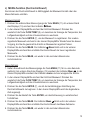
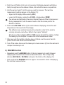
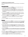
b) MAX/MIN function
• Repeatedly push the MAX/MIN button (9) during measuring to switch between
displaying the maximum and minimum measured values. The corresponding
indicator (REC MAX or REC MIN) is shown at the bottom of the display (13).
• Push and hold the MAX/MIN button for approx. one second to return to displaying
the real-time measured value.

31
c) MEAN function (average value)
You can determine the average value using the number of readings or the measuring
period.
Number of readings
1. During measuring, push the MEAN button (11). The indicator
Mean appears at
the bottom of the display (13).
2. The real-time measured value appears in the lower half of the display. Repeatedly
push the FLOW TEMP button (8) to switch between displaying the temperature,
airow velocity and volume ow.
3. Push the ENTER button (7) to register the reading. This registered reading will
appear in the upper half of the display. Repeat this process until you have registered
the desired number of readings.
4. Push the MEAN button. The indicator
Mean ashes and the calculated average
value of the registered readings is shown in the lower half of the display.
5. Push the MEAN button to return to normal measurement mode.
Measuring period
1. During measuring, push and hold the MEAN button (11) for approx. one second. The
indicator Mean
appears at the bottom of the display (13). The indicator mm/ss
and four horizontal lines appear in the upper half of the display.
2. The real-time measured value appears in the lower half of the display. Repeatedly
push the FLOW TEMP button (8) to switch between displaying the temperature,
airow velocity and volume ow.
3. Push the ENTER button (7) to begin calculating the average value based on the
measuring period. The time lapsed appears in the upper half of the display.
4. If necessary, push the ENTER button to interrupt/continue time measurement.
5. Push the MEAN button. The indicator Mean
ashes and the calculated average
value of the measuring period is shown in the lower half of the display.
6. Push the MEAN button to return to normal measurement mode.

32
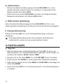
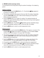
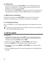
d) HOLD function
• During measuring, push the HOLD ZERO button (12) to freeze the current readings
on the display (13). The indicator HOLD appears at the top of the display.
• Push the HOLD ZERO button again to return to displaying the real-time readings.
The HOLD indicator vanishes.
e) ZERO function (zero setting)
During measuring, push and hold the HOLD ZERO button (12) for approx. one second.
The airow reading will be set to the value zero.
f) Backlight
Push the SET button (10) to activate/deactivate the backlight.
The backlight will not turn off automatically after a time, it must be manually
deactivated.
10. SETTINGS
a) General
1. While in normal measurement mode, push and hold the SET button (10) for approx.
one second to enter the settings menu. The display (13) shows the indicators
SETUP, unit and TEMP.
2. Use the MEAN (11) and FLOW TEMP (8) buttons to navigate through the menu.
3. Push the ENTER button (7) to select the desired menu item.
4. Make your selection using the MEAN and FLOW TEMP buttons and conrm using
the ENTER button.
5. Push and hold the SET button for approx. one second to exit the settings menu.

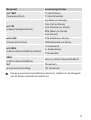
33
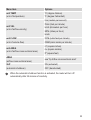
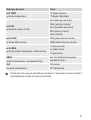
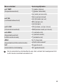
Menu item Options
unit TEMP
(unit of temperature)
ºC (degree Celsius)
ºF (degree Fahrenheit)
unit VEL
(unit of airow velocity)
m/s (meters per second)
ft/min (feet per minute)
km/h (kilometers per hour)
MPH (miles per hour)
knots
unit FLOW
(unit of volume ow)
CFM (cubic feet per minute)
CMM (cubic meter per minute)
unit AREA
(unit of airow cross sectional area)
in
2
(square inches)
m
2
(square meters)
ft
2
(square feet)
AREA
(airow cross sectional area)
see "b) Airow cross sectional area"
SLP
(automatic shutdown)
ON (activated)
OFF (deactivated)
When the automatic shutdown function is activated, the meter will turn off
automatically after 20 minutes of inactivity.

34
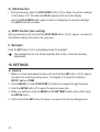
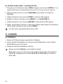
b) Airow cross sectional area
1. Navigate to the menu item AREA and push the ENTER button (7). The four digits in
the lower half of the display (13) begin to ash.
2. Repeatedly push the MAX MIN button (9) to set the number of decimal places.
3. Conrm your selection with the ENTER button. The last digit ashes.
4. Change the value with the MEAN (11) and FLOW TEMP (8) buttons.
5. Conrm your selection with the MAX MIN button. The second last digit ashes.
6. Set the airow cross sectional area value as described above and conrm the
selection with the ENTER button.
The value remains set even after shutdown.
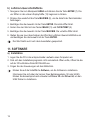
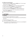
11. SOFTWARE
a) Installation
1. Insert the CD into the corresponding drive of a computer.
2. Should the installation program not open automatically, open the le INSTALLER.exe
from the CD.
3. Follow the instructions on your screen.
Click the button Software to install the software.
Find out whether your operating system is 32 or 64 Bit. Then click either Driver 32
or Driver 64 accordingly to install the USB driver.

35
b) Connecting the meter to a PC
1. Connect the USB cable's Mini-USB plug to the meter's Mini-USB port (5).
2. Connect the USB cable's USB A plug to a free USB port on the computer.
3. Push the on/off button (6) to turn on the product.
4. Open the software.
5. You can nd more information on the software and its functions in the instructions for
use, which you can access via the software help menu.
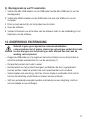
12. MAINTENANCE AND CLEANING
Do not use any aggressive cleaning agents, rubbing alcohol or other
chemical solutions as they can cause damage to the housing and
malfunctioning.
• Before cleaning, disconnect the USB cable from the product and push the metallic
protective sleeve (2) over the sensor head (1).
• Never submerge the product in water.
• There are no components located inside the product you need to maintain. Never
open/dismantle the product.
• To clean the product, a dry, soft and clean cloth is sufcient. Do not apply too much
pressure to the housing to prevent scratching.
• Use a longhaired, soft and clean brush and a vacuum cleaner to easily remove dust.

36
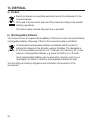
13. DISPOSAL
a) Product
Electronic devices are recyclable waste and must not be disposed of in the
household waste.
At the end of its service life, dispose of the product according to the relevant
statutory regulations.
The built-in battery must be disposed of by a specialist.
b) (Rechargeable) batteries
You as the end user are required by law (Battery Ordinance) to return all used batteries/
rechargeable batteries. Disposing of them in the household waste is prohibited.
Contaminated (rechargeable) batteries are labelled with this symbol to
indicate that disposal in the domestic waste is forbidden. The designations
for the heavy metals involved are: Cd = Cadmium, Hg = Mercury, Pb = Lead
(name on (rechargeable) batteries, e.g. below the trash icon on the left).
Used (rechargeable) batteries can be returned to collection points in your
municipality, our stores or wherever (rechargeable) batteries are sold.
You thus full your statutory obligations and contribute to the protection of the
environment.

37
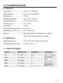
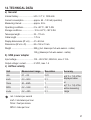
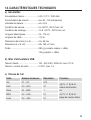
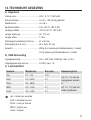
14. TECHNICAL DATA
a) General
Internal battery ............................LiPo / 3.7 V / 1000 mAh
Current consumption ..................approx. 60 – 120 mA (operation)
Measuring interval ......................approx. 0.8 s
Operating conditions ...................0 to +50 ºC, <80 % RH
Storage conditions ......................-10 to +60 ºC, <80 % RH
Telescope length .........................32 – 115 cm
Cable length ...............................1.75 m
Display dimensions (W x H) .......41 x 60 mm
Dimensions (W x H x D) .............62 x 160 x 21 mm
Weight ........................................280 g (incl. telescopic hot-wire sensor + cable)
142 g (telescopic hot-wire sensor + cable)
b) USB power adapter
Input voltage...................... .........100 – 240 V/AC, 50/60 Hz, max. 0.13 A
Output voltage / current.......... ....5 V/DC, max. 1 A
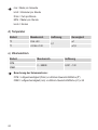
c) Airow velocity
Unit Measurement range Resolution Accuracy
m/s 0.1 – 25 0.01
±(5 % + 1 d) of the
displayed value
or
±(1 % + 1 d) of the
entire measuring
range
km/h 0.3 – 90.0 0.1
ft/min 20 – 4925 1
MPH 0.2 – 55.8 0.1
knots 0.2 – 48.5 0.1
m/s = meters per second
km/h = kilometers per hour
ft/min = feet per minute
MPH = miles per hour

38
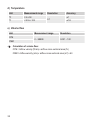
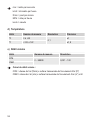
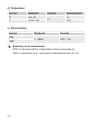
d) Temperature
Unit Measurement range Resolution Accuracy
ºC 0 to +50
0.1
±1
ºF +32 to +122 ±1.8
e) Volume ow
Unit Measurement range Resolution
CFM
0 – 99999 0.001 – 100
CMM
Calculation of volume ow:
CFM = Airow velocity (ft/min) x airow cross sectional area (ft
2
)
CMM = Airow velocity (m/s) x airow cross sectional area (m
2
) x 60
Page is loading ...
Page is loading ...
Page is loading ...
Page is loading ...
Page is loading ...
Page is loading ...
Page is loading ...
Page is loading ...
Page is loading ...
Page is loading ...
Page is loading ...
Page is loading ...
Page is loading ...
Page is loading ...
Page is loading ...
Page is loading ...
Page is loading ...
Page is loading ...
Page is loading ...
Page is loading ...
Page is loading ...
Page is loading ...
Page is loading ...
Page is loading ...
Page is loading ...
Page is loading ...
Page is loading ...
Page is loading ...
Page is loading ...
Page is loading ...
Page is loading ...
Page is loading ...
Page is loading ...
Page is loading ...
Page is loading ...
Page is loading ...
Page is loading ...

Impressum
Dies ist eine Publikation der Conrad Electronic SE, Klaus-Conrad-Str. 1, D-92240 Hirschau (www.conrad.com).
Alle Rechte einschließlich Übersetzung vorbehalten. Reproduktionen jeder Art, z. B. Fotokopie, Mikroverlmung, oder die Erfassung in
elektronischen Datenverarbeitungsanlagen, bedürfen der schriftlichen Genehmigung des Herausgebers. Nachdruck, auch auszugsweise,
verboten. Die Publikation entspricht dem technischen Stand bei Drucklegung.
© Copyright 2014 by Conrad Electronic SE.
Legal notice
This is a publication by Conrad Electronic SE, Klaus-Conrad-Str. 1, D-92240 Hirschau (www.conrad.com).
All rights including translation reserved. Reproduction by any method, e.g. photocopy, microlming, or the capture in electronic data
processing systems require the prior written approval by the editor. Reprinting, also in part, is prohibited. This publication represent the
technical status at the time of printing.
© Copyright 2014 by Conrad Electronic SE.
Information légales
Ceci est une publication de Conrad Electronic SE, Klaus-Conrad-Str. 1, D-92240 Hirschau (www.conrad.com).
Tous droits réservés, y compris de traduction. Toute reproduction, quelle qu‘elle soit (p. ex. photocopie, microlm, saisie dans des
installations de traitement de données) nécessite une autorisation écrite de l‘éditeur. Il est interdit de le réimprimer, même par extraits.
Cette publication correspond au niveau technique du moment de la mise sous presse.
© Copyright 2014 par Conrad Electronic SE.
Colofon
Dit is een publicatie van Conrad Electronic SE, Klaus-Conrad-Str. 1, D-92240 Hirschau (www.conrad.com).
Alle rechten, vertaling inbegrepen, voorbehouden. Reproducties van welke aard dan ook, bijvoorbeeld fotokopie, microverlming of de
registratie in elektronische gegevensverwerkingsapparatuur, vereisen de schriftelijke toestemming van de uitgever. Nadruk, ook van
uittreksels, verboden. De publicatie voldoet aan de technische stand bij het in druk bezorgen.
© Copyright 2014 by Conrad Electronic SE.
V2_0814_02-HK
-
 1
1
-
 2
2
-
 3
3
-
 4
4
-
 5
5
-
 6
6
-
 7
7
-
 8
8
-
 9
9
-
 10
10
-
 11
11
-
 12
12
-
 13
13
-
 14
14
-
 15
15
-
 16
16
-
 17
17
-
 18
18
-
 19
19
-
 20
20
-
 21
21
-
 22
22
-
 23
23
-
 24
24
-
 25
25
-
 26
26
-
 27
27
-
 28
28
-
 29
29
-
 30
30
-
 31
31
-
 32
32
-
 33
33
-
 34
34
-
 35
35
-
 36
36
-
 37
37
-
 38
38
-
 39
39
-
 40
40
-
 41
41
-
 42
42
-
 43
43
-
 44
44
-
 45
45
-
 46
46
-
 47
47
-
 48
48
-
 49
49
-
 50
50
-
 51
51
-
 52
52
-
 53
53
-
 54
54
-
 55
55
-
 56
56
-
 57
57
-
 58
58
-
 59
59
-
 60
60
-
 61
61
-
 62
62
-
 63
63
-
 64
64
-
 65
65
-
 66
66
-
 67
67
-
 68
68
-
 69
69
-
 70
70
-
 71
71
-
 72
72
-
 73
73
-
 74
74
-
 75
75
-
 76
76


VOLTCRAFT PL-135 HAN Operating Instructions Manual
- Type
- Operating Instructions Manual
Ask a question and I''ll find the answer in the document
Finding information in a document is now easier with AI
in other languages
- français: VOLTCRAFT PL-135 HAN
- Deutsch: VOLTCRAFT PL-135 HAN
- Nederlands: VOLTCRAFT PL-135 HAN
Related papers
-
VOLTCRAFT SPS-1200/R Operating instructions
-
-
-
VOLTCRAFT 2176717 User manual
-
-
VOLTCRAFT SL-10 Operating Instructions Manual
-
-
VOLTCRAFT PL-100TRH Operating Instructions Manual
-
-
Other documents
-
Renkforce EMT2500ET Owner's manual
-
Renkforce 7 ports USB 2.0 hub Steel casing, wall mount option Owner's manual
-
-
TOOLCRAFT 2499003 User manual
-
TOOLCRAFT 2751630 User manual
-
TOOLCRAFT 2612818 1000lm LED Torch Light User manual
-
Tristar KA-5283 User manual
-
Sygonix 2373341 User manual
-
-
 Conrad energy Non-standard battery (rechargeable) 18650 Li-ion 18650 USB 3.7 V 1400 mAh 2 pc(s) Operating instructions
