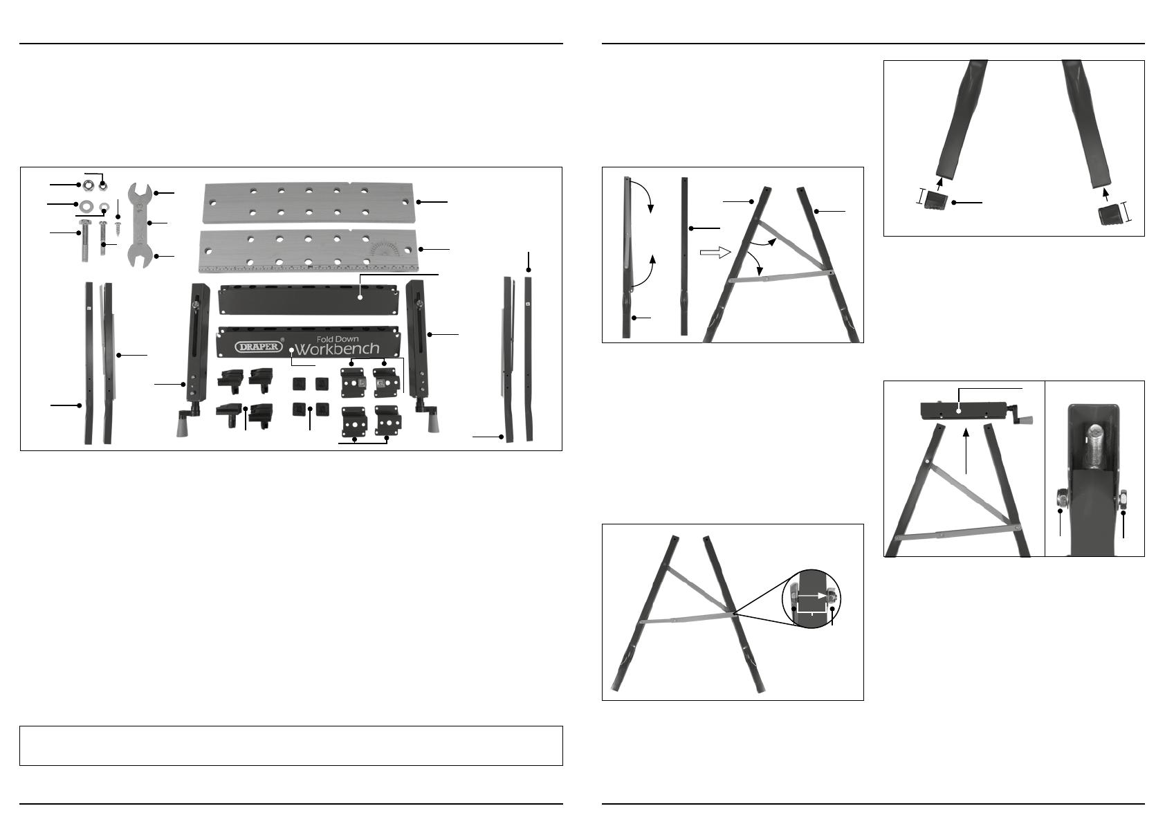
Draper 77020 Operating instructions

Type
Operating instructions

The Draper 77020 is a versatile and sturdy 600mm workbench, ideal for a variety of tasks around the home, garage, or workshop. With a durable steel frame and a maximum load capacity of 100kg, it can handle even the most demanding projects. The workbench features adjustable clamping blocks for securing workpieces, tool holders for keeping your tools organized, and a crank handle for easy height adjustment. Whether you're a DIY enthusiast or a professional tradesperson, the Draper 77020 is a valuable addition to your workshop.

The Draper 77020 is a versatile and sturdy 600mm workbench, ideal for a variety of tasks around the home, garage, or workshop. With a durable steel frame and a maximum load capacity of 100kg, it can handle even the most demanding projects. The workbench features adjustable clamping blocks for securing workpieces, tool holders for keeping your tools organized, and a crank handle for easy height adjustment. Whether you're a DIY enthusiast or a professional tradesperson, the Draper 77020 is a valuable addition to your workshop.

77020
EN
Original Instructions
Version 1
600MM FOLD DOWN
WORKBENCH
2. Contents
– 3 –
EN
1.1 Product Reference
User Manual for: 600mm Fold Down Workbench
Stock No: 77020
Part No: WB600Y
1.2 Revisions
Version 1: August 2012
First release
Version 2: April 2021
General content and formatting updates
Version 3: July 2022
General content revision
As our manuals are continually updated,
always ensure that the latest version is used.
Download the latest version from:
drapertools.com/manuals
1.3  Understanding the Safety Content
of This Manual
WARNING! – Situations or actions that may result in
personal injury or death.
CAUTION! – Situations or actions that may result in
damage to the product or surroundings.
Important: – Information or instructions of particular
importance.
1.4 Copyright © Notice
Copyright © Draper Tools Limited.
Permission is granted to reproduce this manual for
personal and educational use ONLY. Commercial
copying, redistribution, hiring, or lending is strictly
prohibited.
No part of this manual may be stored in a retrieval system
or transmitted in any other form or means without written
permission from Draper Tools Limited.
In all cases, this copyright notice must remain intact.
1. Preface
– 2 –
These are the original product instructions. This
document is part of the product; retain it for the life
of the product, passing it on to subsequent holders.
Read this manual in full before attempting to
assemble, operate, or maintain this product.
This Draper Tools manual describes the purpose
of the product and contains all the necessary
information to ensure its correct and safe use.
Following all the instructions and guidance in
this manual will ensure the safety of both the
product and the operator and increase the
lifespan of the product.
All photographs and drawings within this manual are
supplied by Draper Tools to help illustrate correct
operation of the product.
Every eort has been made to ensure the
information contained in this manual is accurate.
However, Draper Tools reserves the right to amend
this document without prior warning. Always use the
latest version of the product manual.
1. Preface 2
1.1 Product Reference 2
1.2 Revisions 2
1.3 Understanding the Safety Content of This Manual 2
1.4 Copyright © Notice 2
2. Contents 3
3. Warranty 4
4. Product Introduction 5
4.1 Scope 5
4.2 Specication 5
5. Health and Safety Information 6
5.1 General Health and Safety Instructions 6
6. Identication and Unpacking 7
6.1 Product Overview 7
6.2 What’s in the Box? 8
7. Assembly Instructions 9
7.1 Assemble the Legs 9
7.2 Attach the Top Frames 9
7.3 Attach the Crossbars 10
7.4 Attach the U-Brackets to the Top Frames 10
7.5 Attach the Benchtops 12
7.6 Finishing Touches 12
8. Operating Instructions 13
8.1 Unfolding and Folding the Workbench 13
8.2 Clamping a Workpiece 13
9. Storage, Spares and Disposal 14
10. Explanation of Symbols 15
4. Product Introduction
Stock No. 77020
Part No. WB600Y
Dimensions:
Folded: W 605 x H 950 x D 240mm
Unfolded: W 605 x H 785 x D 640mm
Max. clamping width: 260mm
Max. load capacity: 100kg (evenly distributed)
Net weight: 6.7kg
– 5 –
EN
4.2 Specication
4.1 Scope
This folding workbench is designed for use as a portable
work surface and saw horse with customisable clamping
arrangements. Any other application beyond the
conditions established for use will be considered misuse.
Draper Tools accepts no responsibility for improper use of
this product.
Part of our core range, this product is suitable for regular
use by enthusiasts and tradespersons alike.
WARNING! This product is not a toy and must be
respected.
Read this manual in full before attempting to assemble,
operate or maintain the product, and retain it for later use.
3. Warranty
Draper Tools products are carefully tested and inspected
before shipment and are guaranteed to be free from
defective materials and workmanship.
Should the tool develop a fault, return the complete tool
to your nearest distributor or contact Draper Tools
directly. Contact information can be found at the back of
this manual.
Proof of purchase must be provided.
If, upon inspection, it is found that the fault occurring is
due to defective materials or workmanship, repairs will
be carried out free of charge. This warranty period covers
parts and labour for 12 months from the date of
purchase. Where tools have been hired out, the warranty
period covers 90 days from the date of purchase.
This warranty does not apply to any consumable parts,
batteries or normal wear and tear, nor does it cover any
damage caused by misuse, careless or unsafe handling,
alterations, accidents, or repairs attempted or made by
any personnel other than the authorised Draper Tools
repair agent.
In all cases, to make a claim for faulty workmanship or
materials within the standard warranty period, please
contact or return the product to the place of purchase.
Proof of purchase may be required.
If the place of purchase is no longer trading or if you
experience any diculties with your warranty, please
contact Customer Services with the product details and
your proof of purchase. Contact details can be found at
the back of this manual.
If the tool is not covered by the terms of this warranty,
repairs and carriage charges will be quoted and charged
accordingly.
This warranty supersedes any other guarantees
expressed or implied and variations of its terms are not
authorised.
Your Draper Tools guarantee is not eective until you can
produce, upon request, a dated receipt or invoice to
verify your purchase within the guarantee period.
Please note that this warranty is an additional benet
and does not aect your statutory rights.
Draper Tools Limited
– 4 –
6. Identication and Unpacking
6.1 Product Overview
– 7 –
EN
5. Health and Safety Information
– 6 –
EN
(1) Benchtop
(2) Crank handles
(3) Front legs
(4) Rear legs
(5) Clamp blocks
(6) Tool holders
(7) Folding braces
(8) Diagonal braces
Important: Read all Health and Safety instructions before attempting to operate, maintain or repair this product.
Non-compliance with these instructions may result in injury or damage to the user or the product.
5.1 General Health and Safety Instructions
• Observe all standard safety precautions and good
practices when in a workshop environment.
• Read all the safety information associated with any
tools to be used in conjunction with this workbench.
Use all appropriate personal protective equipment
when working with tools.
Be mindful that tools that may damage the
workbench frame or work surface if used carelessly.
• Before every use, inspect the workbench for broken,
cracked, loose or corroded parts.
Important: DO NOT use this product if it is damaged
or its structural integrity is compromised. Contact
Draper Tools to discuss repair and replacement
options.
• Ensure that the workbench is fully assembled, opened
and tightened before use, with the folding braces
locked in place.
• Ensure that the workbench is positioned on rm and
level ground while it is in use.
DO NOT use the workbench on slippery or wet
surfaces.
• DO NOT climb or stand on the workbench.
• DO NOT exceed the rated weight limit.
DO NOT store heavy loads on the workbench for
extended periods.
• Position the workpiece so that the weight is evenly
distributed and does not overbalance the workbench.
• NEVER clamp or mount tools to the workbench.
• DO NOT expose the product to rain or wet
environments.
• Take care when lifting or moving the workbench.
CAUTION! DO NOT overtighten the clamps.
(1)
(7)
(2)
(3)
(5)
(6)
(8)
(4)
(4)
6. Identication and Unpacking
Please visit drapertools.com for our full range of accessories and consumables.
EN
– 9 –– 8 –
EN
1Fig.
3Fig.
4Fig.
2Fig.
Important: Read and understand all the safety
instructions listed in this manual before attempting
to assemble this product.
Important: Ensure all bolts are only FINGER TIGHT until
assembly is complete. Then tighten all xtures securely.
7.1 Assemble the Legs
7.2 Attach the Top Frames
1. Place the rear left leg (C) on your left and the front
left leg (A) on your right so that the indented sides are
at the bottom and facing towards you.
Important: The folding brace should also be facing
towards you.
2. Open the folding brace (7) and the diagonal brace
(8) and align them with the hole halfway up the left
front leg.
Important: The leg should be positioned between the
two braces, with the lipped edges of the braces facing
upward. The folding leg should be able to fold upward.
3. Pass an M8 x 45mm half-thread hex bolt (N) through
both braces and the leg and secure them in place
with an M8 nylon-insert lock nut (S).
Important: Place an M8 washer (Q) between each
brace and the leg to ensure smooth folding.
4. Attach a foot (M) to the indented end of each leg so
that the longest edge is positioned outwardly on the
same side as the folding brace.
5. Repeat these steps for the front right (B) and rear right
(D) legs, with the rear leg on your left and the front
leg on your right.
6. Insert the upper ends of the left leg assembly
between the brackets of a top frame (I) so that the
holes align and the crank handle (2) is positioned
above the front leg (A).
7. Pass two M8 x 45mm half-thread hex bolts (N) each
through an M8 washer (Q) and top frame bracket
around the leg and secure each in place with another
M8 washer and an M8 nylon-insert lock nut (S).
8. Repeat these steps for the right leg assembly,
ensuring that the crank handle is positioned over
the front leg.
7. Assembly Instructions
6.3 Packaging
Keep the product packaging for the duration of the
warranty period for reference should the product need to
be returned for repair.
WARNING! Keep packaging materials out of reach
of children. Dispose of packaging correctly and
responsibly and in accordance with local regulations.
(A) 1 x Front left leg
(B) 1 x Front right leg
(C) 1 x Rear left leg
(D) 1 x Rear right leg
(E) 1 x Front crossbar
(F) 1 x Rear crossbar
(G) 1 x Front benchtop
(H) 1 x Rear benchtop
(I) 2 x Top frames
(J) 2 x U-brackets (bare)
(K) 2 x U-brackets with guide plates
(L) 4 x Clamp blocks
(M) 4 x Feet
(N) 6 x M8 x 45mm half-thread hex bolts
(O) 8 x M6 x 37mm half-thread screws
(P) 16 x M5 x 16mm self-tapping screws
(Q) 12 x M8 washers
(R) 8 x M6 washers
(S) 6 x M8 nylon-insert lock nuts
(T) 8 x M6 nylon-insert lock nuts
(U) 1 x Spanner tool
U1. M8 spanner
U2. M6 spanner
6.2 What’s in the Box?
Carefully remove the product from the packaging and
examine it for any signs of damage that may have
occurred during shipment.
Before assembling the product, lay the contents out and
check them against the parts shown below. If any part is
damaged or missing, do not attempt to use the product.
Please contact the Draper Tools Helpline; contact details
can be found at the back of this manual.
(D)
(C)
(A)
(U2)
(U)
(O)
(U1)
(I)
(H) (A)
(C)
(A)
(G)
(M)
(I)
(F)
(E)
(L) (M) (J)
(K)
(B)
(P)
(T)
(S)
(Q)
(N)
(R)
(C)
(I)
(N)
(Q, S)
(N) (S)
(Q)
EN
EN
7. Assembly Instructions7. Assembly Instructions
5Fig.
8Fig.
9Fig.
10Fig.
11Fig.
12Fig.
7Fig.
6Fig.
7.3 Attach the Crossbars
7.4 Attach the U-Brackets to the Top Frames
1. Insert the front left leg (A) between the left brackets
of the front crossbar (E) so that the holes align.
Important: The crossbar brackets can be shaped
to t comfortably around the leg as required.
2. Pass two M6 x 37mm half-thread screws (O) through
the front crossbar brackets around the front left leg
and secure each in place with an M6 washer (R) and
an M6 nylon-insert lock nut (T).
3. Insert the front right leg (B) between the right
brackets of the front crossbar so that the holes align.
4. Pass two M6 x 37mm half-thread screws (O) through
the front crossbar brackets around the front right leg
and secure each in place with an M6 washer (R) and
an M6 nylon-insert lock nut (T).
5. Place the rear crossbar (F) between the rear legs and
align the holes.
6. Secure the rear crossbar in place using four
M6 x 37mm half-thread screws (O), M6 washers (R)
and M6 nylon-insert lock nuts (T).
Important: Once assembled, the legs should bend
outwards slightly at the bottom to improve the
stability of the workbench.
1. Remove the two screws near the crank handle (2) in
the left top frame.
2. With the bracket arms extended upwards, align
a bare U-bracket (J) with the holes and screw it
into place.
5. Slide the guide plate under the top of the top frame
and pass the screw down through the U-bracket to
secure it into place.place.
6. Replace the M10 nut above the U-bracket.
Important: DO NOT overtighten the guide plate
screw or M10 nut as this will stop the crank handle
from operating smoothly.
7. Repeat these steps for the right top frame.
3. Unscrew the M10 nut (9) from the left top frame and
unscrew the plate from a U-bracket with guide plate
(K).
4. Place the centre hole of the U-bracket over the M10
bolt in the top frame so that the bracket arms extend
upwards and the two smaller holes are positioned
above the slot.
– 10 – – 11 –
(9)
(J)
(E)
(A)
(K)
(I)
(2)
– 13 –
EN
8. Operating Instructions
Important: Before using this product, read and understand
all the safety instructions listed in this manual.
8.1 Unfolding and Folding the Workbench
1. To unfold the workbench:
a. Pull the front and rear legs apart.
b. Press down on the folding braces (7) to lock the
legs in position.
2. To fold the workbench away:
a. Ensure that the crank handles are not in the
downward position so as not to damage or obstruct
the legs when folding.
b. Lift the folding braces (7) upwards to unlock
the legs.
c. Push the front and rear legs together until the
workbench is fully closed.
EN
7. Assembly Instructions
7.5 Attach the Benchtops 7.6 Finishing Touches
Important: The nylon inserts inside the nuts should
be broken when securely tightened. This provides
additional security against the accidental loosening of
bolts during use.
Important: When complete, the folding braces between
the front and rear legs should be on the outside of the
frame and should fold upwards when the workbench is
closed.
1. Place the rear benchtop (H) onto the rear U-brackets
so that the eight small holes align with the brackets
and the notch is on the inside edge.
2. Screw eight M5 x 16mm self-tapping screws (P) up
through the brackets and into the benchtop.
Important: LOOSELY insert all eight screws before
tightening them to ensure that all of the holes align
correctly.
3. Repeat these steps for the front benchtop (G),
keeping the ruled edge towards the crank handles.
13Fig.
15Fig.
14Fig.
8.2 Clamping a Workpiece
Workpieces can be clamped directly between the
benchtop pieces or between the clamp blocks. The
clamp blocks can be repositioned as required to
accommodate workpieces of varying shapes and sizes.
The notches in the benchtop pieces can be used to grip
pipes and tubing.
1. Position the clamp blocks (5) in the appropriate holes
of the benchtop as required.
2. Use the crank handles (2) to separate or bring
together the benchtop pieces as appropriate to grip
the workpiece:
To separate the benchtop pieces, turn both crank
handles anticlockwise.
To bring the benchtop pieces together, turn both
crank handles clockwise.
16Fig.
Important: Adjust both crank handles together to open
or close the benchtop evenly.
The crossbars may be used to store tools.
– 12 –
(H)
(P)
(7)
10. Explanation of Symbols
– 15 –
EN
– 14 –
EN
Read the instruction manual
9. Storage, Spares and Disposal
Store the workbench in a clean and dry location, out of
direct sunlight and out of reach o children.
Important: DO NOT store heavy loads on the workbench
for extended periods.
For spare parts, servicing, and repair and replacement
options, please contact the Draper Tools Product
Helpline for details of your nearest authorised agent.
Draper Tools will endeavour to hold any spare parts, if
applicable, for seven years from the date that it sells the
nal matching stock item.
Any servicing or repairs carried out by unauthorised
personnel or installation of spare parts not supplied by
Draper Tools will invalidate your warranty.
At the end of its working life, dispose of the product
responsibly and in line with local regulations. Recycle
where possible.
© Published by Draper Tools Limited
Delta International
Delta International BV
Oude Graaf 8
6002 NL
Weert
Netherlands
Contact Details
Draper Tools
Draper Tools Limited
Hursley Road
Chandler’s Ford
Eastleigh
Hampshire
SO53 1YF
UK
Website: drapertools.com
Product Helpline: +44 (0) 23 8049 4344
Telephone Sales Desk: +44 (0) 23 8049 4333
General Enquiries: +44 (0) 23 8026 6355
General Fax: +44 (0) 23 8026 0784
Please contact the Draper Tools Product Helpline for repair and servicing enquiries.
  • Page 1 1
  • Page 2 2
  • Page 3 3
  • Page 4 4
  • Page 5 5
  • Page 6 6
  • Page 7 7
  • Page 8 8
  • Page 9 9

Draper 77020 Operating instructions

Type
Operating instructions

The Draper 77020 is a versatile and sturdy 600mm workbench, ideal for a variety of tasks around the home, garage, or workshop. With a durable steel frame and a maximum load capacity of 100kg, it can handle even the most demanding projects. The workbench features adjustable clamping blocks for securing workpieces, tool holders for keeping your tools organized, and a crank handle for easy height adjustment. Whether you're a DIY enthusiast or a professional tradesperson, the Draper 77020 is a valuable addition to your workshop.

Ask a question and I''ll find the answer in the document

Finding information in a document is now easier with AI