Hitachi CPA100 Operating instructions

Category
Projector accessories
Type
Operating instructions

Hitachi CPA100 provides a secure and flexible way to mount your projector on a wall, supporting up to 50 lbs of weight. With its versatile design, it can be installed on various surfaces, including wood studs, wood beams, solid concrete, cinder blocks, and metal studs (with an accessory kit). The wall arm allows for precise positioning of the projector, ensuring optimal viewing angles and image quality. Its sturdy construction and easy installation make it an ideal choice for home theaters, classrooms, offices, and other settings.

Hitachi CPA100 provides a secure and flexible way to mount your projector on a wall, supporting up to 50 lbs of weight. With its versatile design, it can be installed on various surfaces, including wood studs, wood beams, solid concrete, cinder blocks, and metal studs (with an accessory kit). The wall arm allows for precise positioning of the projector, ensuring optimal viewing angles and image quality. Its sturdy construction and easy installation make it an ideal choice for home theaters, classrooms, offices, and other settings.

ISSUED: 03-17-08 SHEET #:055-9499-3 05-23-08
Visit the Peerless Web Site at www.peerlessmounts.com For customer care call 1-800-865-2112 or 708-865-8870.
1 of 12
Installation and Assembly: Hitachi Short Throw Wall Arm
Model: CPA100WALLARM
3215 W. North Ave. • Melrose Park, IL 60160 • (800) 865-2112 or (708) 865-8870 • Fax: (708) 865-2941 • www.peerlessmounts.com
Maximum Load Capacity: 50 lb (22.7 kg)
ISSUED: 03-17-08 SHEET #:055-9499-3 05-23-08
Visit the Peerless Web Site at www.peerlessmounts.com For customer care call 1-800-865-2112 or 708-865-8870.
2 of 12
NOTE: Read entire instruction sheet before you start installation and assembly.
Do not begin to install your Peerless product until you have read and understood the instructions and warnings
contained in this Installation Sheet. If you have any questions regarding any of the instructions or warnings, please
call Peerless customer care at 1-800-865-2112.
This product should only be installed by someone of good mechanical aptitude, has experience with basic building
construction, and fully understands these instructions.
Make sure that the supporting surface will safely support the combined load of the equipment and all attached hard-
ware and components.
Never exceed the Maximum Load Capacity. See page one.
If mounting to wood wall studs, make sure that mounting screws are anchored into the center of the studs. Use of an
"edge to edge" stud finder is highly recommended.
Always use an assistant or mechanical lifting equipment to safely lift and position equipment.
Tighten screws firmly, but do not overtighten. Overtightening can damage the items, greatly reducing their holding
power.
This product is intended for indoor use only. Use of this product outdoors could lead to product failure and personal
injury.
This product was designed and intended to be mounted to the following supporting surfaces checked below with the
hardware included in this product as specified in the installation sheet. To mount this product to an alternative support-
ing surface, contact Peerless customer care at 1 800 865-2112.
This product was designed to be installed on the following wall construction only;
WALL CONSTRUCTION ADDITIONAL HARDWARE REQUIRED
x Wood Stud None
x Wood Beam None
x Solid Concrete None
x Cinder Block None
x Metal Stud Do not attach except with Peerless accessory kit for metal studs;
Contact Customer Service for Peerless accessory kit for metal studs.
Brick Contact Customer Service
Other or unsure? Contact Customer Service
WARNING
Tools Needed for Assembly
stud finder ("edge to edge" stud finder is recommended)
phillips screwdriver
drill
1/4" bit for concrete and cinder block wall
1/2" bit for metal stud wall
5/32" bit for metal or wood stud wall
level
ISSUED: 03-17-08 SHEET #:055-9499-3 05-23-08
Visit the Peerless Web Site at www.peerlessmounts.com For customer care call 1-800-865-2112 or 708-865-8870.
3 of 12
Description Qty. Part #
A
slide plate 1 055-1821
B
projector mount assembly 1 055-1803
C
#10-32 x 3/8" serrated washer head socket pin screw 2 520-1151
D
#10-32 x 1/4" socket pin screw 1 520-1196
E
5/32" (4 mm) security allen wrench 1 560-9646
F
6.5 ID flat washer 2 540-1078
G
#14 x 2.5" wood screw 4 5S1-015-C03
H
Alligator
®
anchor 4 590-0097
I
3/32" (2 mm) security allen wrench 1 560-1097
J
wall arm 1 055-1820
K
wall plate 1 055-1818
L
adapter plate 1 055-1822
M
1/4-20 x 1" hex head screw 2 520-1606
N
1/4" ID spacer 2 560-1723
O
0.509" ID spacer 2 590-1270
P
0.376 ID shoulder spacer 2 590-1269
Q
rectangle plug 1 590-1302
R
circle plug 2 590-1301
S
2" rubber grommet 1 560-1726
T
1.75" rubber grommet 1 560-1168
U
M6 x 12 mm serrated washer head socket pin screw 8 510-1050
V
washer fender 4 540-1008
W
vinyl trim 1 600-1012
X
0.25" spacer 4 590-1050
Parts List
Parts may appear slightly different than illustrated.
Before you begin, make sure all parts shown are included with your product.
B
C
A
D
G
E
H
F
I
O
JK L MN
P
Q
R
U
V
W
X
S T
ISSUED: 03-17-08 SHEET #:055-9499-3 05-23-08
Visit the Peerless Web Site at www.peerlessmounts.com For customer care call 1-800-865-2112 or 708-865-8870.
4 of 12
NOTE: Use the chart (see fig 1.1) below to determine the placement of projector in relation to mounting location of
wall arm. Chart numbers will have a 3% discrepancy due to the optics of the projector. Prior to installing projector,
physically test the projection size and distance while having the actual projector in the desired location before
installing, this will determine the exact mounting position.
Projector Position
1
fig. 1.1
SCREEN/WHITEBOARD
3.65
93
(X)
CENTER OF
WALL ARM
CENTER OF
LENS
fig. 1.2
* The distance from the bottom of the
projector to the top of the screen.
(Z)
Screen size
( X )
inch inch cm inch cm
63 4.7 11.9 11.8 30.0
70 6.8 17.2 12.8 32.6
77 8.9 22.5 13.8 35.1
80 9.8 24.8 14.3 36.2
90 12.8 32.4 15.7 39.9
100 15.7 39.9 17.2 43.6
Throw Distance
( Y )
Image Offset *
( Z )
THROW DISTANCE: ( Y )
(The distance from projector edge to screen surface)
3.9 in
NOTE: Lens is not centered to the wall arm
14.8 in
ISSUED: 03-17-08 SHEET #:055-9499-3 05-23-08
Visit the Peerless Web Site at www.peerlessmounts.com For customer care call 1-800-865-2112 or 708-865-8870.
5 of 12
Use a stud finder to locate the edges of the studs. Use of an edge-to-edge stud finder is highly recommended. Based
on their edges, draw a vertical line down each stud’s center. Place wall plate (K) on wall as a template. Level plate,
and mark the center of the four mounting holes. Make sure that the mounting holes are on the stud centerline. Drill
four 5/32" (4 mm) dia. holes 2-1/2" (65 mm) deep. Make sure that the wall plate (K) is level, secure it using four
#14 x 2.5" wood screws (G) and fender washers (V) as shown in figure 2.1.
Installation to Wood Stud Wall
Installer must verify that the supporting surface will safely support the combined load of the equipment and all attached
hardware and components.
Tighten wood screws so that wall plate is firmly attached, but do not overtighten. Overtightening can damage the
screws, greatly reducing their holding power.
Never tighten in excess of 80 in. • lb (9 N.M.).
Make sure that mounting screws are anchored into the center of the stud. The use of an "edge to edge" stud finder is
highly recommended.
Hardware provided is for attachment of mount through standard thickness drywall or plaster into wood studs. Installers
are responsible to provide hardware for other types of mounting situations.
WARNING
fig. 2.1
G
K
V
2
ISSUED: 03-17-08 SHEET #:055-9499-3 05-23-08
Visit the Peerless Web Site at www.peerlessmounts.com For customer care call 1-800-865-2112 or 708-865-8870.
6 of 12
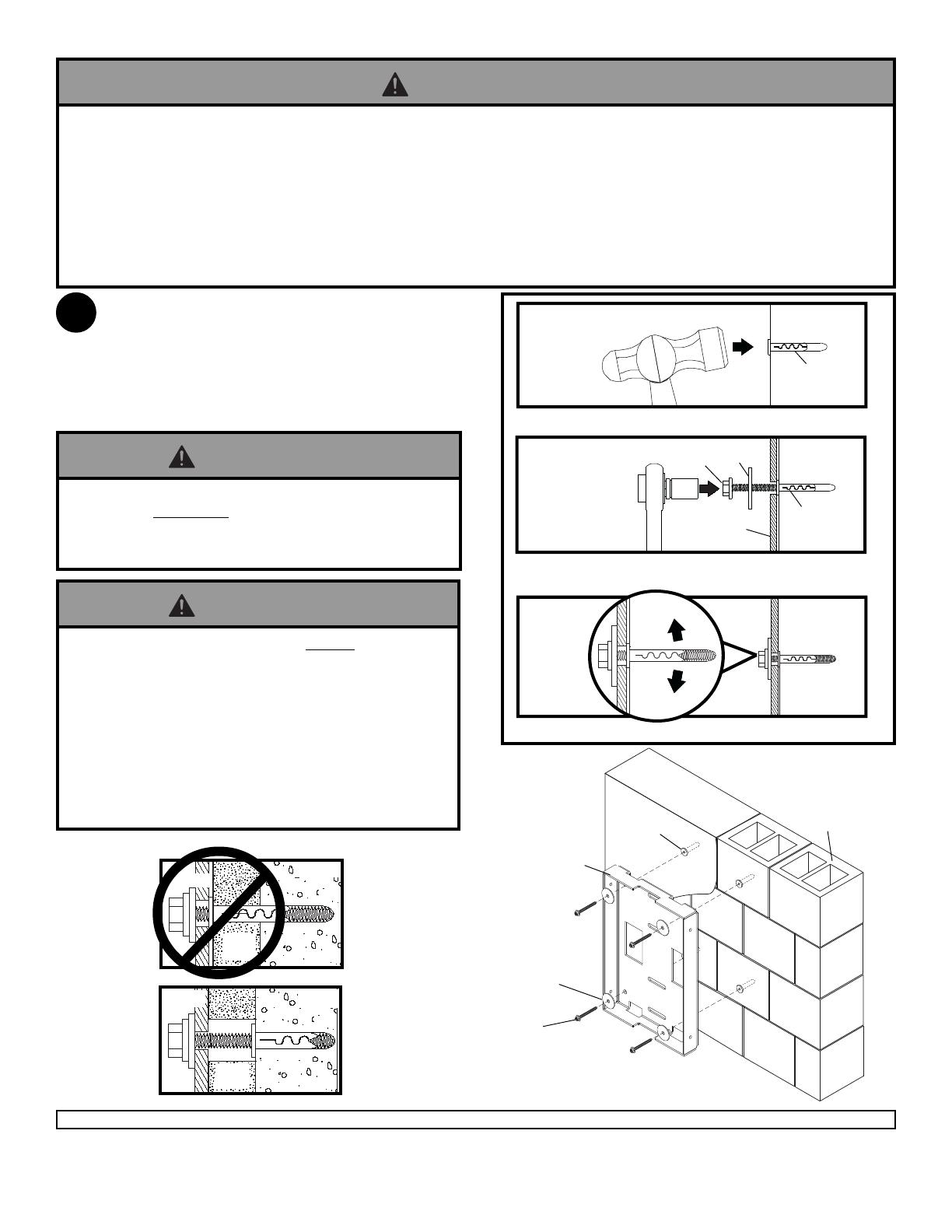
Make sure that wall plate (K) is level, use it as a
template to mark four mounting holes. Drill four 1/4"
(6 mm) dia. holes to a minimum depth of 2.5" (65 mm).
Insert anchors (H) in holes flush with wall as shown
(right). Place wall plate over anchors and secure with
four #14 x 2.5" screws (G) and fender washers (V).
Level, then tighten all fasteners.
Installation to Solid Concrete or Cinder Block
When installing Peerless wall mounts on cinder block, verify that you have a minimum of 1-3/8" of actual concrete
thickness in the hole to be used for the concrete anchors. Do not drill into mortar joints! Be sure to mount in a solid
part of the block, generally 1" minimum from the side of the block. Cinder block must meet ASTM C-90 specifications.
It is suggested that a standard electric drill on slow setting is used to drill the hole instead of a hammer drill to avoid
breaking out the back of the hole when entering a void or cavity.
Concrete must be 2000 psi density minimum. Lighter density concrete may not hold concrete anchor.
Make sure that the supporting surface will safely support the combined load of the equipment and all attached hard-
ware and components.
WARNING
CONCRETE
SURFACE
1
3
2
H
Drill holes and insert anchors (H).
Place plate (K) over anchors (H) and secure with screws (G)
and fender washers (V).
Tighten all fasteners.
K
H
G
CUTAWAY VIEW
INCORRECT
CORRECT
wall plate
plaster/
dry wall
concrete
wall plate
concrete
plaster/
dry wall
Always attach concrete anchors directly to load-
bearing concrete.
Never attach concrete anchors to concrete covered
with plaster, drywall, or other finishing material. If
mounting to concrete surfaces covered with a finishing
surface is unavoidable, the finishing surface must be
counterbored as shown below. Be sure concrete
anchors do not pull away from concrete when tighten-
ing screws. If plaster/drywall is thicker than 5/8",
custom fasteners must be supplied by installer.
WARNING
Tighten screws so that wall plate is firmly attached,
but do not overtighten. Overtightening can damage
screws, greatly reducing their holding power.
Never tighten in excess of 80 in. • lb (9 N.M.).
WARNING
G
K
V
SOLID CONCRETE
CINDER BLOCK
H
V
Always attach concrete anchors directly to load-
bearing concrete.
Never attach concrete anchors to concrete covered
with plaster, drywall, or other finishing material. If
mounting to concrete surfaces covered with a finishing
surface is unavoidable, the finishing surface must be
counterbored as shown below. Be sure concrete
anchors do not pull away from concrete when tighten-
ing screws. If plaster/drywall is thicker than 5/8",
custom fasteners must be supplied by installer.
WARNING
2
ISSUED: 03-17-08 SHEET #:055-9499-3 05-23-08
Visit the Peerless Web Site at www.peerlessmounts.com For customer care call 1-800-865-2112 or 708-865-8870.
7 of 12
Wall plate (K) can be mounted to single metal stud. Use a stud finder to locate the edges of the stud. Use of an
edge-to-edge stud finder is highly recommended. Based on it's edges, draw a vertical line down stud’s center. Place
wall plate on wall as a template. Level plate, and mark the center of the four mounting holes. Make sure that the
mounting holes are on the stud centerline. Drill four 1/2" holes through drywall and metal stud. NOTE: It may be
necessary to drill 5/32" pilot holes prior to drilling 1/2" holes.
Refer to instruction sheet included with Peerless accessory kit ACC 415 for metal studs to install togglers.
Loosely fasten wall plate (K) to wall using four 1/4-20 x 2-1/2" screws as shown in figure 2.2.
Level, hold, and then tighten all screws.
Drywall must be 1/2" or thicker, and metal stud must be 24 gauge or thicker.
Installer must verify that the supporting surface will safely support the combined load of the equipment and all attached
hardware and components.
WARNING
Installation to Metal Stud Wall (Metal Stud Accessory Kit ACC 415 Required)
TOGGLER
(NOT INCLUDED)
K
fig. 2.2
1/4-20 X 2-1/2"
PHILLIPS SCREWS
(NOT INCLUDED)
2
ISSUED: 03-17-08 SHEET #:055-9499-3 05-23-08
Visit the Peerless Web Site at www.peerlessmounts.com For customer care call 1-800-865-2112 or 708-865-8870.
8 of 12
Hook wall arm (J) onto wall plate (K) as shown in
fig. 3.2 or for additional vertical adjustment fig. 3.3.
Run cords through desired opening at this point.
fig. 3.3
SUPPORTING
SURFACE NOT
SHOWN FOR
CLARITY
Disengage connection block from projector mount
assembly (B) by unscrewing captive screw and sliding
out connection block as shown.
K
J
3
4
K
J
OR
fig. 3.2
fig. 3.1
K
W
Place vinyl trim (W) onto bottom or top of wall plate (K)
where cords will be routed as shown in fig. 3.1.
Secure arm to wall plate (K) using four M6 x 12 mm
serrated washer head socket pin screws (U) as
shown in fig. 3.4. Cut 1.75" rubber grommet (T) in
half and place into half moons on top and bottom of
wall arm (J). Insert circle plug (R) or 2" rubber
grommet (S) into arm fig. 3.4.
3-2
3-2
CONNECTION
BLOCK
CAPTIVE
SCREW
B
fig. 3.4
1.75" RUBBER
GROMMET
(CUT IN HALF)
1/2 OF
GROMMET (T)
1/2 OF
GROMMET (T)
J
U
T
R
R
S
OR
3-2
3-1
NOTE: If cords inserted through top or bottom openings, use
vinyl trim. Otherwise insert cords through secondary openings
on wall face as shown in fig. 3.2 and 3.3.
Secondary
Openings
ISSUED: 03-17-08 SHEET #:055-9499-3 05-23-08
Visit the Peerless Web Site at www.peerlessmounts.com For customer care call 1-800-865-2112 or 708-865-8870.
9 of 12
NOTE: Do not tighten 1/4-20 x 1" hex head screws (M) fully to allow for adjustment. Fasten projector mount
assembly (B) to wall arm (J) using two 1/4-20 x 1" hex head screws (M), 0.509" ID spacers (O), 1/4"ID spacers (N),
0.376 ID shoulder spacers (P) and slide plate (A) as shown in fig. 5.1 and 5.2. Insert rectangle plug (Q) into wall
arm (J) as shown in fig. 5.3. See fig. 1.1 and 10.1 for additional adjustment of image size. Securely tighten both 1/4-
20 x 1" hex head screws (M) after desired image size is obtained.
FRONT VIEW
N
O
M
P
A
J
B
fig. 5.1
fig. 5.2
Q
J
J
N
O
B
M
P
fig. 5.3
5
A
ISSUED: 03-17-08 SHEET #:055-9499-3 05-23-08
Visit the Peerless Web Site at www.peerlessmounts.com For customer care call 1-800-865-2112 or 708-865-8870.
10 of 12
PROJECTOR
Attach adapter plate (L) to projector using four
M6 x 12 mm serrated washer head socket pin
screws (U) and 0.25" spacers (X).
NOTE: Shoulder of connection block indicates
the back of projector.
SHOULDER
CONNECTION
BLOCK
CONNECTION
BLOCK
NOTCH INDICATES
FRONT OF
PROJECTOR
SHOULDER
Attaching Adapter Plate to Projector
fig. 6.1
Align shoulder on connection block opposite notch in
adapter plate (L). Attach adapter plate (L) to
connection block from projector mount assembly (B)
using two #10-32 x 3/8" serrated washer head socket
pin screws (C) as shown in figure 6.1.
L
U
X
L
C
6
7
ISSUED: 03-17-08 SHEET #:055-9499-3 05-23-08
Visit the Peerless Web Site at www.peerlessmounts.com For customer care call 1-800-865-2112 or 708-865-8870.
11 of 12
Slide connection block with projector into projector mount assembly (B) as shown. Tighten captive screw to secure
projector to projector mount assembly (B).
IMPORTANT: For security installations, insert one #10-32 x 1/4" socket pin screw (D) through projector mount
assembly (B) and into connection block as shown. Tighten screw using 4mm security allen wrench (E).
CONNECTION
BLOCK
Do not lift more weight than you can handle. Use additional man power or mechanical lifting equipment to safely handle
placement of the projector.
CONNECTION
BLOCK
Attaching Adapter Plate to Projector Mount
FRONT OF
MOUNT
CAPTIVE
SCREW
ARROW INDICATES
FRONT OF MOUNT
B
B
B
D
8
9
WARNING
ISSUED: 03-17-08 SHEET #:055-9499-3 05-23-08
Visit the Peerless Web Site at www.peerlessmounts.com For customer care call 1-800-865-2112 or 708-865-8870.
12 of 12
To adjust yaw (swivel): Loosen screw on projector mount assembly (B) indicated below until projector mount
can be rotated. Rotate mount to desired position and retighten screw.
To adjust pitch (forward and backward tilt): Turn knob on back of mount as shown below. Pull knob out and
turn by hand for easy adjustment or insert #2 phillips screwdriver in end of knob and turn.
To adjust roll (side to side tilt): Turn knob on side of mount as shown below. Pull knob out and turn by hand
for easy adjustment or insert #2 phillips screwdriver in end of knob and turn.
Projector Alignment
SCREW FOR YAW
(SWIVEL) STOP
KNOB FOR ROLL
ADJUSTMENT
KNOB FOR PITCH
ADJUSTMENT
BACK OF MOUNT
To prevent tampering with the pitch and roll adjustments: Tighten the two tamper resistant security screws
on the projector mount assembly (B) using 4 mm security allen wrench (E) to lock the pitch and roll adjustments
as shown below.
NOTE: Tighten screws firmly, but do not overtighten. Overtightening can damage the mount.
Do not adjust pitch or roll while tamper resistant security screws are fully engaged.
Loosen the two tamper resistant security screws one complete turn before adjusting the projector mount assembly or
damage may occur.
CAUTION
ARROW INDICATES
FRONT OF MOUNT
TO LOCK ROLL TIGHTEN
TAMPER RESISTANT
SECURITY SCREW
TO LOCK PITCH TIGHTEN
TAMPER RESISTANT
SECURITY SCREW
FRONT VIEW
SIDE VIEW
© 2008, Peerless Industries, Inc. All rights reserved.
All other brand and product names are trademarks or registered trademarks of their respective owners.
B
10-1
10
fig. 10.1
  • Page 1 1
  • Page 2 2
  • Page 3 3
  • Page 4 4
  • Page 5 5
  • Page 6 6
  • Page 7 7
  • Page 8 8
  • Page 9 9
  • Page 10 10
  • Page 11 11
  • Page 12 12

Hitachi CPA100 Operating instructions

Category
Projector accessories
Type
Operating instructions

Hitachi CPA100 provides a secure and flexible way to mount your projector on a wall, supporting up to 50 lbs of weight. With its versatile design, it can be installed on various surfaces, including wood studs, wood beams, solid concrete, cinder blocks, and metal studs (with an accessory kit). The wall arm allows for precise positioning of the projector, ensuring optimal viewing angles and image quality. Its sturdy construction and easy installation make it an ideal choice for home theaters, classrooms, offices, and other settings.

Ask a question and I''ll find the answer in the document

Finding information in a document is now easier with AI