Page is loading ...

www.ellasbubbles.com Page 1 08/14
Acrylic Wall Liner Installation Manual
Standard


www.ellasbubbles.com Page 3 08/14
Jigsaw Prep ......................................................................... 6
Shower Bases ......................................................................8
Wall Surrounds .................................................................. 14
Wainscoting ......................................................................30
Final Silicone Adhesive Seal ............................................34
Product Information .........................................................35
Installation Tools & Supplies Checklist ............................36
Corner Seat Installation ...................................................38
Warranty ............................................................................45
Warranty Activation Form ...............................................47

www.ellasbubbles.com Page 4 08/14
®
www.bciacrylic.com
4
INSTALLATION / TOOLS & SUPPLIES LIST
Suggested Tool List
o Bathtub Liner Template
o Expandable Spud Wrench with
1” Combination Wrench
o Drain Extractor
o Drain Identification Kit
o 1-
1
/
2
” dia. Tub Drain Shoes
(Brass and PVC)
o 1-
1
/
2
” dia. Die Cast & Plastic
Slip-Joint Nuts & Washers
o Tub Drain Shoe Gaskets
o Tub Overflow Gaskets
(beveled and flat)
o 1-
1
/
2
” dia. Plumb-Quick Rubber
Couplings or Boots
o Drain Snake (hand operated)
o Plumber’s Putty
o Butyl Primer Can and Brush
o Orbital Jigsaw with 6 TPI Blades
o Sawsall
o Compound Miter Saw
o Safety Goggles, Knee Pads and
Elastic Back Support Belt
o
3
/
8
” Electric Drill (Cordless 18V)
o Dremmel Tool or Roto Zip Tool
o Roto Zip Bits for Wood, Plastic
and Siding
o Heat Gun
o Screwdrivers
o Utility Knife (Stanley Swivel-Lock)
o Sharpie® Felt Pen
o Butyl Tape Primer
o Rags
o Silicone Primer & Cotton Swabs
o Denatured Alcohol
o 60” Heavy Duty Yardstick
o Steel Rafter Square (16”x24”)
o Levels (24”, 48” and 72”)
o Pliers
o Hook Tool
o Chisel
o 3-Way Razor Scraper
o Teflon® Tape
o Allen Wrenches
o 1-
1
/
4
” and 2” Hole Saws
o Heavy Duty Caulk Gun
o 4” Heavy Duty Wall Stripper
INSTALLATION / TOOLS & SUPPLIES LIST
o 5-in-1 Painters Tool
o Drop Light with 6’ Cord or Flash
o Work Table
o 8” Shower Arms
o Pipe Wrench
o Adjustable Wrench
o Vise Grip
o Channel Locks
o Handle Puller
o Internal Pipe Wrench
o Adjustable Slip-Nut Wrench
o Tube Cutter
o Toilet Tank-to-Bowl Gaskets
o Bolt Kits
o Wax Mounting Seal
o Toilet Supply Line (12” and 16”)
o White Soap Dishes
(w/ and w/o handle and grout)
o Razor Blades
o First Aid Kit
o Jigsaw Blades
o Scratch Remover Kit
o Scratch Repair Kit
o Printed Cleaning Instructions
o Copy of Warranty
o 8’ and 50’ Extension Cords
o Cutters
o Wire Brush
o Tool Apron
o Drill Bits (Metal and Masonry)
o Wall Anchors
o Tool Box or 5-Gallon Pail
o Suction Cup
o Drop Cloths
o Shop Vac
o 3”-8” Studs
o Broom & Dust Pan
o Hack Saw
o ¼”x20” Drill & Tap
o Combo & Handle
o Wonder/Pry Bar
o File
o Sheet Rock Screws (2” and 2-1/2”)
o Magnetic Drive Guide
o Stud Finder
o Nail/Punch Set
o Propane Cylinder, Solder and Flux
o Fire Extinguisher
o Hand Truck
o ½”-thick Sheet Rock
o Hammer
o Tape Measure (3/4” width)
o Duct Tape
o 24”x36” Wall Shield
o Paper Towels
o WD-40®
o Garbage Can & Bags
o Lava Hand Cleaner

www.ellasbubbles.com Page 5 08/14
Installation - Orbital Jigsaw Prep

www.ellasbubbles.com Page 6 08/14
®
www.bciacrylic.com
12
INSTALLATION / ORBITAL JIGSAW PREP
INSTALLATION / ORBITAL JIGSAW PREP
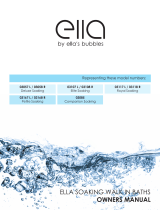
Step 1: Measure the length of the bottom of the orbital jigsaw. Add 1” to your measurement.
Step 2: Cut Velcro
®
according to your measurements.
A
B
Tip:
Velcro is recommended.
Step 3: Place the Velcro
®
on the bottom of the orbital jigsaw, leaving excess Velcro
®
hanging off each end.
Step 4: Wrap the excess Velcro
®
around both edges of the jigsaw. (Image A)
Step 5: Press rmly, and do the same to the other side. (Image B)
Step 6: Before cutting, make sure you are wearing your safety glasses and your orbital setting is on high.
Orbital Jigsaw Prep

www.ellasbubbles.com Page 7 08/14
Installation - Shower Bases

www.ellasbubbles.com Page 8 08/14
®
www.bciacrylic.com
22
Tip:
If you intend to use turnbuckle or crossbar drain on a at pan liner, you will need to install the adapter plate before you begin to install
the liner. If your pan liner has a dimpled recess, you can install the adapter plate after the liner is installed.
TURNBUCKLE DRAIN INSTALLATION
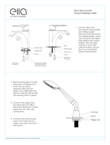
Step 1: Dremmel out the drain hole, be sure not to touch the acrylic. (Image J)
Step 2: Insert the turnbuckle into the pipe and tighten securely.
Step 3: Screw the adapter plate into the existing base with a at head screwdriver. (Image K)
Step 4: Screw the cover on top of the adapter with an allen wrench. (Image L)
J
K
L
CROSSBAR DRAIN INSTALATION
Step 5:
If you are installing this drain on a at liner, you will have already installed the crossbar under the liner. If installing on a liner with a dimpled recess,
place the crossbar on the recessed area. (Image M)
Step 6: Place the drain cap over drain hole.
Step 7: Secure in place with supplied screw using a athead screwdriver.
(Image N)
M
N
INSTALLATION / SHOWERLINERS & SHOWER BASES
INSTALLATION / SHOWERLINERS & SHOWER BASES
Shower Bases

www.ellasbubbles.com Page 9 08/14
®
www.bciacrylic.com
23
Step 1: Place the cover on the drain and trace the perimeter. Use a dremmel to cut out the hole, then remove the rag from the drain. (Image P)
Step 2: Snap the drain into place. (Image Q)
SNAPIN DRAIN INSTALLATION
P Q
O
INSTALLATION / SHOWERLINERS & SHOWER BASES
INSTALLATION / SHOWERLINERS & SHOWER BASES
Shower Bases

www.ellasbubbles.com Page 10 08/14
®
www.bciacrylic.com
30
TOOLS
o Pipe Wrench
o Hammer or Sledge
o Pry Bar
o Spud Wrench
o Sharpie® Marker
o Notepad
o Tape Measure
o Drop Cloths
o Utility Knife
Step 1: Remove all hardware, including the drain cover. (Image HH)
Step 2: Stuff a rag into the drain to keep debris from entering.
Step 3: Measure the drain center, from the soap dish wall to the center of the drain and again from the plumbing wall to the center of the drain. Record the
measurements.
(Image II)
Step 4: Use the small wall template to get the angles of the existing shower. Place the template in the corner of the existing base, with one end against the
soap dish wall and the other end against the plumbing wall. Set the template to t and tighten the lock knobs. (Image JJ)
INSTALLATION / SHOWERLINERS & SHOWER BASES
HH II JJ
Step 5: Carefully remove the template from the shower base. Do not bump the template. If you do, you will need to go back and re-template.
Step 6: Measure the height of the threshold by holding a straight edge out from the top of the rail, measure from the oor to the straight edge in 3 or 4
locations.
(Image KK)
Step 7: Add
3
/
8
” to your height measurements for thickness of acrylic material and adhesives. Record the measurements.
Step 8: Transfer measurements. To mark the drain center, place a straight edge in the drain area. Measure from the drain center to the soap dish wall and
mark your measurements. Then measure from the drain center to the plumbing wall and mark your measurement. (Image LL)
Step 9: Place the template along the marks, and trace the outside of the template. (Image MM)
KK LL
MM
INSTALLATION / SHOWERLINERS & SHOWER BASES
PAN LINER INSTALLATION
SHOWER PAN INSTALLATION
Shower Bases

www.ellasbubbles.com Page 11 08/14
®
www.bciacrylic.com
31
Step 10: Measure and mark the length of the liner, using the width line as a starting point. Use a straight edge to extend the line.
Step 11: Measure and mark the height of the threshold in 3 or 4 different locations. Connect the markings with a straight edge.
(Image NN)
Step 12: Using an orbital jigsaw, carefully cut the liner, supporting the liner with your other hand and keeping your ngers away from the blade.
Step 13: Test t the liner and trim as necessary. Now is the time to check the t to the existing pan and see if you will need additional layers of tape.
NN OO
PP
Step 14: Install the liner by placing butyl primer along the bottom of the acrylic liner, keeping away from the drain area and the rail of the threshold.
(Image OO) Then, prime the rail and the bottom of the existing base, again keeping away from the drain area. (Image PP)
Step 15: Place at tape on top of the primer, setting it paper to paper. Layer the tape as needed to ensure proper contact. Pull the release paper and
double-up tape along the perimeter. Remove the release paper.
(Image QQ)
Step 16: Place round tape along the shelf of the existing base 1/2” away from the wall. (Image RR) Remove the release paper. Place a continuous bead of
silicone around the perimeter between the round tape and the wall, and around the drain of the existing base.
(Image SS)
Step 17: Insert the pan liner, then walk up and down the perimeter to ensure proper contact. Wipe off any excess silicone.
Step 18: Install the new drain. Refer to page 22 for proper instructions.
Step 19: Once drain is installed, use silicone primer along the perimeter of the pan liner, followed by a color-matching silicone.
Tip:
If you intend to use a turn-buckle or crossbar drain on a at pan liner, you will need to install the adapter plate before you begin to install
the liner. If your pan liner has a dimpled recess, you can install the adapter plate after the liner is installed.
Tip:
It is okay if there is a tiny gap between the pan liner and existing walls. The walls can be built out to cover the gap.
QQ RR SS
INSTALLATION / SHOWERLINERS & SHOWER BASES
INSTALLATION / SHOWERLINERS & SHOWER BASES
PAN LINER INSTALLATION
CONTINUED
SHOWER LINER INSTALLATION (CONTINUED)
Shower Bases


www.ellasbubbles.com Page 13 08/14
Installation - Wall Surrounds

www.ellasbubbles.com Page 14 0 8/14
®
www.bciacrylic.com
37
INSTALLATION / WALL SURROUNDS
TOOLS
o Orbital Jigsaw with Bosch T101 Blade
or 10 to 12 Tooth-per-inch Wood Blade
o Level
o Screwdriver
o Suction Cup
o Large and Small Wall Templates
o Utility Knife
o Sharpie
®
Marker
o Notepad
o Tape Measure
o Hammer
o Chisel
o Pipe Wrench
o Handle Puller
o Work Table
o Extension Cords
o Vacuum
o Broom and Dust Pan
o Garbage Bags
o Drywall and Screws
o Pliers
o Tub Template
o Drop Cloths
SEQUENCE OF INSTALLATION:
Wall prep rst,then install the ceiling panel, then the soap dish wall. Next step is the two side walls
and then the bathliner.
Tip:
It is recommended to install the wall surrounds rst and then the bathliner. If you wish to install the bathliner rst, please refer to page 11
for proper instructions.
Tip:
If you need to replace the mixer valve, check the codes in the city where you are working. It is quite possible that a plumber may have
to do this work.
A B C
Step 1: Remove the hardware.
Step 2: Take off the plumbing xtures and accessories, which includes the faucet, showerhead, shower grab bars, soap dish and any other xtures. DO
NOT remove the overow cover. It will be removed later.
(Image A)
Step 3: If the existing tile does not go all the way to the ceiling, pad out the existing wall above the tile to ensure the wall is ush.
Tip:
Keep ¼” and ½” drywall sheets in your vehicle.
Step 4: To pad the wall, start by measuring the section of the wall that needs to be built-out. Transfer the measurements to the drywall, then cut the drywall
according to your measurements.
Step 5: Add silicone to the back of the drywall, then press it onto the existing wall. Screw the drywall onto the existing wall to keep it secure.
(Image B)
Tip:
Though drywall is the recommended way to repair a damaged wall, you may need to add additional layers of butyl tape to r out the wall
ush to the existing tile. Please note butyl tape is 1/8” thick, so you will need to assess the proper amount needed to ll the space. Layer the
tape one strip on top of another as needed. Pull the release paper as you layer, until you have the exact thickness.
Step 6: Clean the existing wall and tub system with industrial strength cleaner and denatured alcohol. Remove all of the old caulk around the perimeter of
the bathtub using a safety scraper.
(Image C)
WALL PREP
INSTALLATION / WALL SURROUNDS
Wall Surrounds

www.ellasbubbles.com Page 15 0 8/14
®
www.bciacrylic.com
38
INSTALLATION / WALL SURROUNDS
Step 1: Measure the depth from the soap dish wall to where the new ceiling panel will end in three separate locations. (Image D)
Step 2: Measure the width from the back wall to the plumbing wall in three separate locations. (Image E)
Step 3: Place the small wall template ush against the ceiling, with the long edge against the soap dish wall. This will measure the angles. (Image F)
Step 4: Adjust the template accordingly to nd the angles for both sides of the ceiling that touch the walls. Note any gaps due to bowed walls or other
miscellaneous reasons and adjust accordingly. Once you have the correct angle, tighten the lock-knobs and remove the template.
D E F
Tip:
Keep the clear or blue plastic slip sheeting on all the panels throughout the installation and make marks and cuts with it on. This will
help keep the panel from becoming scratched or damaged.
Step 5: Identify which end of your panel is the plumbing wall and which is the soap dish wall and mark accordingly. Transfer the depth marks on the panel,
measuring back from the bullnose edge to the soap dish wall side.
Tip:
In normal weather conditions, allow a 1/8” gap on all sides for standard expansion and contraction. This can be achieved by simply
cutting off your reference lines during the cutting process.
In extreme temperatures, the acrylic material may expand or contract up to ¼”. Allow around 20 minutes for the material to adjust to the climate
conditions inside the house.
Plumbing
Wall Side
Bullnose Edge
Soap Dish Wall Side
1
23
G
Plumbing
Wall Side
Bullnose Edge
Soap Dish Wall Side
H
Plumbing
Wall Side
Bullnose Edge
Soap Dish Wall Side
1
2
3
I
Tip:
The measurements will be reversed when they are transferred to the ceiling panel. The sheeted side where the markings are made will
actually be the new ceiling surface when installed. Be sure that you accurately identify which end of the panel is your plumbing wall and mark
it appropriately.
Step 6: Connect depth marks with a straight edge. Place the template on the panel. Use the template to trace the angle onto the acrylic ceiling panel.
Tip:
Be extremely careful not to bump the template once you have set your angles. If you do, you will need to go back and re-template.
Step 7: Hold the template up to your depth line and mark the plumbing wall angle. Remove the template and connect the marks using a straight edge.
Step 8: When measuring to get the width, use the plumbing wall template line as a starting point and create the opposite wall line. Double-check
your measurements.
CEILING PANEL INSTALLATION
INSTALLATION / WALL SURROUNDS
Wall Surrounds

www.ellasbubbles.com Page 16 08/14
®
www.bciacrylic.com
39
Step 9: Mark the bullnose edge using the bullnose line guide. The bullnose line guide is pre-marked with holes at 1/8” increments for ease of measuring.
Locate the appropriate measurement for your bullnose edge. For example, if you are cutting your bullnose edge at 1/4”, then locate the 1/4” hole.
Step 10: Place the Sharpie
®
marker into the appropriate hole and slide the bullnose line guide along the bullnose edge. (Image J)
J K L
Tip:
If there is no tile on the original ceiling, cut the bullnose edge at ¼”. This allows room for
1
/
8
” of acrylic or wall material and
1
/
8
” of tape
and adhesive.
Step 11: Cut the acrylic according to the measurements. Cut the panel slowly, carefully supporting the panel with your other hand and keeping your ngers
clear from the blade. Clean up your scraps as you go.
(Image K)
Tip:
Make sure your jigsaw is properly prepared. See page 9 for instructions.
Step 12: Wipe off panel with a terrycloth towel. Test t the panel, and mark any areas that may need to be trimmed.
Step 13: Trim any areas according to the new markings. Test t again. Continue trimming and re-test tting as needed.
Step 14: Once the ceiling ts, wipe down the existing ceiling with denatured alcohol.
Step 15: Make reference lines around the ceiling, about 1/2” inside the perimeter. Tap any excess primer off the brush and into the can so it does not drip,
then apply butyl primer around the perimeter and from side to side in lines approximately 5 to 9 inches apart.
(Image L)
Step 16: Make sure the primer is dry to the touch and apply the butyl tape on top of the primed areas. Press rmly when installing so the butyl tape does
not pull up when you remove the release paper.
Step 17: Remove the release paper. Apply the silicone in between the butyl tape in a “Z” pattern, keeping the bead about
¼” thick.
Step 18: Clean the back of the panel with denatured alcohol. To ensure proper adhesion throughout, press the ends of the panel near the plumbing and
back walls into place rst, then work your way towards the center. Make sure to apply even pressure throughout, and push up on the panel to adhere it to
the ceiling.
Step 19: Remove the slip sheeting and wipe down the panel to ensure it is pressed rmly into place.
INSTALLATION / WALL SURROUNDS
CEILING PANEL INSTALLATION CONTINUED
INSTALLATION / WALL SURROUNDS
Tip:
If primer spills, WD-40 can be used to remove it.
Tip:
If the tape is applied too close to an inside corner and comes in contact with the silicone, it may discolor the nished silicone due to the
carbon black in the butyl tape.
Tip:
Always use drop cloths to avoid spilling.
Tip:
Use suction cups to stabilize the panels when test tting and installing.
Wall Surrounds

www.ellasbubbles.com Page 17 08/14
®
www.bciacrylic.com
40
Step 1: Install corner reinforcements. Corner reinforcements are part of the triple gasketing system and are used to square up the walls and provide a more
permanent seal. Start by measuring from the top of the tub or shower base to the ceiling and record the measurement.
(Image M)
Step 2: Transfer the measurement to the reinforcement. Cut the reinforcement with tin snips. (Image N)
Step 3: Test t the corner reinforcement. Trim and re-test t as necessary.
Step 4: Once the reinforcement ts, clean and prep the existing walls using industrial strength cleaner and denatured alcohol.
Step 5: Apply silicone on both sides of the inside corners of the wall in a continuous bead from ceiling to top of tub or shower base. Press reinforcements
into place.
(Image O)
M N O
Step 1: Using the large wall template, place the long edge against the plumbing wall and the short sides against the ceiling and top of tub or shower base.
(Image P)
Step 2: Check for any gaps due to bowed walls or any other miscellaneous reasons and adjust accordingly.
Step 3: Tighten the large lock-knobs securely.
(Image Q)
Step 4: Use the template to transfer the measurements onto the soap dish wall panel. Place the template onto the new wall panel, ush with the top ceiling
edge, and make three marks along all three sides of the template.
(Image R)
Tip:
Another continuous bead of silicone will be added on top of the corner reinforcements before nal wall installation and after walls are
in place.
P Q R
There are two measuring options: the template method and the level method. The following is the template method. Please refer to
page 37 for level method.
Tip:
Be extremely careful not to bump the template once you have set your angles. If you do, you will need to go back and re-template.
INSTALLATION / WALL SURROUNDS
SOAP DISH WALL INSTALLATION
SOAP DISH WALL — TEMPLATE MEASURE OPTION
INSTALLATION / WALL SURROUNDS
®
www.bciacrylic.com
41
2
1
/
4
2
1
/
4
2
1
/
4
72
1
/
2
72
1
/
2
72
1
Step 5: Connect markings with a straight edge.
Step 6: Measure from the plumbing wall to back wall and record the measurements. (Image S) Transfer these measurements by making three width marks
on the panel, using the plumbing wall line as the starting point.
Step 7: Connect the lines with a straight edge. (Image T) This will be the back wall.
S
Plumbing Wall Side
T
When your project includes simulated tile walls, you will need to take some additional time to pre-plan before cutting to ensure your
grout lines will match up on all three panels. This can be done by taking accurate measurements of your soap dish wall and preliminary
measurements of your plumbing and back walls. You always want to be sure the full tile is at the top, and equal spacing of tiles are on the left
and right.
Step 1: Draw a level horizontal line across the soap dish wall, from plumbing wall to back wall. Measure from the horizontal line up to the ceiling in three
different locations to determine if the ceiling is level. Record the measurements on the existing wall. (Image U)
There are two measuring options: the template method and the level method. The following is the level method. Please refer to page 36
for template method.
Note:
If your ceiling is not level, cut the top edge of the wall panel according to the difference in your measurements.
Step 2: Measure from the top of the shower base or tub up to the horizontal line in three different locations. Add these measurements to the measure-
ments you took from the level line to the ceiling, and record them on the existing wall. (Image V)
Step 3: Draw a vertical plumb line from the top of the shower base or tub to the ceiling. Measure from the vertical line to the plumbing wall corner reinforce-
ments at 3 or 4 different locations to determine if the wall is plumb. Record the measurements on the existing wall. (Image W)
U
2
2
2
72
/
72
/
72
V W
INSTALLATION / WALL SURROUNDS
SOAP DISH WALL INSTALLATION
CONTINUED
SOAP DISH WALL — LEVEL MEASURE OPTION
INSTALLATION / WALL SURROUNDS
Wall Surrounds

www.ellasbubbles.com Page 18 08/14
®
www.bciacrylic.com
41
2
1
/
4
2
1
/
4
2
1
/
4
72
1
/
2
72
1
/
2
72
1
Step 5: Connect markings with a straight edge.
Step 6: Measure from the plumbing wall to back wall and record the measurements. (Image S) Transfer these measurements by making three width marks
on the panel, using the plumbing wall line as the starting point.
Step 7: Connect the lines with a straight edge. (Image T) This will be the back wall.
S
Plumbing Wall Side
T
When your project includes simulated tile walls, you will need to take some additional time to pre-plan before cutting to ensure your
grout lines will match up on all three panels. This can be done by taking accurate measurements of your soap dish wall and preliminary
measurements of your plumbing and back walls. You always want to be sure the full tile is at the top, and equal spacing of tiles are on the left
and right.
Step 1: Draw a level horizontal line across the soap dish wall, from plumbing wall to back wall. Measure from the horizontal line up to the ceiling in three
different locations to determine if the ceiling is level. Record the measurements on the existing wall. (Image U)
There are two measuring options: the template method and the level method. The following is the level method. Please refer to page 36
for template method.
Note:
If your ceiling is not level, cut the top edge of the wall panel according to the difference in your measurements.
Step 2: Measure from the top of the shower base or tub up to the horizontal line in three different locations. Add these measurements to the measure-
ments you took from the level line to the ceiling, and record them on the existing wall. (Image V)
Step 3: Draw a vertical plumb line from the top of the shower base or tub to the ceiling. Measure from the vertical line to the plumbing wall corner reinforce-
ments at 3 or 4 different locations to determine if the wall is plumb. Record the measurements on the existing wall. (Image W)
U
2
2
2
72
/
72
/
72
V W
INSTALLATION / WALL SURROUNDS
SOAP DISH WALL INSTALLATION CONTINUED
SOAP DISH WALL — LEVEL MEASURE OPTION
INSTALLATION / WALL SURROUNDS
Wall Surrounds

www.ellasbubbles.com Page 19 0 8/14
®
www.bciacrylic.com
42
INSTALLATION / WALL SURROUNDS
Tip:
Try to measure the walls using the same increments on both sides.
Step 4: Measure from the plumbing wall to the back wall in the same 3 or 4 different locations you used to check if the wall was plumb. (Image X)
SOAP DISH WALL INSTALLATION CONTINUED
Step 5: Write all of your measurements on your notepad. Transfer your measurements to your new wall panel and, using a straight edge, draw lines con-
necting the marks. (Image Y)
Tip:
When your project includes simulated tile walls, you will need to take some additional time to pre-plan before cutting to ensure
your grout lines will match up on all three panels. This can be done by taking accurate measurements of your soap dish wall and preliminary
measurements of your plumbing and back walls. You always want to be sure the full tile is at the top, and equal spacing of tiles are on the left
and right.
2
2
2
72
/
72
/
72
1
/
4
2
2
2
52
/
X Y
Step 6: Cut the wall panel slowly, carefully support the panel with your other hand and keeping your ngers clear from the blade. Clean up scraps as you
go. (Image Z)
Step 7: Test t the panel and mark necessary adjustments. (Image AA) Use suction cups to assist in handling the panel during the test t and installation.
Tip:
Be real careful with larger panels while walking through the customers’ home.
Step 8: Continue to measure, trim and test t until you have a desired t.
Step 9: Wipe down the existing wall with denatured alcohol. Tap any excess primer off your brush and into the can so it does not drip, then apply it around
the perimeter, staying ½” away from the edge, and from side to side in lines approximately 5 to 9 inches apart.
Tip:
If using simulated tile, the suction cups will not adhere to the panel. Instead, you can pull down a section of the plastic slip sheeting to
create handles and use those to help put the wall in place. (Image BB)
Z AA BB
SOAP DISH WALL INSTALLATION CONTINUED
SOAP DISH WALL — LEVEL MEASURE OPTION CONTINUED
INSTALLATION / WALL SURROUNDS
Wall Surrounds

www.ellasbubbles.com Page 20 0 8/14
®
www.bciacrylic.com
43
INSTALLATION / WALL SURROUNDS
Step 10: Make sure the primer is dry to the touch and apply the butyl tape on top of the primed areas. Press rmly when installing so the butyl tape does
not pull up when you remove the release paper.
(Image CC)
Step 11: Remove the release paper. Apply the silicone in between the butyl tape in a “Z” pattern, keeping the bead about ¼” thick. (Image DD)
Step 12: Clean the back of the new panel with denatured alcohol or damp cloth. Press the panel rmly into place. (Image EE) Remove the slip sheeting and
wipe down the panel to ensure it is secured.
CC DD EE
BULLNOSE EDGE FINISHES
There are three options for nishing the ends of your side walls—Option 1: the bullnose edge; Option 2: the use of a tri-guard
under the wall panel; or Option 3: the use of a tri-guard over the wall panel.
SOAP DISH WALL INSTALLATION CONTINUED
PLUMBING WALL INSTALLATION
Tip:
If you notice extensive damage to the corner bead, mud and sand the wall.
OPTION 1 - Bullnose Edge (Image FF)
Step 1: If the tile extends to the end of the wall, you will need to remove the last row of tile. Place a drop cloth over the oor and existing tub or shower base.
Step 2: Score along the edge of the tile to prevent damage to the existing wall and remaining tiles.
(Image GG)
Step 3: Break out the rst row of tile with a hammer and small pry bar. (Image HH)
Side Wall Panal
Bathroom Wall
FF GG HH
Step 4: The bullnose edge will be cut during the cutting step of plumbing wall installation.
INSTALLATION / WALL SURROUNDS
Add the existing tile thickness measure to the ¼”, previously mentioned, that allows for an 1/8” of acrylic or wall material and 1/8”
of tape and adhesive. (If the tile is 3/8” thick, the bullnose edge would be cut at 5/8”.)
Wall Surrounds
/